EP1468203B1 - Agencement de refroidissement pour etrier de frein - Google Patents
Agencement de refroidissement pour etrier de frein Download PDFInfo
- Publication number
- EP1468203B1 EP1468203B1 EP02715493A EP02715493A EP1468203B1 EP 1468203 B1 EP1468203 B1 EP 1468203B1 EP 02715493 A EP02715493 A EP 02715493A EP 02715493 A EP02715493 A EP 02715493A EP 1468203 B1 EP1468203 B1 EP 1468203B1
- Authority
- EP
- European Patent Office
- Prior art keywords
- piston
- pad
- brake
- cooling medium
- caliper
- Prior art date
- Legal status (The legal status is an assumption and is not a legal conclusion. Google has not performed a legal analysis and makes no representation as to the accuracy of the status listed.)
- Expired - Lifetime
Links
Images



Classifications
-
- F—MECHANICAL ENGINEERING; LIGHTING; HEATING; WEAPONS; BLASTING
- F16—ENGINEERING ELEMENTS AND UNITS; GENERAL MEASURES FOR PRODUCING AND MAINTAINING EFFECTIVE FUNCTIONING OF MACHINES OR INSTALLATIONS; THERMAL INSULATION IN GENERAL
- F16D—COUPLINGS FOR TRANSMITTING ROTATION; CLUTCHES; BRAKES
- F16D65/00—Parts or details
- F16D65/78—Features relating to cooling
- F16D65/84—Features relating to cooling for disc brakes
- F16D65/847—Features relating to cooling for disc brakes with open cooling system, e.g. cooled by air
-
- F—MECHANICAL ENGINEERING; LIGHTING; HEATING; WEAPONS; BLASTING
- F16—ENGINEERING ELEMENTS AND UNITS; GENERAL MEASURES FOR PRODUCING AND MAINTAINING EFFECTIVE FUNCTIONING OF MACHINES OR INSTALLATIONS; THERMAL INSULATION IN GENERAL
- F16D—COUPLINGS FOR TRANSMITTING ROTATION; CLUTCHES; BRAKES
- F16D55/00—Brakes with substantially-radial braking surfaces pressed together in axial direction, e.g. disc brakes
- F16D55/02—Brakes with substantially-radial braking surfaces pressed together in axial direction, e.g. disc brakes with axially-movable discs or pads pressed against axially-located rotating members
- F16D55/22—Brakes with substantially-radial braking surfaces pressed together in axial direction, e.g. disc brakes with axially-movable discs or pads pressed against axially-located rotating members by clamping an axially-located rotating disc between movable braking members, e.g. movable brake discs or brake pads
- F16D55/224—Brakes with substantially-radial braking surfaces pressed together in axial direction, e.g. disc brakes with axially-movable discs or pads pressed against axially-located rotating members by clamping an axially-located rotating disc between movable braking members, e.g. movable brake discs or brake pads with a common actuating member for the braking members
-
- F—MECHANICAL ENGINEERING; LIGHTING; HEATING; WEAPONS; BLASTING
- F16—ENGINEERING ELEMENTS AND UNITS; GENERAL MEASURES FOR PRODUCING AND MAINTAINING EFFECTIVE FUNCTIONING OF MACHINES OR INSTALLATIONS; THERMAL INSULATION IN GENERAL
- F16D—COUPLINGS FOR TRANSMITTING ROTATION; CLUTCHES; BRAKES
- F16D65/00—Parts or details
- F16D65/14—Actuating mechanisms for brakes; Means for initiating operation at a predetermined position
- F16D65/16—Actuating mechanisms for brakes; Means for initiating operation at a predetermined position arranged in or on the brake
- F16D65/18—Actuating mechanisms for brakes; Means for initiating operation at a predetermined position arranged in or on the brake adapted for drawing members together, e.g. for disc brakes
-
- F—MECHANICAL ENGINEERING; LIGHTING; HEATING; WEAPONS; BLASTING
- F16—ENGINEERING ELEMENTS AND UNITS; GENERAL MEASURES FOR PRODUCING AND MAINTAINING EFFECTIVE FUNCTIONING OF MACHINES OR INSTALLATIONS; THERMAL INSULATION IN GENERAL
- F16D—COUPLINGS FOR TRANSMITTING ROTATION; CLUTCHES; BRAKES
- F16D55/00—Brakes with substantially-radial braking surfaces pressed together in axial direction, e.g. disc brakes
- F16D2055/0004—Parts or details of disc brakes
- F16D2055/0016—Brake calipers
- F16D2055/002—Brake calipers assembled from a plurality of parts
-
- F—MECHANICAL ENGINEERING; LIGHTING; HEATING; WEAPONS; BLASTING
- F16—ENGINEERING ELEMENTS AND UNITS; GENERAL MEASURES FOR PRODUCING AND MAINTAINING EFFECTIVE FUNCTIONING OF MACHINES OR INSTALLATIONS; THERMAL INSULATION IN GENERAL
- F16D—COUPLINGS FOR TRANSMITTING ROTATION; CLUTCHES; BRAKES
- F16D65/00—Parts or details
- F16D65/78—Features relating to cooling
- F16D2065/783—Features relating to cooling cooling control or adjustment
-
- F—MECHANICAL ENGINEERING; LIGHTING; HEATING; WEAPONS; BLASTING
- F16—ENGINEERING ELEMENTS AND UNITS; GENERAL MEASURES FOR PRODUCING AND MAINTAINING EFFECTIVE FUNCTIONING OF MACHINES OR INSTALLATIONS; THERMAL INSULATION IN GENERAL
- F16D—COUPLINGS FOR TRANSMITTING ROTATION; CLUTCHES; BRAKES
- F16D2121/00—Type of actuator operation force
- F16D2121/02—Fluid pressure
-
- F—MECHANICAL ENGINEERING; LIGHTING; HEATING; WEAPONS; BLASTING
- F16—ENGINEERING ELEMENTS AND UNITS; GENERAL MEASURES FOR PRODUCING AND MAINTAINING EFFECTIVE FUNCTIONING OF MACHINES OR INSTALLATIONS; THERMAL INSULATION IN GENERAL
- F16D—COUPLINGS FOR TRANSMITTING ROTATION; CLUTCHES; BRAKES
- F16D2125/00—Components of actuators
- F16D2125/02—Fluid-pressure mechanisms
- F16D2125/04—Cylinders
-
- F—MECHANICAL ENGINEERING; LIGHTING; HEATING; WEAPONS; BLASTING
- F16—ENGINEERING ELEMENTS AND UNITS; GENERAL MEASURES FOR PRODUCING AND MAINTAINING EFFECTIVE FUNCTIONING OF MACHINES OR INSTALLATIONS; THERMAL INSULATION IN GENERAL
- F16D—COUPLINGS FOR TRANSMITTING ROTATION; CLUTCHES; BRAKES
- F16D2125/00—Components of actuators
- F16D2125/02—Fluid-pressure mechanisms
- F16D2125/06—Pistons
Definitions
- the invention relates to a brake caliper with at least one axially displaceable, hydraulically actuated piston, with which at least one brake pad can be pressed against a brake disc, a piston for use with such a caliper and a brake pad for use with such a caliper.
- friction linings or "brake pads” are, during the braking operation, pressed axially against the brake disc rotating with the wheel of a vehicle.
- the resultant friction converts rotational energy into heat.
- the heat generated causes an increase in the temperature of the brake disc, the brake pads and the brake caliper.
- Thermal conduction and thermal radiation also heat the piston, the hydraulic fluid, the space accommodating the hydraulic fluid and the seals that isolate the hydraulic fluid from the environment.
- the combination of brake disc and pad is cooled in order to dissipate the heat generated by a braking operation.
- the temperature gradient between the heated components and the environment is sufficient for heat dissipation. Greater cooling can be achieved if the heated components are exposed to an air current. Internally ventilated disc brakes are one example of this.
- This cooling primarily removes heat from the brake disc and the pads. This heat dissipation leads to lower pad temperatures, which also results in lower temperatures of the piston, in the hydraulic fluid and in the seals.
- the brake fluid must also not be exposed to excessively high temperatures. If, as a result of excessive heat input, the temperature of the brake fluid rises beyond its boiling point, bubbles are formed as a result of boiling. Under these circumstances, it is no longer possible to build up a controlled pressure in the brake fluid. The brake can no longer be operated reliably.
- the brake disc is directly cooled by a flow of air.
- openings in the end face of a hollow piston body allow cooling air to circulate.
- apertures in the pad end of the piston allow air circulation.
- the objection of the invention is thus to create a device with which the temperature can be kept low, especially in the region of the piston of a disc brake.
- a brake caliper as set out in claim 1.
- the piston can be cooled by the cooling medium entering the cavity of the piston through the inlet opening.
- the cooled piston surfaces also cool the seals and the hydraulic fluid. This makes it possible to influence the temperature of the piston, the brake fluid and the seals, as well as of other components in the direct vicinity of the piston. As a result, the temperature of the hydraulic fluid can be kept within a normal range, even at very high brake powers.
- the cooling medium used is preferably air or another suitable cooling medium.
- the flow of the medium through the piston can be influenced by setting a pressure upstream of the inlet opening.
- This invention results in a main direction of cooling medium flow through the piston that is directed at the pad or pads.
- the pad is also cooled by the cooling medium flowing against it.
- heat is also removed from the pad by the thermal conduction between the friction lining and the cooled piston.
- Suitable devices such as deflectors within the piston cavity, can be used to influence the cooling medium flow.
- the cooling medium can be directed to the points of the piston requiring particular cooling.
- the areas of the piston that run over the seals can be mentioned as an example in this context.
- the piston walls that are in direct contact with the hydraulic fluid to be cooled can also be cooled in this way.
- the piston preferably comprises two hollow, coaxial cylinders of different diameters.
- the pad pressed against the brake disc by the piston is located on a face end of the cylinder with the larger diameter.
- the face end of the cylinder with the larger diameter that faces away from the pad can lie in the plane of the face end of the cylinder with the smaller diameter that faces the pad.
- the piston wall extends in the plane perpendicular to the cylinder axis only from the lateral surface of the cylinder with the larger circumference to the lateral surface of the cylinder with the small diameter.
- the annular piston wall between the lateral surfaces of the cylinders is pressurised so that the piston can be pressed against the brake disc along with the pad.
- An opening, through which the cooling medium enters the piston cavity, can be provided on the face end of the cylinder with the smaller diameter that faces away from the pad. In this case, the cooling medium then flows through the cylinder with the small diameter into the cylinder with the larger diameter.
- the piston can comprise one cylinder, where the pad is located on one face end of the cylinder.
- a circular opening can be provided in the other face end of the cylinder, the centre of the circle of which is located on the axis of the cylinder.
- a flow-through device can extend through this opening.
- the cooling medium can enter the piston cavity through this flow-through device, which can be designed as a section of pipe.
- the openings can be arranged around the circumference of the cylinder at regular intervals.
- a brake according to claim 15 the brake pad having a surface against which a piston of a caliper can be arranged to press, the surface having a cooling medium passageway formed therein arranged to receive cooling medium from the piston and to direct the medium array from the piston through the pad to cool the pad.
- Piston 1 shown in Fig. 1 comprises two hollow cylinders 2 and 4, the lateral surfaces of which are connected by annular piston wall 3. Interior space 7, which accommodates the hydraulic fluid and into which the hydraulic fluid passes through opening 6, is sealed off from the environment by annular seals 5a and 5b.
- Piston 1 with pad 8 is pressed against brake disc 9 by building up pressure in interior space 7.
- the frictional forces between pad 8 and brake disc 9 decelerate brake disc 9, which rotates about axis of rotation 10.
- inlet opening 12 Provided in the face end of cylinder 4 with the smaller diameter that faces away from the pad is inlet opening 12, which extends over the entire face end.
- the cooling medium flows through inlet opening 12 into the cavity of piston 1.
- Several slit-type outlet openings 11 are provided on the face end of the cylinder 2 with the larger diameter, on which pad 8 is located.
- the cooling medium preferably air, flows out of the cavity of piston 1 through these outlet openings 11.
- the air flowing out of the cavity through the outlet openings 11 impinges on the brake disc 9 to provide further cooling.
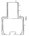
- the piston 1 in Fig.2 is substantially the same as that shown in Fig.1 and parts corresponding to parts in Fig.1 carry the same reference numerals.
- the outlet opening 11 at the pad end of the piston 1 is wider than the slit-like openings of Fig.1 .
- two such openings are provided.
- One, three or more openings may be provided in the alternative.
- the piston 1 does not have the openings 11 but is open at both ends thereof. In that case the piston 1 abuts the brake pad 8 shown in Figs.6 and 7 described in more detail below.
- FIG 3 shows a longitudinal section of another practical example according to the invention.
- the hydraulic fluid enters interior space 7, which accommodates the hydraulic fluid, through opening 6.
- Piston 1 is of cylindrical shape, where pad 8 is located on one face end.
- annular seal 5b Provided between the section of pipe and the inlet opening is an annular seal 5b, which separates the piston cavity from interior space 7, in which the brake fluid is located.
- Several slit-type outlet openings 11 are provided on the edge of the face end on which pad 8 is located.
- an annular seal 5a is located between the peripheral surface of the cylinder forming the piston and the wall of interior space 7.
- the openings 11 may be formed by drilling holes through the wall of the piston adjacent the pad 8.
- caliper illustrated in Fig.4 is similar to that in Fig.3 and parts corresponding to parts in Fig.3 carry the same reference numerals.
- the piston 1 in Fig.4 is cylindrical and a chimney-like flow through device 13 extends from the wall of the caliper into the interior space of the piston 1.
- the piston 1 is formed in two pieces 1a, 1b.
- the first piston piece 1a is a hollow cylinder with an annular channel 14 formed on the inner surface thereof.
- the channel 14 is arranged to receive the annular seal 5b which seals against the outer surface of the flow through device 13.
- the annular channel 14 protrudes slightly from the inner wall of the hollow piston 1 and is arranged slightly in from one end of the piston so as to define an interior space 7 into which hydraulic fluid can enter from the brake fluid reservoir (not shown).
- the piston 1 is slidable in a bore 15 and the outer wall of the piston 1 is sealed against the bore 15 by means of an annular seal 5a formed in an annular channel 16 in the bore 15 adjacent the mouth thereof.
- the second piston piece 16 comprises an end cap which is secured to the first piston piece 1a at the end spaced from the inner annular channel 14 by means of a ring (not shown) in co-operating annular grooves 17a, b around the end cap 1b and on the inner surface of the first piston piece 1a.
- the end cap 1b is fixed to the first piston piece 1a so that they move together as a unit.
- the end cap 16 is provided as an additional thermal barrier.
- the end cap 1b comprises a cylindrical portion 18 which extends into the hollow interior of the first piston piece 1a from the end thereof spaced from the annular channel 14.
- the end cap 1b further comprises an annular shoulder portion 19 which extends outwardly of the cylindrical portion 18 and against which the end of the first piston piece 1a abuts.
- Extending from the periphery of the shoulder portion 18 in the axial direction of the piston 1 is a plurality of regularly spaced crenellations 20 which define spaces therebetween.
- the spaces between the crenellations constitute the aforesaid outlet openings 11.
- the profile shown in broken lines in Fig.4 represents the extent of maximum piston travel.
- the tips of the crenellations, in use, abut the rear surface of a brake pad 8 (not shown).
- the hydraulic brake fluid is supplied under pressure to the space 7 which serves to push the piston 1 axially out of the bore 15, pushing the pad 8 against the brake disc 9 (not shown).
- Air is supplied under pressure through the flow through device 13, which serves to cool the interior of piston 1. The air flows through the piston 1, strikes the rear surface of the pad 8 (not shown) and escapes from the piston 1 through the openings 11 between the crenellations 20.
- the outlet openings 11 in the side wall of the piston 1 or between the crenellations 20 respectively can be omitted.
- the air outlet from the piston preferably comprises the open end of the piston 1.
- the end face of the piston 1 which abuts the rear surface of the brake pad 8 is preferably smooth so as to abut the pad flush against the rear surface thereof.
- the pad 8 is as shown in Figs. 6 and 7 .
- the pad 8 shown in Figs. 6 and 7 is shown rectangular in shape for simplicity but any pad shape is envisaged.
- the pad 8 has front surface 8a which is arranged to be pressed against the brake disc 9, in use.
- the pad 8 further includes a rear surface 8b against which the piston 1 abuts.
- a blind bore 21 is formed in the pad so as to lie generally centrally of the piston axis, extending from the rear surface 8b, perpendicular thereto, part of the way into the pad 8 (see Fig.7 ).
- Coolant flow passageways 22 are formed extending radially outwardly from the bore 21 in fluid communication therewith. Each passageway 22 extends from the bore 21 to the peripheral edge of the pad 8. In the embodiment illustrated, four coolant flow passageways 22 are provided at regular angular intervals. Alternatively radial grooves may be formed in the rear surface by machining.
- the piston 1 abuts the rear surface 8b of the pad 8 and presses the front surface 8a against the disc 9 which generates frictional heat.
- the coolant air flows through the piston 1 as described above in relation to Figs.2 and 4 . However, instead of escaping through outlet openings 11 in the piston 1, the air passes into the bore 21 and through the passageways 22 to atmosphere, thus cooling the pad 8 in addition to the piston 1.
- the coolant flow through the piston is regulated by controlling the pressure of the coolant upstream of the piston 1.
- the coolant is air
- a compressor (not shown) may be provided to pump air through the piston at variable pressures.
- ambient air may be drawn from atmosphere and directed through the piston, for example by means of an air scoop which scoops ambient air as the vehicle travels through it and ducting to duct the air to the brake caliper.
- a regulator valve may be provided upstream of the caliper to regulate incoming air pressure or the scoop aperture may be varied in size depending upon cooling requirements.
Landscapes
- Engineering & Computer Science (AREA)
- General Engineering & Computer Science (AREA)
- Mechanical Engineering (AREA)
- Braking Arrangements (AREA)
Claims (18)
- Etrier de frein ayant une paroi d'étrier définissant un cylindre (7) avec au moins un piston déplaçable axialement et actionné hydrauliquement (1) reçu dans le cylindre, avec lequel une plaquette de frein (8) peut être pressée contre un disque de frein (9), le piston définissant une cavité à l'intérieur de celui-ci, avec au moins une ouverture d'entrée (12) pour alimenter un support de refroidissement dans la cavité, l'ouverture d'entrée étant agencée dans le piston espacé de la plaquette de frein, et au moins une ouverture de sortie (11) agencée dans le piston adjacent à la plaquette de frein pour évacuer le support de refroidissement de la cavité, caractérisé en ce qu'un dispositif traversant le flux (13) s'étend de la paroi d'étrier dans l'espace intérieur du piston (1) pour permettre le passage d'un support de refroidissement de l'extérieur de la paroi d'étrier dans la cavité.
- Etrier de frein selon la revendication 1,
caractérisé en ce que le dispositif traversant le flux (13) fait partie intégrante de la paroi de l'étrier de frein. - Etrier de frein selon la revendication 1 ou 2,
caractérisé en ce que le piston (1) comprend un cylindre creux, dans lequel le revêtement de frottement (8) est situé sur une extrémité de face du cylindre et une ouverture d'entrée coaxiale (12), à travers laquelle le dispositif traversant le flux (13) s'étend, est fournie dans l'autre extrémité de face. - Etrier de frein selon la revendication 2 ou 3,
caractérisé en ce que le piston est formé de deux parties (1a, 1b). - Etrier de frein selon la revendication 4,
caractérisé en ce qu'une première partie de piston (1a) est un cylindre creux avec un canal annulaire (14) formé sur la surface intérieure de celui-ci. - Etrier de frein selon la revendication 5, caractérisé en ce que le canal annulaire (14) est agencé pour recevoir un joint annulaire (5b) qui se scelle contre la surface extérieure du dispositif traversant le flux (13).
- Etrier de frein selon la revendication 5 ou 6,
caractérisé en ce que la deuxième partie de piston (1b) comprend un capuchon d'extrémité qui est fixé à la première partie de piston (1a) à l'extrémité espacée du canal annulaire intérieur (14) au moyen d'un anneau dans des gorges annulaires en coopération (17a, 17b) autour du capuchon d'extrémité et sur la surface intérieure de la première partie de piston (1a). - Etrier de frein selon l'une des revendications 1 à 7, caractérisé en ce que les ouvertures de sortie (11) sont situées à des intervalles réguliers au bord de l'extrémité de surface du cylindre sur lequel le revêtement de frottement (8) est situé, ou les ouvertures (11) sont percées à travers la paroi du piston adjacent à la plaquette.
- Etrier de frein selon l'une des revendications 1 à 8,
caractérisé en ce que des dispositifs pour influencer le flux de support de refroidissement sont fournis dans la cavité du piston (1). - Etrier de frein selon l'une des revendications 1 à 9, caractérisé en ce que l'étrier de frein comprend une plaquette de frein ayant une surface (86) contre laquelle un piston d'un étrier peut être agencé pour presser, la surface ayant un passage de support de refroidissement (22) formé à l'intérieur de celle-ci agencé pour recevoir le support de refroidissement du piston et pour conduire le support à l'écart du piston.
- Etrier de frein selon la revendication 10,
caractérisé en ce qu'un alésage aveugle (21) est formé dans la plaquette de manière à se trouver généralement centralement dans l'axe du piston, s'étendant de la surface arrière (8b), perpendiculairement à celle-ci, sur une partie du chemin dans la plaquette (8). - Etrier de frein selon la revendication 11, caractérisé en ce que les passages de flux de refroidissement sont formés en s'étendant radialement vers l'extérieur à partir de l'alésage (21) en communication fluide avec celui-ci.
- Piston d'étrier de frein (1) destiné à être utilisé dans un étrier de frein pour presser une plaquette de frein (8) contre un disque de frein, le piston (1) définissant une cavité et ayant une première extrémité, une ouverture d'entrée (11) pour alimenter un support de refroidissement dans la cavité dans la première extrémité ou adjacente à celle-ci et une deuxième extrémité agencée pour presser contre une plaquette de frein et une ouverture de sortie (11) dans la deuxième extrémité ou adjacente à celle-ci, la première extrémité étant espacée de la deuxième extrémité, caractérisé en ce que le piston (1) comprend deux cylindres creux coaxiaux (2, 4) de diamètres différents, l'un des cylindres s'étendant à travers la paroi d'étrier pour servir de passage au support de refroidissement de l'extérieur de la paroi d'étrier dans la cavité.
- Piston d'étrier de frein selon la revendication 13, dans lequel une pluralité d'ouvertures de sortie sont fournies, chaque ouverture étant agencée dans la deuxième extrémité ou adjacente à celle-ci.
- Plaquette de frein (8) destinée à être utilisée dans un étrier de frein, la plaquette de frein (8) ayant une surface (8b) contre laquelle un piston d'un étrier peut être agencé pour presser, la surface ayant un passage de support de refroidissement (22) formé à l'intérieur de celle-ci agencé pour recevoir un support de refroidissement du piston et pour conduire le support à l'écart du piston à travers la plaquette pour refroidir la plaquette.
- Plaquette de frein selon la revendication 15, dans laquelle le passage de support de refroidissement comprend un alésage aveugle (21) s'étendant de la surface de plaquette (8b) dans la plaquette.
- Plaquette de frein selon la revendication 15 ou 16,
dans laquelle le passage de support de refroidissement comprend un passage de liquide de refroidissement radial (21) s'étendant du centre de la plaquette au bord périphérique de celle-ci. - Plaquette de frein selon la revendication 15, dans laquelle le passage de support de refroidissement comprend un alésage aveugle (21) s'étendant de la surface de plaquette (8b) dans la plaquette et une pluralité de passages de liquide de refroidissement radiaux (22) s'étendant de l'alésage aveugle au bord périphérique de la plaquette.
Applications Claiming Priority (1)
| Application Number | Priority Date | Filing Date | Title |
|---|---|---|---|
| PCT/GB2002/000140 WO2003058088A1 (fr) | 2002-01-14 | 2002-01-14 | Agencement de refroidissement pour etrier de frein |
Publications (3)
| Publication Number | Publication Date |
|---|---|
| EP1468203A1 EP1468203A1 (fr) | 2004-10-20 |
| EP1468203B1 true EP1468203B1 (fr) | 2008-09-24 |
| EP1468203B2 EP1468203B2 (fr) | 2011-10-12 |
Family
ID=9928624
Family Applications (1)
| Application Number | Title | Priority Date | Filing Date |
|---|---|---|---|
| EP02715493A Expired - Lifetime EP1468203B2 (fr) | 2002-01-14 | 2002-01-14 | Agencement de refroidissement pour etrier de frein |
Country Status (7)
| Country | Link |
|---|---|
| US (1) | US7353919B2 (fr) |
| EP (1) | EP1468203B2 (fr) |
| JP (1) | JP4278519B2 (fr) |
| AT (1) | ATE409292T1 (fr) |
| AU (1) | AU2002225142B2 (fr) |
| DE (1) | DE60229071D1 (fr) |
| WO (1) | WO2003058088A1 (fr) |
Families Citing this family (21)
| Publication number | Priority date | Publication date | Assignee | Title |
|---|---|---|---|---|
| WO2002099305A1 (fr) * | 2001-06-04 | 2002-12-12 | Freni Brembo S.P.A. | Piston de frein |
| DE602004023136D1 (de) * | 2004-09-29 | 2009-10-22 | Freni Brembo Spa | Scheibenbremsensattel mit einem kühlkanal |
| WO2007076535A1 (fr) * | 2005-12-29 | 2007-07-05 | Hb Performance Systems, Inc. | Etrier a transfert thermique eleve |
| WO2008047840A1 (fr) * | 2006-10-19 | 2008-04-24 | Nukabe Corporation | Étrier de frein pour frein à disque |
| US8291868B2 (en) * | 2008-12-09 | 2012-10-23 | Whallon Lester P | Brake furnace |
| CN107420467A (zh) | 2011-01-14 | 2017-12-01 | 喜达迪有限公司 | 制动活塞和活塞鼻部 |
| US9267557B2 (en) * | 2011-12-13 | 2016-02-23 | Akebono Brake Corporation | Heat transfer preventer |
| GB2515063A (en) * | 2012-03-02 | 2014-12-17 | Trevor Michael Mennie | Brake system |
| WO2014199129A1 (fr) * | 2013-06-12 | 2014-12-18 | Mennie Trevor Michael | Ensemble plaquette de frein |
| RU2546391C2 (ru) * | 2013-08-23 | 2015-04-10 | Федеральное государственное бюджетное образовательное учреждение высшего профессионального образования "Омский государственный технический университет" | Поршневой компрессор без смазки |
| US9573571B2 (en) * | 2014-10-31 | 2017-02-21 | GM Global Technology Operations LLC | Venturi brake duct assembly |
| GB2536926B (en) | 2015-03-31 | 2021-04-21 | Alcon Components Ltd | Brake disc |
| CN105276042A (zh) * | 2015-11-29 | 2016-01-27 | 重庆元创汽车整线集成有限公司 | 带冷却系统的浮钳盘式制动器 |
| CN107975549B (zh) * | 2017-11-28 | 2019-06-07 | 安徽科源机械有限公司 | 一种汽车制动器 |
| CN107989936B (zh) * | 2017-11-28 | 2019-06-21 | 安徽科源机械有限公司 | 一种具有散热功能的汽车制动器 |
| DE102018218195B4 (de) * | 2018-10-24 | 2021-08-26 | Mando Corporation | Hydraulisches Bremssystem |
| CN109667859B (zh) * | 2019-01-03 | 2020-06-26 | 安徽科源机械有限公司 | 一种散热制动活塞 |
| CA3077918C (fr) * | 2020-04-08 | 2021-05-25 | Ivan Ralston | Systeme de frein interieur |
| CN114810868B (zh) * | 2022-01-21 | 2024-04-12 | 宝鸡鑫龙余管营汽车零部件有限公司 | 一种新能源汽车制动刹车钳 |
| WO2024191963A1 (fr) * | 2023-03-10 | 2024-09-19 | Divergent Technologies, Inc. | Piston pour un étrier de frein |
| CN117108657B (zh) * | 2023-10-24 | 2024-01-30 | 西安美联重机有限公司 | 一种制动器刹车片降温装置 |
Citations (1)
| Publication number | Priority date | Publication date | Assignee | Title |
|---|---|---|---|---|
| JPS6267337A (ja) * | 1985-09-17 | 1987-03-27 | Akebono Brake Res & Dev Center Ltd | デイスクブレ−キの冷却装置 |
Family Cites Families (22)
| Publication number | Priority date | Publication date | Assignee | Title |
|---|---|---|---|---|
| US3047105A (en) * | 1959-10-28 | 1962-07-31 | Wagner Electric Corp | Friction device |
| GB931452A (en) | 1960-03-21 | 1963-07-17 | Girling Ltd | Improvements relating to disc brakes |
| DE1913910U (de) | 1965-01-29 | 1965-04-15 | Clark Maschinenfabrik G M B H | Scheibenbremse, insbesondere fuer kraftfahrzeuge. |
| FR1548561A (fr) | 1967-10-24 | 1968-12-06 | ||
| FR1582602A (fr) * | 1968-08-07 | 1969-10-03 | ||
| DE1903437A1 (de) | 1969-01-24 | 1970-08-13 | Schmidt Gmbh Karl | Scheibenbremse |
| US3592298A (en) * | 1969-07-02 | 1971-07-13 | Gen Motors Corp | Brake heat pipe cooling |
| GB1490743A (en) * | 1974-02-08 | 1977-11-02 | Dunlop Ltd | Wheel and disc brake assembly |
| JPS5649328A (en) † | 1979-09-28 | 1981-05-02 | Taiyo Koryo Kk | Preparation of dihydroisomyrcenol and its acyl derivative |
| JPS5773435A (en) † | 1980-10-24 | 1982-05-08 | Hitachi Ltd | Channel buffer control system |
| US4440270A (en) * | 1981-11-02 | 1984-04-03 | The B. F. Goodrich Company | Brake apparatus |
| DE3608317C2 (de) * | 1986-03-13 | 1995-03-23 | Teves Gmbh Alfred | Teilbelag-Scheibenbremse, insbesondere für Kraftfahrzeuge |
| JPH0135956Y2 (fr) † | 1986-11-19 | 1989-11-01 | ||
| IT1220246B (it) | 1988-01-11 | 1990-06-06 | Brembo Spa | Struttura monoblocco per complesso di freno a disco |
| DE3833552A1 (de) * | 1988-10-01 | 1990-04-05 | Teves Gmbh Alfred | Bremsbelag fuer eine teilbelag-scheibenbremse |
| JPH02159431A (ja) * | 1988-12-10 | 1990-06-19 | Toyota Motor Corp | 水冷式ディスクブレーキ |
| DE3933395A1 (de) * | 1989-10-06 | 1991-04-18 | Teves Gmbh Alfred | Teilbelag-scheibenbremse |
| JPH03194226A (ja) † | 1989-12-21 | 1991-08-23 | Nissan Motor Co Ltd | ブレーキパッド間隙調整装置 |
| DE4401846A1 (de) † | 1994-01-22 | 1995-07-27 | Teves Gmbh Alfred | Bremsbelag für Scheibenbremse |
| JPH08170669A (ja) † | 1994-12-20 | 1996-07-02 | Mitsubishi Motors Corp | 水冷式ディスクブレーキ |
| EP1016804B1 (fr) † | 1998-12-31 | 2004-10-06 | Freni Brembo S.p.A. | Dispositif de refroidissement pour frein à disque de véhicule automobile |
| DE10034364C2 (de) | 2000-07-14 | 2002-09-05 | Alcon Components Ltd | Bremssattel |
-
2002
- 2002-01-14 AU AU2002225142A patent/AU2002225142B2/en not_active Ceased
- 2002-01-14 EP EP02715493A patent/EP1468203B2/fr not_active Expired - Lifetime
- 2002-01-14 AT AT02715493T patent/ATE409292T1/de not_active IP Right Cessation
- 2002-01-14 WO PCT/GB2002/000140 patent/WO2003058088A1/fr not_active Ceased
- 2002-01-14 JP JP2003558365A patent/JP4278519B2/ja not_active Expired - Fee Related
- 2002-01-14 US US10/501,619 patent/US7353919B2/en not_active Expired - Fee Related
- 2002-01-14 DE DE60229071T patent/DE60229071D1/de not_active Expired - Fee Related
Patent Citations (1)
| Publication number | Priority date | Publication date | Assignee | Title |
|---|---|---|---|---|
| JPS6267337A (ja) * | 1985-09-17 | 1987-03-27 | Akebono Brake Res & Dev Center Ltd | デイスクブレ−キの冷却装置 |
Also Published As
| Publication number | Publication date |
|---|---|
| US7353919B2 (en) | 2008-04-08 |
| ATE409292T1 (de) | 2008-10-15 |
| EP1468203B2 (fr) | 2011-10-12 |
| WO2003058088A1 (fr) | 2003-07-17 |
| DE60229071D1 (de) | 2008-11-06 |
| EP1468203A1 (fr) | 2004-10-20 |
| JP2005514570A (ja) | 2005-05-19 |
| AU2002225142B2 (en) | 2008-03-13 |
| AU2002225142A1 (en) | 2003-07-24 |
| US20050284708A1 (en) | 2005-12-29 |
| JP4278519B2 (ja) | 2009-06-17 |
Similar Documents
| Publication | Publication Date | Title |
|---|---|---|
| EP1468203B2 (fr) | Agencement de refroidissement pour etrier de frein | |
| FI108073B (fi) | Märkälevyjarru | |
| US7909147B1 (en) | Low drag failsafe brake | |
| FI72584C (fi) | Ventil. | |
| US20080053759A1 (en) | Disc brake caliper and a method of manufacturing a disc brake caliper | |
| US4319516A (en) | Fan-cooled actuator for power chuck | |
| US20040003977A1 (en) | System and method for supplying cooling fluid for friction elements in automatic transmissions | |
| CN108547890A (zh) | 自冷却盘式制动装置及制动系统 | |
| SE523539C2 (sv) | Axelaggregat | |
| US5896971A (en) | Rotational control apparatus with enhanced cooling and power transfer characteristics | |
| KR20010043099A (ko) | 자동 변속기에서 유압 작동식 롤러에 대한 냉각 유체 공급 | |
| WO2018120499A1 (fr) | Frein à disque refroidi à l'air et à l'eau | |
| JPH02159431A (ja) | 水冷式ディスクブレーキ | |
| TW200730741A (en) | High thermal transfer caliper | |
| US12163563B2 (en) | Multi-disc brake having radial wear pin cartridge and integrated water jacket | |
| US3417672A (en) | Rotary hydraulic cylinder | |
| US20050279595A1 (en) | Refrigerant-cooled rotor | |
| DE10034364C2 (de) | Bremssattel | |
| EP2310712B1 (fr) | Ensemble frein ou unité d'embrayage pour un véhicule à moteur | |
| GB2307961A (en) | Cooling a brake | |
| US11428286B2 (en) | Brake caliper thrust device, brake caliper and manufacturing method | |
| KR0167350B1 (ko) | 특히 자동차용 디스크 브레이크 | |
| IE50555B1 (en) | Means for cooling mechanical working elements,such as bearings,radial face seals or friction devices | |
| CN223635206U (zh) | 一种刹车蹄片的快速散热结构 | |
| CN113775674A (zh) | 一种减速装置 |
Legal Events
| Date | Code | Title | Description |
|---|---|---|---|
| PUAI | Public reference made under article 153(3) epc to a published international application that has entered the european phase |
Free format text: ORIGINAL CODE: 0009012 |
|
| 17P | Request for examination filed |
Effective date: 20040816 |
|
| AK | Designated contracting states |
Kind code of ref document: A1 Designated state(s): AT BE CH CY DE DK ES FI FR GB GR IE IT LI LU MC NL PT SE TR |
|
| AX | Request for extension of the european patent |
Extension state: AL LT LV MK RO SI |
|
| RIN1 | Information on inventor provided before grant (corrected) |
Inventor name: CHRIST, JOACHIM |
|
| 17Q | First examination report despatched |
Effective date: 20070605 |
|
| GRAP | Despatch of communication of intention to grant a patent |
Free format text: ORIGINAL CODE: EPIDOSNIGR1 |
|
| GRAS | Grant fee paid |
Free format text: ORIGINAL CODE: EPIDOSNIGR3 |
|
| GRAA | (expected) grant |
Free format text: ORIGINAL CODE: 0009210 |
|
| AK | Designated contracting states |
Kind code of ref document: B1 Designated state(s): AT BE CH CY DE DK ES FI FR GB GR IE IT LI LU MC NL PT SE TR |
|
| REG | Reference to a national code |
Ref country code: GB Ref legal event code: FG4D |
|
| REG | Reference to a national code |
Ref country code: CH Ref legal event code: EP |
|
| REG | Reference to a national code |
Ref country code: IE Ref legal event code: FG4D |
|
| REF | Corresponds to: |
Ref document number: 60229071 Country of ref document: DE Date of ref document: 20081106 Kind code of ref document: P |
|
| REG | Reference to a national code |
Ref country code: GB Ref legal event code: 732E |
|
| PG25 | Lapsed in a contracting state [announced via postgrant information from national office to epo] |
Ref country code: FI Free format text: LAPSE BECAUSE OF FAILURE TO SUBMIT A TRANSLATION OF THE DESCRIPTION OR TO PAY THE FEE WITHIN THE PRESCRIBED TIME-LIMIT Effective date: 20080924 Ref country code: AT Free format text: LAPSE BECAUSE OF FAILURE TO SUBMIT A TRANSLATION OF THE DESCRIPTION OR TO PAY THE FEE WITHIN THE PRESCRIBED TIME-LIMIT Effective date: 20080924 |
|
| NLV1 | Nl: lapsed or annulled due to failure to fulfill the requirements of art. 29p and 29m of the patents act | ||
| PG25 | Lapsed in a contracting state [announced via postgrant information from national office to epo] |
Ref country code: BE Free format text: LAPSE BECAUSE OF FAILURE TO SUBMIT A TRANSLATION OF THE DESCRIPTION OR TO PAY THE FEE WITHIN THE PRESCRIBED TIME-LIMIT Effective date: 20080924 |
|
| PG25 | Lapsed in a contracting state [announced via postgrant information from national office to epo] |
Ref country code: ES Free format text: LAPSE BECAUSE OF FAILURE TO SUBMIT A TRANSLATION OF THE DESCRIPTION OR TO PAY THE FEE WITHIN THE PRESCRIBED TIME-LIMIT Effective date: 20090104 |
|
| PG25 | Lapsed in a contracting state [announced via postgrant information from national office to epo] |
Ref country code: PT Free format text: LAPSE BECAUSE OF FAILURE TO SUBMIT A TRANSLATION OF THE DESCRIPTION OR TO PAY THE FEE WITHIN THE PRESCRIBED TIME-LIMIT Effective date: 20090224 Ref country code: NL Free format text: LAPSE BECAUSE OF FAILURE TO SUBMIT A TRANSLATION OF THE DESCRIPTION OR TO PAY THE FEE WITHIN THE PRESCRIBED TIME-LIMIT Effective date: 20080924 |
|
| PLBI | Opposition filed |
Free format text: ORIGINAL CODE: 0009260 |
|
| PLAX | Notice of opposition and request to file observation + time limit sent |
Free format text: ORIGINAL CODE: EPIDOSNOBS2 |
|
| 26 | Opposition filed |
Opponent name: FRENI BREMBO S.P.A. Effective date: 20090623 |
|
| PG25 | Lapsed in a contracting state [announced via postgrant information from national office to epo] |
Ref country code: DK Free format text: LAPSE BECAUSE OF FAILURE TO SUBMIT A TRANSLATION OF THE DESCRIPTION OR TO PAY THE FEE WITHIN THE PRESCRIBED TIME-LIMIT Effective date: 20080924 |
|
| PG25 | Lapsed in a contracting state [announced via postgrant information from national office to epo] |
Ref country code: MC Free format text: LAPSE BECAUSE OF NON-PAYMENT OF DUE FEES Effective date: 20090131 |
|
| REG | Reference to a national code |
Ref country code: CH Ref legal event code: PL |
|
| REG | Reference to a national code |
Ref country code: IE Ref legal event code: MM4A |
|
| PG25 | Lapsed in a contracting state [announced via postgrant information from national office to epo] |
Ref country code: CH Free format text: LAPSE BECAUSE OF NON-PAYMENT OF DUE FEES Effective date: 20090131 Ref country code: LI Free format text: LAPSE BECAUSE OF NON-PAYMENT OF DUE FEES Effective date: 20090131 Ref country code: DE Free format text: LAPSE BECAUSE OF NON-PAYMENT OF DUE FEES Effective date: 20090801 |
|
| PLBB | Reply of patent proprietor to notice(s) of opposition received |
Free format text: ORIGINAL CODE: EPIDOSNOBS3 |
|
| PG25 | Lapsed in a contracting state [announced via postgrant information from national office to epo] |
Ref country code: SE Free format text: LAPSE BECAUSE OF FAILURE TO SUBMIT A TRANSLATION OF THE DESCRIPTION OR TO PAY THE FEE WITHIN THE PRESCRIBED TIME-LIMIT Effective date: 20081224 Ref country code: IE Free format text: LAPSE BECAUSE OF NON-PAYMENT OF DUE FEES Effective date: 20090114 |
|
| PG25 | Lapsed in a contracting state [announced via postgrant information from national office to epo] |
Ref country code: GR Free format text: LAPSE BECAUSE OF FAILURE TO SUBMIT A TRANSLATION OF THE DESCRIPTION OR TO PAY THE FEE WITHIN THE PRESCRIBED TIME-LIMIT Effective date: 20081225 |
|
| APAH | Appeal reference modified |
Free format text: ORIGINAL CODE: EPIDOSCREFNO |
|
| APBM | Appeal reference recorded |
Free format text: ORIGINAL CODE: EPIDOSNREFNO |
|
| APBP | Date of receipt of notice of appeal recorded |
Free format text: ORIGINAL CODE: EPIDOSNNOA2O |
|
| APBU | Appeal procedure closed |
Free format text: ORIGINAL CODE: EPIDOSNNOA9O |
|
| PG25 | Lapsed in a contracting state [announced via postgrant information from national office to epo] |
Ref country code: LU Free format text: LAPSE BECAUSE OF NON-PAYMENT OF DUE FEES Effective date: 20090114 |
|
| PG25 | Lapsed in a contracting state [announced via postgrant information from national office to epo] |
Ref country code: TR Free format text: LAPSE BECAUSE OF FAILURE TO SUBMIT A TRANSLATION OF THE DESCRIPTION OR TO PAY THE FEE WITHIN THE PRESCRIBED TIME-LIMIT Effective date: 20080924 |
|
| PUAH | Patent maintained in amended form |
Free format text: ORIGINAL CODE: 0009272 |
|
| STAA | Information on the status of an ep patent application or granted ep patent |
Free format text: STATUS: PATENT MAINTAINED AS AMENDED |
|
| PG25 | Lapsed in a contracting state [announced via postgrant information from national office to epo] |
Ref country code: CY Free format text: LAPSE BECAUSE OF FAILURE TO SUBMIT A TRANSLATION OF THE DESCRIPTION OR TO PAY THE FEE WITHIN THE PRESCRIBED TIME-LIMIT Effective date: 20080924 |
|
| 27A | Patent maintained in amended form |
Effective date: 20111012 |
|
| AK | Designated contracting states |
Kind code of ref document: B2 Designated state(s): AT BE CH CY DE DK ES FI FR GB GR IE IT LI LU MC NL PT SE TR |
|
| PGFP | Annual fee paid to national office [announced via postgrant information from national office to epo] |
Ref country code: FR Payment date: 20120209 Year of fee payment: 11 |
|
| REG | Reference to a national code |
Ref country code: DE Ref legal event code: R102 Ref document number: 60229071 Country of ref document: DE Effective date: 20111012 |
|
| REG | Reference to a national code |
Ref country code: FR Ref legal event code: ST Effective date: 20130930 |
|
| PG25 | Lapsed in a contracting state [announced via postgrant information from national office to epo] |
Ref country code: FR Free format text: LAPSE BECAUSE OF NON-PAYMENT OF DUE FEES Effective date: 20130131 |
|
| PGFP | Annual fee paid to national office [announced via postgrant information from national office to epo] |
Ref country code: GB Payment date: 20210114 Year of fee payment: 20 |
|
| PGFP | Annual fee paid to national office [announced via postgrant information from national office to epo] |
Ref country code: IT Payment date: 20210126 Year of fee payment: 20 |
|
| REG | Reference to a national code |
Ref country code: GB Ref legal event code: PE20 Expiry date: 20220113 |
|
| PG25 | Lapsed in a contracting state [announced via postgrant information from national office to epo] |
Ref country code: GB Free format text: LAPSE BECAUSE OF EXPIRATION OF PROTECTION Effective date: 20220113 |