EP1468210B1 - Flüssigkeitszuführanordnung für eine stufenlose reibrollengetriebeeinheit - Google Patents
Flüssigkeitszuführanordnung für eine stufenlose reibrollengetriebeeinheit Download PDFInfo
- Publication number
- EP1468210B1 EP1468210B1 EP03701594A EP03701594A EP1468210B1 EP 1468210 B1 EP1468210 B1 EP 1468210B1 EP 03701594 A EP03701594 A EP 03701594A EP 03701594 A EP03701594 A EP 03701594A EP 1468210 B1 EP1468210 B1 EP 1468210B1
- Authority
- EP
- European Patent Office
- Prior art keywords
- roller
- fluid
- fluid supply
- shroud
- supply arrangement
- Prior art date
- Legal status (The legal status is an assumption and is not a legal conclusion. Google has not performed a legal analysis and makes no representation as to the accuracy of the status listed.)
- Expired - Lifetime
Links
- 239000012530 fluid Substances 0.000 title claims abstract description 105
- 230000005540 biological transmission Effects 0.000 title claims abstract description 14
- 235000004443 Ricinus communis Nutrition 0.000 claims description 10
- 230000002093 peripheral effect Effects 0.000 claims description 4
- 238000001816 cooling Methods 0.000 description 7
- 238000010276 construction Methods 0.000 description 5
- 230000000694 effects Effects 0.000 description 4
- 239000012809 cooling fluid Substances 0.000 description 3
- 230000009467 reduction Effects 0.000 description 3
- 238000000926 separation method Methods 0.000 description 3
- 230000008878 coupling Effects 0.000 description 2
- 238000010168 coupling process Methods 0.000 description 2
- 238000005859 coupling reaction Methods 0.000 description 2
- 230000002459 sustained effect Effects 0.000 description 2
- 244000273618 Sphenoclea zeylanica Species 0.000 description 1
- 229910000831 Steel Inorganic materials 0.000 description 1
- 230000009471 action Effects 0.000 description 1
- 230000000712 assembly Effects 0.000 description 1
- 238000000429 assembly Methods 0.000 description 1
- 230000009286 beneficial effect Effects 0.000 description 1
- 230000008859 change Effects 0.000 description 1
- 238000006243 chemical reaction Methods 0.000 description 1
- 238000006073 displacement reaction Methods 0.000 description 1
- 238000010348 incorporation Methods 0.000 description 1
- 238000012423 maintenance Methods 0.000 description 1
- 238000010008 shearing Methods 0.000 description 1
- 239000007921 spray Substances 0.000 description 1
- 239000010959 steel Substances 0.000 description 1
Images


Classifications
-
- F—MECHANICAL ENGINEERING; LIGHTING; HEATING; WEAPONS; BLASTING
- F16—ENGINEERING ELEMENTS AND UNITS; GENERAL MEASURES FOR PRODUCING AND MAINTAINING EFFECTIVE FUNCTIONING OF MACHINES OR INSTALLATIONS; THERMAL INSULATION IN GENERAL
- F16H—GEARING
- F16H15/00—Gearings for conveying rotary motion with variable gear ratio, or for reversing rotary motion, by friction between rotary members
- F16H15/02—Gearings for conveying rotary motion with variable gear ratio, or for reversing rotary motion, by friction between rotary members without members having orbital motion
- F16H15/04—Gearings providing a continuous range of gear ratios
- F16H15/06—Gearings providing a continuous range of gear ratios in which a member A of uniform effective diameter mounted on a shaft may co-operate with different parts of a member B
- F16H15/32—Gearings providing a continuous range of gear ratios in which a member A of uniform effective diameter mounted on a shaft may co-operate with different parts of a member B in which the member B has a curved friction surface formed as a surface of a body of revolution generated by a curve which is neither a circular arc centered on its axis of revolution nor a straight line
- F16H15/36—Gearings providing a continuous range of gear ratios in which a member A of uniform effective diameter mounted on a shaft may co-operate with different parts of a member B in which the member B has a curved friction surface formed as a surface of a body of revolution generated by a curve which is neither a circular arc centered on its axis of revolution nor a straight line with concave friction surface, e.g. a hollow toroid surface
- F16H15/38—Gearings providing a continuous range of gear ratios in which a member A of uniform effective diameter mounted on a shaft may co-operate with different parts of a member B in which the member B has a curved friction surface formed as a surface of a body of revolution generated by a curve which is neither a circular arc centered on its axis of revolution nor a straight line with concave friction surface, e.g. a hollow toroid surface with two members B having hollow toroid surfaces opposite to each other, the member or members A being adjustably mounted between the surfaces
-
- F—MECHANICAL ENGINEERING; LIGHTING; HEATING; WEAPONS; BLASTING
- F16—ENGINEERING ELEMENTS AND UNITS; GENERAL MEASURES FOR PRODUCING AND MAINTAINING EFFECTIVE FUNCTIONING OF MACHINES OR INSTALLATIONS; THERMAL INSULATION IN GENERAL
- F16H—GEARING
- F16H57/00—General details of gearing
- F16H57/04—Features relating to lubrication or cooling or heating
- F16H57/042—Guidance of lubricant
- F16H57/043—Guidance of lubricant within rotary parts, e.g. axial channels or radial openings in shafts
-
- F—MECHANICAL ENGINEERING; LIGHTING; HEATING; WEAPONS; BLASTING
- F16—ENGINEERING ELEMENTS AND UNITS; GENERAL MEASURES FOR PRODUCING AND MAINTAINING EFFECTIVE FUNCTIONING OF MACHINES OR INSTALLATIONS; THERMAL INSULATION IN GENERAL
- F16H—GEARING
- F16H57/00—General details of gearing
- F16H57/04—Features relating to lubrication or cooling or heating
- F16H57/048—Type of gearings to be lubricated, cooled or heated
- F16H57/0487—Friction gearings
- F16H57/049—Friction gearings of the toroid type
Definitions
- the present invention relates generally to continuously variable transmission units ("variators") of rolling-traction type and more specifically to an arrangement for supply of fluid to a roller of such a variator.
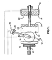
- Fig. 1 Major components of a known toroidal-race rolling-traction variator 10 are illustrated in Fig. 1.
- two input discs 12, 14 are mounted upon a drive shaft 16 for rotation therewith and have respective part toroidal surfaces 18, 20 facing toward corresponding part toroidal surfaces 22, 24 formed upon a central output disc 26.
- the output disc is journalled such as to be rotatable independently of the shaft 16.
- Drive from an engine or other prime mover, input via the shaft 16 and input discs 12, 14, is transferred to the output disc 26 via a set of rollers disposed in the toroidal cavities.
- a single representative roller 28 is illustrated but typically three such rollers are provided in both cavities.
- An end load applied across the input discs 12, 14 by a hydraulic end loading device 15 provides contact forces between rollers and discs to enable the transfer of drive.
- Each roller is mounted in a respective carriage 30 which is itself coupled to a hydraulic actuator 32 whereby a controlled translational force can be applied to the roller/carriage combination along a direction generally tangential to the main axis defined by the shaft 16.
- the actuator 32 comprises a hydraulic piston 34 capable of rotation within its cylinder 36. Such rotation of the piston is associated with a corresponding rotation (or “precession") of the roller axis about the so-called castor axis, which in the illustrated arrangement is the axis of the piston 34.
- this precession of the roller axis changes the relative diameters of the paths traced out by the roller 28 on the variator discs 12, 14, thereby changing the variator transmission ratio.
- the rollers always seek an orientation in which their axes intersect the axis of the drive shaft 16 they automatically move and precess to positions in which the so-called reaction torque is determined by the biasing force from the actuators 32.
- the Fig. 1 variator is therefore referred to as being of "torque control" type.
- the present invention is however potentially applicable to rolling-traction variators of other types including those known in the field as "part" or "half" toroidal.
- the fluid also has an important function in cooling the variator components, particularly the rollers.
- the roller operating temperature has been an important factor in determining the power capacity of the variator.
- the shearing forces in the regions of engagement between variator discs and rollers generate heat, causing the temperature of the rollers (and to a lesser extent of the discs) to rise.
- Excessive temperatures can (1) damage the rollers themselves (the steel from which they are formed undergoing changes under sustained high temperatures); and (2) impair the performance of the traction fluid, high temperatures and consequent low fluid viscosity leading to a thinner fluid layer between disc and roller, and to higher slip between these components.
- Sustained high temperatures can also cause the fluid properties to change over time in an undesirable manner.
- US-A- 5 564 993 discloses a fluid supply arrangement having the features of the preamble of claim 1, which among others include a shroud mounted in proximity to the roller.
- a fluid supply arrangement for a rolling-traction continuously-variable ratio transmission unit in which drive is transmitted from one race to another by at least one rotating roller whose outer circumference engages the races
- the fluid supply arrangement comprising a shroud mounted in proximity to the roller and a fluid supply conduit, and being characterised in that the shroud has an inner surface providing a circumferential portion adjacent the roller's outer circumference and two radially extending portions adjacent respective flanks of the roller, a fluid receiving chamber being thereby defined between the roller and the shroud, and the fluid supply conduit being arranged to deliver fluid into the fluid receiving chamber.
- a preferred embodiment of the present invention is for use in a transmission unit of toroidal race type wherein the roller is mounted in a manner allowing its inclination to alter relative to the toroidal races to thereby alter the transmission ratio, the shroud being coupled to the roller's mounting such as to maintain a constant position relative to the roller.
- Figs. 2 and 3 differs somewhat from that of Fig. 1 and its construction and operation will be briefly explained before the fluid supply arrangement itself is considered.
- Each of the three rollers 100 in the variator cavity 102 defined between variator disc 104 and its counterpart disc (omitted from Fig. 3) is mounted upon a respective carriage 106 which is acted on by two hydraulic actuators 108, 110.
- the carriages are not free to rotate to accommodate the required precession of the roller axis. Instead the orientation of the carriages is constrained.
- the center of each roller always lies on a circle 112 which is the center circle of the toroidal cavity defined by the discs, as is well known to those skilled in the art.
- any rotational movement of the carriage could only be about a carriage axis 114 (see Fig. 3) connecting the centers of the actuators 108, 110, since it is about these centers that pistons (one of which is seen at 116 in Fig. 2) provided at both ends of the carriage 106 can rotate in their cylinders such as 118.
- the carriage axis 114 is radially offset from the cavity center circle 112, as will be apparent from Fig. 3.
- the carriage axis 114 is closer to the main variator axis (defined by the main shaft 120) than the cavity center circle 112. The effect of the offset is to constrain the carriage orientation, which consequently varies only when the discs such as 104 move slightly along the main axis due to compliance and the considerable end load to which they are subject.
- each is mounted upon its carriage 106 through a bearing arrangement comprising a rotary bearing 122, which allows the roller to rotate about its own axis to transmit drive, and a ball and socket coupling upon which an inner race 126 of the rotary bearing 122 is mounted.
- a tongue seen at 124 in Fig. 3 projects from the ball 126 of this coupling into a corresponding slot in the socket, which is formed as a hub 128, to define a castor axis 130 about which the roller 100 precesses.
- a source of fluid flow such as a pump (not illustrated) is connected to a hollow stem 152 which extends along the axis of the cylinder 118 and projects into a corresponding axial bore 154 in the piston 116, forming a seal therewith.
- Bore 154 leads along an arm 156 of the carriage to a nozzle opening 158 from which fluid is projected toward the roller 100.
- a shroud 160 is juxtaposed with the roller 100.
- the roller 100 is largely surrounded by the shroud 160.
- the shroud 160 is mounted upon the hub 128 so that it remains in a fixed position relative to the roller 100 despite precession of the roller about the castor axis 130. That is, the shroud moves along with the roller. The shroud does not contact the roller 100. In the illustrated embodiment a clearance of approximately 1mm is maintained between the roller 100 and the shroud 160.
- a fluid receiving volume 161 is thus defined between the facing surfaces of the roller and the shroud 160.
- the shroud 160 has a curved circumferential wall 162 extending around the majority of the circumference of the roller 100.
- Part of the fluid receiving volume is thus formed at 163 between the outermost circumferential surface 165 of the roller and the circumferential wall 162.
- the wall is broken however in the regions 164 where the roller must contact the variator discs.
- the circumferential wall 162 is connected to the hub 128 by upper and lower walls 166, 168 lying in generally radial planes (with respect to the axis of the roller 100) at opposite faces of the roller 100. In the illustrated embodiment these are cut away in regions 170 but such cut-aways may be dispensed with.
- the shroud 160 has two fluid inlet apertures one of which is seen at 172 in Fig. 2 while the edge of the other is seen at 174. These apertures are on opposite sides of the roller. Both of the apertures 172, 174 lie on the castor axis 130 so that their displacement is minimized as the roller 100 precesses.
- both apertures 172,174 face along the castor axis 130 to receive fluid from a corresponding nozzle opening aligned therewith.
- Aperture 172 receives fluid from the aforementioned nozzle 158.
- a similarly formed nozzle feeds aperture 174 but cannot be seen in the drawings.
- the fluid must be ejected from the nozzle 158 with sufficient velocity to enter the shroud 160 despite centrifugal effects tending to expel fluid through the inlet aperture 172.
- Figs. 4 and 5 illustrate two such alternative arrangements. Many of the components are common to Figs. 2,3,4 and 5 and the same reference numerals are used for these throughout. In particular each of the arrangements has a shroud 160 containing the roller 100.
- nozzle is formed at an end 200 of an elbowed conduit 202 which is mounted as seen at 204 to the variator casing 206.
- a bore 208 in the casing 206 provides for fluid feed from a pump schematically indicated at 210.
- the conduit 202 is shaped and positioned such that it does not foul the roller 100, carriage 106 or shroud 160 as these components move.
- the inlet aperture through which fluid ejected from the nozzle 200 is in this drawing labeled 212 and again lies on, and faces along, the castor axis.
- the nozzle 200 also faces along this axis and thus remains in alignment with the inlet despite movement of the roller, although of course as the carriage 106 moves back and forth the separation of the nozzle 200 from the inlet 212 varies correspondingly.
- a further conduit 220 At the opposite side of the roller from the nozzle 200 is a further conduit 220 with a further nozzle 222.
- Fig. 5 illustrates an arrangement in which the direction along which the fluid is ejected into the shroud 160 is generally transverse to the castor axis.
- the inlet aperture 250 in the shroud 160 is in the form of a slot in the shrouds upper wall 166.
- the slot lies as close as possible to the castor axis, although the wall 166 is itself slightly displaced from this axis.
- the slot extends generally along the direction of travel of the carriage 106.
- Conduit 252 in this embodiment terminates in a nozzle 254 directed transversely to the castor axis and faces toward the inlet 250. Due to the positioning of the inlet 250 the nozzle 254 remains aligned therewith despite movement of the roller/shroud assembly.
- a possible variant of this arrangement has one of the nozzles formed as at 200 in Fig. 4 to eject fluid through an opening as at 212 onto the roller's circumference while the other nozzle, lying on the opposite side of the roller, is formed as at 254 in Fig. 5 to eject fluid onto a face of the roller. This is considered beneficial with regard to roller cooling.
- the roller itself is seen at 300 and runs on a shaft 302 rotatably carried in two sealed roller bearings 304, 306 which are themselves mounted in bores 308, 310 of respective carriage casing-halves 312, 314.
- the two casing halves are bolted together (the bolts themselves are omitted from the drawings, for simplicity) through proximal and distal intermediate carriage casing-parts 316, 318.
- the shroud is in this embodiment formed by two shroud-halves 320, 322 both having a respective radial wall 324, 326 of generally circular shape and an upstanding, circular peripheral wall 328, 329. In the assembled shroud the two peripheral walls abut, thereby defining an interior space within the shroud for containing the roller.
- the shape of the interior of the shroud is important to its function and is best seen in Fig. 8.
- the shroud's inner surface provides a circumferential, radially inwardly facing, portion 330 adjacent the roller's outer circumference, serving to restrain fluid from being centrifugally expelled from the roller.
- the separation between the roller and the shroud in this vicinity is, in the illustrated embodiment, approximately 1mm. Increased gaps, up to 4-5mm, may be used here.
- the shroud's inner surface also provides a respective generally radially extending portion 334, 336 adjacent both of the flanks 338, 340 of the roller.
- These radial portions lie, in the illustrated embodiment, in radial planes.
- the radially extending portions 334, 336 of the shroud define radial mixing chambers alongside the flanks of the roller.
- the effect of the shroud is to form a fluid receiving chamber extending around the roller's outer circumference and at least part of the roller's flanks. In this way it is found that residence time of fluid in the vicinity of the roller is greatly increased, creating improved heat transfer from the roller to the fluid and so improving roller cooling. Note that in these respects the shrouds illustrated in earlier drawings are similar.
- the shroud's peripheral wall 328, 329 can be seen to be cut away at positions 342, 344 where the roller engages the variator discs.
- a conduit for supply of cooling fluid is formed through a radial bore 346 and communicating axial bore 348 in the proximal intermediate casing part 316 (see Fig. 9).
- the axial bore leads to (1) a first radial nozzle bore 350 in the intermediate casing part 316, communicating with the fluid-receiving chamber formed between the shroud and the roller, the first nozzle bore 350 being positioned to project the fluid onto the roller's outer circumference, and (2) a pair of fluid conducting galleries 352, 354 (see Figs. 6 and 8) formed by trenches in inner faces of the respective carriage casing-halves 312, 314.
- Fluid is conducted through the galleries 352, 354 to an axially extending gallery 356 formed in the radially innermost face of the distal intermediate casing part 316, and so to a second radial nozzle bore 358 formed in the shroud wall.
- the second nozzle bore communicates with the fluid-receiving chamber and projects fluid onto the roller's circumference.
- the arrangement serves to project cooling fluid onto two regions of the roller's outer surface, one of which is diametrically opposite to the other.
- the roller/carriage assembly of Figs.6 to 9 is to be coupled to a linear actuator with provision for feeding of cooling fluid through an actuator piston.
- a suitable actuator is illustrated in Figure 10.
- the actuator construction has in fact been disclosed in our earlier US patent 5971885, the content of which is hereby incorporated by reference, and further details can be found therein.
- a cylinder 400 Within a cylinder 400 are working chambers 402,404 which receive fluid at respective pressures to act on enlarged head 408 of a piston 406.
- the piston On either side of the enlarged head 408, the piston has sleeves 410, 412 which pass sealingly through respective cylinder end walls 414, 416.
- a stem 418 is coupled to the piston through a ball and socket joint 420 at one of its ends.
- the stem's other end 422 leads to the carriage parts 316, 318, being coupled thereto, but the carriage itself is omitted from Figure 10 for the sake of simplicity.
- Traction fluid from a pump 424 is supplied through a bore 426 extending right the eay through the length of the piston and so output to the bore 346 seen in Figure 9.
Landscapes
- Engineering & Computer Science (AREA)
- General Engineering & Computer Science (AREA)
- Mechanical Engineering (AREA)
- Friction Gearing (AREA)
- General Details Of Gearings (AREA)
- Manufacturing Of Printed Circuit Boards (AREA)
- Impression-Transfer Materials And Handling Thereof (AREA)
- Separation By Low-Temperature Treatments (AREA)
Claims (14)
- Flüssigkeitszuführanordnung für eine stufenlose Reibrollengetriebeeinheit, in der Antrieb von einem Laufring zu einem anderen durch mindestens eine Drehrolle (100; 300) übertragen wird, deren äußerer Umfang die Laufringe ergreift, wobei die Flüssigkeitszuführanordnung eine Abdeckung (160; 320, 322), die in der Nähe der Rolle angebracht werden kann, und eine Flüssigkeitszuführleitung (154; 202; 252; 346, 348) aufweist und dadurch gekennzeichnet ist, dass die Abdeckung eine Innenfläche aufweist, die nach Anbringung einen Umfangsteil (162) angrenzend an den Außenumfang der Rolle und zwei radial verlaufende Teile (166, 168) angrenzend an jeweilige Flanken der Rolle bereitstellt, wodurch eine Flüssigkeitsaufnahmekammer (161) zwischen der Rolle und der Abdeckung begrenzt wird, und die Flüssigkeitszuführleitung zum Liefern von Flüssigkeit in die Flüssigkeitsaufnahmekammer eingerichtet ist.
- Flüssigkeitszuführanordnung nach Anspruch 1, bei der der Umfangsteil (162) der Innenfläche der Abdeckung um den Großteil des Rollenumfangs verläuft, der in zwei diametral gegenüberliegenden Bereichen (172, 174) weggeschnitten ist, an denen die Rolle die jeweiligen Laufringe ergreift.
- Flüssigkeitszuführanordnung nach Anspruch 1 oder Anspruch 2, bei der die Flüssigkeitszuführleitung mit der Flüssigkeitsaufnahmekammer durch mindestens eine Düse (158; 200; 254; 350, 358) kommuniziert, die zum Schleudern von Flüssigkeit auf die Rollenoberfläche eingerichtet ist.
- Flüssigkeitszuführanordnung nach Anspruch 3, bei der die Düse zum Schleudern von Flüssigkeit auf den Außenumfang der Rolle eingerichtet ist.
- Flüssigkeitszuführanordnung nach Anspruch 4, die mindestens zwei Düsen aufweist, welche zum Schleudern von Flüssigkeit auf am Umfang verteilte Bereiche des Außenumfangs der Rolle eingerichtet sind.
- Flüssigkeitszuführanordnung nach Anspruch 4, die zwei Düsen angeordnet auf diametral gegenüberliegenden Seiten der Rolle aufweist.
- Flüssigkeitszuführanordnung nach einem der Ansprüche 4 bis 6, bei der mindestens eine Düse zum Schleudern von Flüssigkeit auf eine der Rollenflanken eingerichtet ist.
- Flüssigkeitszuführanordnung nach einem vorhergehenden Anspruch, bei der die Abdeckung (320, 322) zwei Teile (324, 326) aufweist, die beide eine im wesentlichen kreisförmige radiale Wand aufweisen und um die Rolle herum zusammengebaut werden.
- Flüssigkeitszuführanordnung nach Anspruch 8, bei der mindestens einer der beiden Teile der Abdeckung eine aufrechte Umfangswand (328, 329) aufweist, die mit dem anderen der beiden Teile in Eingriff kommt.
- Flüssigkeitszuführanordnung nach einem vorhergehenden Anspruch, bei der die Abdeckung eine die Rolle enthaltende Einfassung bildet.
- Flüssigkeitszuführanordnung nach einem vorhergehenden Anspruch für eine Getriebeeinheit vom Toroidlaufringtyp, bei der die Rolle in einer Weise angebracht ist, die Änderung ihrer Neigung in Bezug zu den Toroidlaufringen zulässt, um dadurch das Übersetzungsverhältnis zu ändern, wobei die Abdeckung so an die Rollenhalterung gekoppelt ist, dass eine konstante Position in Bezug zur Rolle aufrechterhalten wird.
- Flüssigkeitszuführanordnung nach Anspruch 11, bei der die Rolle um eine Schwenkrollenachse präzedieren kann.
- Flüssigkeitszuführanordnung nach einem vorhergehenden Anspruch, bei der die Flüssigkeitszuführleitung in einer Düse endet, die positioniert und ausgerichtet ist, um Flüssigkeit durch eine Öffnung in einer Wand der Abdeckung zu schleudern, wobei die Düse von der Abdeckung getrennt ist.
- Stufenlose Reibrollengetriebeeinheit, die eine Flüssigkeitszuführanordnung nach einem vorhergehenden Anspruch aufweist.
Applications Claiming Priority (3)
| Application Number | Priority Date | Filing Date | Title |
|---|---|---|---|
| GBGB0201631.9A GB0201631D0 (en) | 2002-01-24 | 2002-01-24 | Fluid supply arrangement for a rolling-traction continuously variable ratio transmission unit |
| GB0201631 | 2002-01-24 | ||
| PCT/GB2003/000281 WO2003062675A1 (en) | 2002-01-24 | 2003-01-24 | Fluid supply arrangement for a rolling-traction continuously variable ratio transmission unit |
Publications (2)
| Publication Number | Publication Date |
|---|---|
| EP1468210A1 EP1468210A1 (de) | 2004-10-20 |
| EP1468210B1 true EP1468210B1 (de) | 2005-08-17 |
Family
ID=9929680
Family Applications (1)
| Application Number | Title | Priority Date | Filing Date |
|---|---|---|---|
| EP03701594A Expired - Lifetime EP1468210B1 (de) | 2002-01-24 | 2003-01-24 | Flüssigkeitszuführanordnung für eine stufenlose reibrollengetriebeeinheit |
Country Status (10)
| Country | Link |
|---|---|
| US (1) | US7491149B2 (de) |
| EP (1) | EP1468210B1 (de) |
| JP (1) | JP2006503230A (de) |
| CN (1) | CN100351551C (de) |
| AT (1) | ATE302367T1 (de) |
| DE (1) | DE60301328T2 (de) |
| ES (1) | ES2247512T3 (de) |
| GB (1) | GB0201631D0 (de) |
| RU (1) | RU2300031C2 (de) |
| WO (1) | WO2003062675A1 (de) |
Families Citing this family (28)
| Publication number | Priority date | Publication date | Assignee | Title |
|---|---|---|---|---|
| JP4281437B2 (ja) * | 2003-07-10 | 2009-06-17 | 株式会社日立製作所 | 記録媒体及び再生装置 |
| GB0412615D0 (en) | 2004-06-07 | 2004-07-07 | Torotrak Dev Ltd | Variator |
| JP4552555B2 (ja) * | 2004-07-30 | 2010-09-29 | 井関農機株式会社 | トラクタの変速装置 |
| JP4702600B2 (ja) * | 2005-03-22 | 2011-06-15 | 株式会社ジェイテクト | トロイダル型無段変速機 |
| GB0524795D0 (en) | 2005-12-05 | 2006-01-11 | Torotrak Dev Ltd | Variator |
| US20100031935A1 (en) * | 2008-08-05 | 2010-02-11 | Vandyne Ed | Super-turbocharger having a high speed traction drive and a continuously variable transmission |
| US8561403B2 (en) | 2008-08-05 | 2013-10-22 | Vandyne Super Turbo, Inc. | Super-turbocharger having a high speed traction drive and a continuously variable transmission |
| DE112010003185T5 (de) | 2009-08-05 | 2012-06-28 | Woodward Governor Co. | Stufenlos verstellbarer Hochdrehzahl-Traktionsantrieb |
| CN102713368B (zh) | 2009-12-16 | 2016-06-29 | 艾里逊变速箱公司 | 用于自动变速器的快速阀致动系统 |
| US8401752B2 (en) | 2009-12-16 | 2013-03-19 | Allison Transmission, Inc. | Fail-to-neutral system and method for a toroidal traction drive automatic transmission |
| EP2512892B1 (de) * | 2009-12-16 | 2019-01-09 | Allison Transmission, Inc. | System zur erkennung einer verstellerstörung |
| US8578802B2 (en) | 2009-12-16 | 2013-11-12 | Allison Transmission, Inc. | System and method for multiplexing gear engagement control and providing fault protection in a toroidal traction drive automatic transmission |
| US8676515B2 (en) * | 2009-12-16 | 2014-03-18 | Allison Transmission, Inc. | System and method for detecting clutch-related faults in an automatic transmission |
| CA2784348A1 (en) * | 2009-12-16 | 2011-06-23 | Allison Transmission, Inc. | System and method for controlling endload force of a variator |
| CA2784375C (en) * | 2009-12-16 | 2017-10-31 | Allison Transmission, Inc. | Variator lockout valve system |
| CN102822471B (zh) * | 2010-02-05 | 2015-12-16 | 万迪尼苏珀特宝公司 | 具有高速牵引驱动和连续可变变速箱的超级涡轮增压器 |
| WO2012024225A1 (en) | 2010-08-16 | 2012-02-23 | Allison Transmission, Inc. | Gear scheme for infinitely variable transmission |
| KR20140045302A (ko) | 2010-12-15 | 2014-04-16 | 알리손 트랜스미션, 인크. | 차량 변속기용 듀얼 펌프 조절기 시스템 |
| CA2821940A1 (en) | 2010-12-15 | 2012-06-21 | Allison Transmission, Inc. | Variator switching valve scheme for a torroidal traction drive transmision |
| US8721494B2 (en) | 2010-12-15 | 2014-05-13 | Allison Transmission, Inc. | Variator multiplex valve scheme for a torroidal traction drive transmision |
| US8608609B2 (en) | 2010-12-23 | 2013-12-17 | Vandyne Superturbo, Inc. | Symmetrical traction drive |
| CN103403396B (zh) | 2011-01-19 | 2016-08-24 | 范戴尼超级涡轮有限公司 | 大扭矩牵引驱动装置和传递旋转机械能的方法 |
| JP5755689B2 (ja) * | 2013-06-26 | 2015-07-29 | 川崎重工業株式会社 | トロイダル型無段変速機 |
| US9670832B2 (en) | 2013-11-21 | 2017-06-06 | Vandyne Superturbo, Inc. | Thrust absorbing planetary traction drive superturbo |
| MX364676B (es) | 2014-10-24 | 2019-05-03 | Superturbo Tech Inc | Turbocompresor accionado mediante una velocidad reducida. |
| US10107183B2 (en) | 2014-11-20 | 2018-10-23 | Superturbo Technologies, Inc. | Eccentric planetary traction drive super-turbocharger |
| CN108368931B (zh) * | 2015-12-10 | 2022-02-11 | 传输Cvt股份有限公司 | 用于环形cvt的滚轮冷却装置 |
| EP3473892A1 (de) | 2017-10-18 | 2019-04-24 | Ge Avio S.r.l. | Getriebe für einen gasturbinenmotor |
Family Cites Families (12)
| Publication number | Priority date | Publication date | Assignee | Title |
|---|---|---|---|---|
| US2132751A (en) * | 1935-04-15 | 1938-10-11 | Gen Motors Corp | Friction transmission roller lubrication |
| GB1395319A (en) * | 1971-07-27 | 1975-05-21 | Lucas Industries Ltd | Variable-ratio frictional drives |
| US3933054A (en) * | 1974-07-18 | 1976-01-20 | Sundstrand Corporation | Toroidal traction drive |
| GB1600972A (en) * | 1976-08-14 | 1981-10-21 | Lucas Industries Ltd | Variable speed transmission systems |
| GB8429823D0 (en) | 1984-11-26 | 1985-01-03 | Leyland Vehicles | Continuously variable transmission |
| IN176702B (de) * | 1988-11-21 | 1996-08-24 | Torotrak Dev Ltd | |
| GB9214190D0 (en) * | 1992-07-03 | 1992-08-12 | Robinson Leslie K | Improvements in or relating to continuously-variable-ratio transmissions of the toroidal-race rolling-traction type |
| GB9606897D0 (en) | 1996-04-01 | 1996-06-05 | Greenwood Christopher J | Roller assembly |
| JPH10132047A (ja) * | 1996-10-31 | 1998-05-22 | Jatco Corp | フルトロイダル型無段変速機 |
| GB2336633A (en) * | 1998-04-22 | 1999-10-27 | Torotrak Dev Ltd | Roller Control Unit for CVT |
| GB2336879A (en) | 1998-04-27 | 1999-11-03 | Torotrak Dev Ltd | Roller control unit for CVT |
| JP3627621B2 (ja) | 2000-05-19 | 2005-03-09 | 日産自動車株式会社 | トロイダル型無段変速機 |
-
2002
- 2002-01-24 GB GBGB0201631.9A patent/GB0201631D0/en not_active Ceased
-
2003
- 2003-01-24 DE DE60301328T patent/DE60301328T2/de not_active Expired - Lifetime
- 2003-01-24 ES ES03701594T patent/ES2247512T3/es not_active Expired - Lifetime
- 2003-01-24 AT AT03701594T patent/ATE302367T1/de not_active IP Right Cessation
- 2003-01-24 RU RU2004125652/11A patent/RU2300031C2/ru active
- 2003-01-24 JP JP2003562510A patent/JP2006503230A/ja active Pending
- 2003-01-24 WO PCT/GB2003/000281 patent/WO2003062675A1/en not_active Ceased
- 2003-01-24 EP EP03701594A patent/EP1468210B1/de not_active Expired - Lifetime
- 2003-01-24 CN CNB038024837A patent/CN100351551C/zh not_active Expired - Lifetime
- 2003-01-24 US US10/497,566 patent/US7491149B2/en not_active Expired - Lifetime
Also Published As
| Publication number | Publication date |
|---|---|
| RU2004125652A (ru) | 2005-04-27 |
| DE60301328T2 (de) | 2006-06-01 |
| CN100351551C (zh) | 2007-11-28 |
| GB0201631D0 (en) | 2002-03-13 |
| US7491149B2 (en) | 2009-02-17 |
| RU2300031C2 (ru) | 2007-05-27 |
| US20050143216A1 (en) | 2005-06-30 |
| DE60301328D1 (de) | 2005-09-22 |
| WO2003062675A1 (en) | 2003-07-31 |
| JP2006503230A (ja) | 2006-01-26 |
| EP1468210A1 (de) | 2004-10-20 |
| ES2247512T3 (es) | 2006-03-01 |
| ATE302367T1 (de) | 2005-09-15 |
| CN1620567A (zh) | 2005-05-25 |
Similar Documents
| Publication | Publication Date | Title |
|---|---|---|
| EP1468210B1 (de) | Flüssigkeitszuführanordnung für eine stufenlose reibrollengetriebeeinheit | |
| ES2643067T3 (es) | Motor de tracción toroidal total | |
| EP0930449B1 (de) | Rolleranordnung für Betätigungskolben | |
| JP4153991B2 (ja) | 連続変速油圧トランスミッション | |
| CN101657653A (zh) | 无级变速器及其方法 | |
| JPH02191892A (ja) | 圧力伝達装置 | |
| KR100361873B1 (ko) | 차동장치 | |
| NZ200819A (en) | Vane type fluid motor or pump with positively pressure-controlled vane/cam contact | |
| KR100652279B1 (ko) | 가변토크의 전달장치 및, 가변토크와 가변속도비율을 위한 변속기. | |
| US6203467B1 (en) | Lubricating mechanism of toroidal continuously variable transmission | |
| US20160102750A1 (en) | Toroidal-type stepless transmission | |
| JP4144063B2 (ja) | トロイダル型無段変速機の潤滑装置 | |
| US7001305B2 (en) | Toroidal type continuously variable transmission | |
| JP4190117B2 (ja) | トロイダル型無段変速機 | |
| KR20080073334A (ko) | 가변기 | |
| US5495713A (en) | Hydrostatic differential transmission | |
| JP2001254795A (ja) | トロイダル型無段変速機 | |
| EP1148270A1 (de) | Stufenlos verstellbares Getriebe | |
| JP3643937B2 (ja) | ベーンポンプ | |
| JP4702600B2 (ja) | トロイダル型無段変速機 | |
| JP3717347B2 (ja) | トロイダル型無段変速機 | |
| JP3572437B2 (ja) | トロイダル型無段変速機 | |
| US20260015072A1 (en) | Marine drive unit | |
| CA1184431A (en) | Rotary pump or motor with drive rollers and free- floating rollers | |
| JP2004536246A (ja) | 予言された故障モードのためのベーンポンプ磨耗センサ |
Legal Events
| Date | Code | Title | Description |
|---|---|---|---|
| PUAI | Public reference made under article 153(3) epc to a published international application that has entered the european phase |
Free format text: ORIGINAL CODE: 0009012 |
|
| 17P | Request for examination filed |
Effective date: 20040527 |
|
| AK | Designated contracting states |
Kind code of ref document: A1 Designated state(s): AT BE BG CH CY CZ DE DK EE ES FI FR GB GR HU IE IT LI LU MC NL PT SE SI SK TR |
|
| AX | Request for extension of the european patent |
Extension state: AL LT LV MK RO |
|
| GRAP | Despatch of communication of intention to grant a patent |
Free format text: ORIGINAL CODE: EPIDOSNIGR1 |
|
| RIN1 | Information on inventor provided before grant (corrected) |
Inventor name: GREENWOOD, CHRISTOPHER JOHN Inventor name: MACPHERSON, IAN Inventor name: FLAXMAN, ROBERT JOHN BONNER Inventor name: BRIFFETT, GRAHAM |
|
| GRAS | Grant fee paid |
Free format text: ORIGINAL CODE: EPIDOSNIGR3 |
|
| GRAA | (expected) grant |
Free format text: ORIGINAL CODE: 0009210 |
|
| AK | Designated contracting states |
Kind code of ref document: B1 Designated state(s): AT BE BG CH CY CZ DE DK EE ES FI FR GB GR HU IE IT LI LU MC NL PT SE SI SK TR |
|
| PG25 | Lapsed in a contracting state [announced via postgrant information from national office to epo] |
Ref country code: BE Free format text: LAPSE BECAUSE OF FAILURE TO SUBMIT A TRANSLATION OF THE DESCRIPTION OR TO PAY THE FEE WITHIN THE PRESCRIBED TIME-LIMIT Effective date: 20050817 Ref country code: TR Free format text: LAPSE BECAUSE OF FAILURE TO SUBMIT A TRANSLATION OF THE DESCRIPTION OR TO PAY THE FEE WITHIN THE PRESCRIBED TIME-LIMIT Effective date: 20050817 Ref country code: SK Free format text: LAPSE BECAUSE OF FAILURE TO SUBMIT A TRANSLATION OF THE DESCRIPTION OR TO PAY THE FEE WITHIN THE PRESCRIBED TIME-LIMIT Effective date: 20050817 Ref country code: SI Free format text: LAPSE BECAUSE OF FAILURE TO SUBMIT A TRANSLATION OF THE DESCRIPTION OR TO PAY THE FEE WITHIN THE PRESCRIBED TIME-LIMIT Effective date: 20050817 Ref country code: LI Free format text: LAPSE BECAUSE OF FAILURE TO SUBMIT A TRANSLATION OF THE DESCRIPTION OR TO PAY THE FEE WITHIN THE PRESCRIBED TIME-LIMIT Effective date: 20050817 Ref country code: CZ Free format text: LAPSE BECAUSE OF FAILURE TO SUBMIT A TRANSLATION OF THE DESCRIPTION OR TO PAY THE FEE WITHIN THE PRESCRIBED TIME-LIMIT Effective date: 20050817 Ref country code: NL Free format text: LAPSE BECAUSE OF FAILURE TO SUBMIT A TRANSLATION OF THE DESCRIPTION OR TO PAY THE FEE WITHIN THE PRESCRIBED TIME-LIMIT Effective date: 20050817 Ref country code: EE Free format text: LAPSE BECAUSE OF FAILURE TO SUBMIT A TRANSLATION OF THE DESCRIPTION OR TO PAY THE FEE WITHIN THE PRESCRIBED TIME-LIMIT Effective date: 20050817 Ref country code: AT Free format text: LAPSE BECAUSE OF FAILURE TO SUBMIT A TRANSLATION OF THE DESCRIPTION OR TO PAY THE FEE WITHIN THE PRESCRIBED TIME-LIMIT Effective date: 20050817 Ref country code: CH Free format text: LAPSE BECAUSE OF FAILURE TO SUBMIT A TRANSLATION OF THE DESCRIPTION OR TO PAY THE FEE WITHIN THE PRESCRIBED TIME-LIMIT Effective date: 20050817 |
|
| REG | Reference to a national code |
Ref country code: GB Ref legal event code: FG4D |
|
| REG | Reference to a national code |
Ref country code: CH Ref legal event code: EP |
|
| REG | Reference to a national code |
Ref country code: IE Ref legal event code: FG4D |
|
| REF | Corresponds to: |
Ref document number: 60301328 Country of ref document: DE Date of ref document: 20050922 Kind code of ref document: P |
|
| PG25 | Lapsed in a contracting state [announced via postgrant information from national office to epo] |
Ref country code: BG Free format text: LAPSE BECAUSE OF FAILURE TO SUBMIT A TRANSLATION OF THE DESCRIPTION OR TO PAY THE FEE WITHIN THE PRESCRIBED TIME-LIMIT Effective date: 20051117 Ref country code: DK Free format text: LAPSE BECAUSE OF FAILURE TO SUBMIT A TRANSLATION OF THE DESCRIPTION OR TO PAY THE FEE WITHIN THE PRESCRIBED TIME-LIMIT Effective date: 20051117 Ref country code: SE Free format text: LAPSE BECAUSE OF FAILURE TO SUBMIT A TRANSLATION OF THE DESCRIPTION OR TO PAY THE FEE WITHIN THE PRESCRIBED TIME-LIMIT Effective date: 20051117 Ref country code: GR Free format text: LAPSE BECAUSE OF FAILURE TO SUBMIT A TRANSLATION OF THE DESCRIPTION OR TO PAY THE FEE WITHIN THE PRESCRIBED TIME-LIMIT Effective date: 20051117 |
|
| PG25 | Lapsed in a contracting state [announced via postgrant information from national office to epo] |
Ref country code: PT Free format text: LAPSE BECAUSE OF FAILURE TO SUBMIT A TRANSLATION OF THE DESCRIPTION OR TO PAY THE FEE WITHIN THE PRESCRIBED TIME-LIMIT Effective date: 20060117 |
|
| PG25 | Lapsed in a contracting state [announced via postgrant information from national office to epo] |
Ref country code: IE Free format text: LAPSE BECAUSE OF NON-PAYMENT OF DUE FEES Effective date: 20060124 |
|
| PG25 | Lapsed in a contracting state [announced via postgrant information from national office to epo] |
Ref country code: MC Free format text: LAPSE BECAUSE OF NON-PAYMENT OF DUE FEES Effective date: 20060131 Ref country code: LU Free format text: LAPSE BECAUSE OF NON-PAYMENT OF DUE FEES Effective date: 20060131 |
|
| NLV1 | Nl: lapsed or annulled due to failure to fulfill the requirements of art. 29p and 29m of the patents act | ||
| PG25 | Lapsed in a contracting state [announced via postgrant information from national office to epo] |
Ref country code: HU Free format text: LAPSE BECAUSE OF FAILURE TO SUBMIT A TRANSLATION OF THE DESCRIPTION OR TO PAY THE FEE WITHIN THE PRESCRIBED TIME-LIMIT Effective date: 20060218 |
|
| REG | Reference to a national code |
Ref country code: CH Ref legal event code: PL |
|
| REG | Reference to a national code |
Ref country code: ES Ref legal event code: FG2A Ref document number: 2247512 Country of ref document: ES Kind code of ref document: T3 |
|
| ET | Fr: translation filed | ||
| PLBE | No opposition filed within time limit |
Free format text: ORIGINAL CODE: 0009261 |
|
| STAA | Information on the status of an ep patent application or granted ep patent |
Free format text: STATUS: NO OPPOSITION FILED WITHIN TIME LIMIT |
|
| 26N | No opposition filed |
Effective date: 20060518 |
|
| REG | Reference to a national code |
Ref country code: IE Ref legal event code: MM4A |
|
| PG25 | Lapsed in a contracting state [announced via postgrant information from national office to epo] |
Ref country code: CY Free format text: LAPSE BECAUSE OF FAILURE TO SUBMIT A TRANSLATION OF THE DESCRIPTION OR TO PAY THE FEE WITHIN THE PRESCRIBED TIME-LIMIT Effective date: 20050817 |
|
| PGFP | Annual fee paid to national office [announced via postgrant information from national office to epo] |
Ref country code: FI Payment date: 20140113 Year of fee payment: 12 |
|
| REG | Reference to a national code |
Ref country code: FR Ref legal event code: PLFP Year of fee payment: 13 |
|
| PG25 | Lapsed in a contracting state [announced via postgrant information from national office to epo] |
Ref country code: FI Free format text: LAPSE BECAUSE OF NON-PAYMENT OF DUE FEES Effective date: 20150124 |
|
| REG | Reference to a national code |
Ref country code: FR Ref legal event code: PLFP Year of fee payment: 14 |
|
| REG | Reference to a national code |
Ref country code: FR Ref legal event code: PLFP Year of fee payment: 15 |
|
| REG | Reference to a national code |
Ref country code: FR Ref legal event code: PLFP Year of fee payment: 16 |
|
| REG | Reference to a national code |
Ref country code: ES Ref legal event code: PC2A Effective date: 20180530 Ref country code: ES Ref legal event code: PC2A Owner name: ALLISON TRANSMISSION, INC. Effective date: 20180530 |
|
| REG | Reference to a national code |
Ref country code: FR Ref legal event code: TP Owner name: ALLISON TRANSMISSION, INC., US Effective date: 20181004 |
|
| REG | Reference to a national code |
Ref country code: DE Ref legal event code: R081 Ref document number: 60301328 Country of ref document: DE Owner name: ALLISON TRANSMISSION, INC., INDIANAPOLIS, US Free format text: FORMER OWNER: TOROTRAK (DEVELOPMENT) LTD., LEYLAND, LANCASHIRE, GB Ref country code: DE Ref legal event code: R082 Ref document number: 60301328 Country of ref document: DE Representative=s name: MITSCHERLICH, PATENT- UND RECHTSANWAELTE PARTM, DE |
|
| REG | Reference to a national code |
Ref country code: GB Ref legal event code: 732E Free format text: REGISTERED BETWEEN 20190117 AND 20190123 |
|
| PGFP | Annual fee paid to national office [announced via postgrant information from national office to epo] |
Ref country code: GB Payment date: 20220127 Year of fee payment: 20 Ref country code: DE Payment date: 20220127 Year of fee payment: 20 |
|
| PGFP | Annual fee paid to national office [announced via postgrant information from national office to epo] |
Ref country code: IT Payment date: 20220119 Year of fee payment: 20 Ref country code: FR Payment date: 20220125 Year of fee payment: 20 Ref country code: ES Payment date: 20220201 Year of fee payment: 20 |
|
| REG | Reference to a national code |
Ref country code: DE Ref legal event code: R071 Ref document number: 60301328 Country of ref document: DE |
|
| REG | Reference to a national code |
Ref country code: GB Ref legal event code: PE20 Expiry date: 20230123 |
|
| REG | Reference to a national code |
Ref country code: ES Ref legal event code: FD2A Effective date: 20230428 |
|
| PG25 | Lapsed in a contracting state [announced via postgrant information from national office to epo] |
Ref country code: GB Free format text: LAPSE BECAUSE OF EXPIRATION OF PROTECTION Effective date: 20230123 |
|
| P01 | Opt-out of the competence of the unified patent court (upc) registered |
Effective date: 20230521 |
|
| PG25 | Lapsed in a contracting state [announced via postgrant information from national office to epo] |
Ref country code: ES Free format text: LAPSE BECAUSE OF EXPIRATION OF PROTECTION Effective date: 20230125 |