EP1468342B1 - Procede de determination de la position d'un appareil automatique sur roues - Google Patents
Procede de determination de la position d'un appareil automatique sur roues Download PDFInfo
- Publication number
- EP1468342B1 EP1468342B1 EP03731868A EP03731868A EP1468342B1 EP 1468342 B1 EP1468342 B1 EP 1468342B1 EP 03731868 A EP03731868 A EP 03731868A EP 03731868 A EP03731868 A EP 03731868A EP 1468342 B1 EP1468342 B1 EP 1468342B1
- Authority
- EP
- European Patent Office
- Prior art keywords
- wheel
- distance
- value
- robot
- planes
- Prior art date
- Legal status (The legal status is an assumption and is not a legal conclusion. Google has not performed a legal analysis and makes no representation as to the accuracy of the status listed.)
- Expired - Lifetime
Links
- 238000000034 method Methods 0.000 title claims abstract description 62
- 238000004364 calculation method Methods 0.000 claims description 2
- 239000007787 solid Substances 0.000 description 4
- 238000004140 cleaning Methods 0.000 description 2
- 238000013459 approach Methods 0.000 description 1
- 238000001514 detection method Methods 0.000 description 1
- 239000000428 dust Substances 0.000 description 1
- 238000004519 manufacturing process Methods 0.000 description 1
- 238000005096 rolling process Methods 0.000 description 1
Images


Classifications
-
- G—PHYSICS
- G01—MEASURING; TESTING
- G01S—RADIO DIRECTION-FINDING; RADIO NAVIGATION; DETERMINING DISTANCE OR VELOCITY BY USE OF RADIO WAVES; LOCATING OR PRESENCE-DETECTING BY USE OF THE REFLECTION OR RERADIATION OF RADIO WAVES; ANALOGOUS ARRANGEMENTS USING OTHER WAVES
- G01S15/00—Systems using the reflection or reradiation of acoustic waves, e.g. sonar systems
- G01S15/88—Sonar systems specially adapted for specific applications
- G01S15/93—Sonar systems specially adapted for specific applications for anti-collision purposes
- G01S15/931—Sonar systems specially adapted for specific applications for anti-collision purposes of land vehicles
-
- A—HUMAN NECESSITIES
- A47—FURNITURE; DOMESTIC ARTICLES OR APPLIANCES; COFFEE MILLS; SPICE MILLS; SUCTION CLEANERS IN GENERAL
- A47L—DOMESTIC WASHING OR CLEANING; SUCTION CLEANERS IN GENERAL
- A47L2201/00—Robotic cleaning machines, i.e. with automatic control of the travelling movement or the cleaning operation
- A47L2201/04—Automatic control of the travelling movement; Automatic obstacle detection
Definitions
- the present invention relates to a method and the use of a method for position determination of an automatic apparatus on wheels, such as a robotic vacuum cleaner.
- At least one wheel on the apparatus comprises at least one wheel sensor that recognizes the rotation of said wheel.
- the apparatus also comprises at least one room sensor detecting objects in the space surrounding the apparatus.
- Robots Automatic apparatus on wheels, so called robots, are products that during the recent years have increased in importance and interest. Earlier they have been used in industries, professionally, mainly for manufacture tasks. Some of these robots have had features in order to been able to navigate and move in the environment and detect objects in the surrounding area. During the recent years consumer aspects has reached into the robotic area and the features such as for navigation is of interest for the consumers.
- a magnetic strip following robot may also have the capacity of detecting if it collides with anything, such as an obstacle or the object that it is intended to work with. In order to sense such collisions sensors, which sense physical contact could be used.
- the robot can use a navigation system that relies on detecting sensors, such as IR (infrared) or Ultrasonic sensors. These sensors can detect objects in its surroundings by transmitting and receiving reflected signals. By using these types of sensors the direction and distance to the sensors can be estimated. In order to manage that, the sensors have to be mounted on the robot and controlled in a proper way.
- detecting sensors such as IR (infrared) or Ultrasonic sensors.
- IR infrared
- Ultrasonic sensors can detect objects in its surroundings by transmitting and receiving reflected signals.
- the direction and distance to the sensors can be estimated.
- the sensors have to be mounted on the robot and controlled in a proper way.
- EP0835459 is disclosed in the European Patent EP0835459.
- the robot is often equipped with wheel sensor detecting the rotation on each wheel. These sensors sense the wheel rotation and are calibrated regularly in order to take into consideration the distance between the wheels and the wheel dimensions.
- Wall following is a method that use this kind of wheel sensing system. In this method, the robot starts its operation by following the walls around the room. When this is completed, the robot estimates the size of the room, at least based on information from the wheel sensors, and starts navigating inside the room at least using information from said wheel sensors.
- SLAM calculates the robot position based on the relation in position between the robot and an object.
- a sensor system with Ultrasonic or IR can be used.
- SLAM builds a map of the room inside which the robot navigates. By using a specific algorithm the position of the robot is estimated.
- SLAM is used together with a sensor system that only detects objects in its presence, the method gets difficulties in its estimations. If there are no detectable objects near the robot, this will cause SLAM to fail or work with higher uncertainty because SLAM has too few objects to work with.
- a way for solving this problem is to improve the capacity of the sensor system. However, all such improvements cost money, which results in more expensive products for the consumer.
- the object of the present invention is therefore to achieve a navigation method for a regular robot, which method should be quite reliable and easy to use without the need of expensive components.
- the method intends to be used in robots, such as robotic vacuum cleaners, in order to improve its operation capacity.
- the present invention therefore relates to a method according to claim 1 and the use of a method for position determination of an automatic apparatus on wheels, such as a robotic vacuum cleaner according to claim 20.
- At least one wheel on the apparatus comprises at least one wheel sensor that recognizes the rotation of said wheel.
- the apparatus also comprises at least one room sensor detecting objects in the space surrounding the apparatus.
- the position determination is accomplished at least by using one wheel sensor and estimate the substantial, horizontal extension direction of substantially vertical planes on the objects, which planes are defined by the apparatus, whereby the substantial, actual position of the apparatus is determined using at least one predetermined assumption on the relationship between the extension direction of different planes.
- the method is using wheel sensors for position determination and together with that uses predetermined assumptions on characteristics for surrounding planes defined by the apparatus, the information and equipment needed is cheaper.
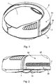
- Fig. 1 shows a perspective view of a robot at which the method of the present invention is applied.
- Fig. 2 shows a side view of the robot according to fig. 1.
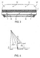
- Fig. 3 shows a front view of the robot according to fig. 1.
- Fig. 4 shows a graph of how the sensor system of the robot according to fig. 1 detects is surroundings.
- Fig. 5 shows a simplified flow chart of the method according to the present invention.
- Fig. 6 shows a simplified view of how the method according to the present invention estimates its current position.
- Fig. 7 shows how the estimation according to fig. 6 is partly made.
- Fig. 1 - 3 shows an illustrative example of a robot together with which the method according to the present invention can be used.
- the features and navigation system of the robot are initially described. Thereafter, an illustrative embodiment of the method according to the present invention is described.
- Fig. 1 - 3 shows an automatic vacuum cleaner robot.
- the robot shape is circular and it is supported by two driving wheels 1 together with a front supporting wheel (not shown).
- the driving wheels are made in order to achieve the best possible friction against the floor.
- the two driving wheels are controlled in order to move the robot in any direction over the floor on which it operates.
- Each driving wheel therefore is connected to an electric motor, eventually via a gear, which motor is controlled by a control unit, whereby the unit brings the robot into movement.
- the robot also comprises a brush roller (not shown) as a part of the floor-cleaning feature. This cleaning feature will not be described any further, since its function is not important for the scope of the present invention.
- the robot has wheel sensors (not shown) that detect the wheel rotation on each of the two driving wheels 1.
- the dimension of each driving wheel is stored in connection to the control unit.
- a calibration method further described in the published Swedish patent application 0100925-7 is used. The method calculates the navigation route of the robot taking into consideration the variations in distance between the two driving wheels. This variation is assumed to depend on if and how much the robot turns. By dividing the robot movement into different modes related to different values of wheel distances, each mode could be properly used in order to estimate the movement of the robot in relation to the floor.
- the robot In order for the robot to detect objects in its surroundings it is equipped with a sensor system. Thereby, the robot can detect the objects, perform estimating calculations of their position in relation to the robot, and thereafter control the movement of the robot as wished. One controlled movement could be to bring the robot into a slower motion as it approaches the object. Another option is to enable a more effective navigation route. Such an option is disclosed in the published Swedish Patent application 0100924-0. When navigating the robot divides the floor surface into cells, each cell being connected with a value that is re-evaluated as the robot moves. The navigation route is decided depending on which value the cells near the robot have.
- the visible outer parts of the sensor system of the robot are shown in fig. 1 - 3.
- the system uses ultrasonic signals in order to detect obstacles and objects in its surroundings.
- One transmitter 2 stretches along the front side of the robot.
- the transmitter transmits ultrasonic signals that spread out both horizontally and vertically.
- Microphones 3a - 3e and 4a - 4d are placed along the front side and receives the transmitted signals reflected by an object or obstacle.
- fig. 4 it is shown how the system detects one point in the object.
- "mik 1 - 5" for example corresponds to the microphones 3a - 3e.
- Solid-drawn lines in fig. 4 relates to the reflected signals detected by the microphones 3a - 3e.
- the system detects one point at a time. Knowing about how the transmitter 2 and the microphones are oriented and the characteristics of the ultrasonic signal the robot can estimate the distance and direction to a detected point on an object.
- a free moving and hanging front part 6 which the robot uses in order to detect a direct collision with an obstacle or object is shown.
- the front part moves when getting in contact with an object and affects micro switches or other motion detectors behind the front part.
- An over part 7 under which a dust collecting container is mounted is also shown in the figure.
- the robot uses the wall following behaviour, as described earlier in this document.
- the robot first starts seeking up a wall, see fig. 6. Thereafter, the robot follows the walls that surround the room all the way around until it has reached back to its original wall following position.
- the wheel sensors detect the motion and calculate the position of the robot. Based on the wall following, the robot creates a map of the room.
- the sensor system is uses in order to control that a wall is followed.
- fig. 6 the positions of the robot, estimated by the wheel sensors on the robot, are shown as a dotted line 8.
- the actual position of the robot is shown as the solid-drawn line 9.
- the outer frame 10 of the figure corresponds to the surrounding walls and the two black areas 11,12 corresponds to obstacles in the room area. Since the sensor system detects the walls and obstacles it is possible to achieve a working wall following behaviour.
- the wall following behaviour shown in fig. 6 constitutes the frame of the method according to the present invention.
- a problem with the wall following behaviour is that the position of the robot is estimated based on the wheel sensors. Since the movement of the wheels is not definitely related to the movement of the robot in relation to the floor, an error is created in the position estimation. Shown as the dotted line 8 in fig. 6. The actual movement, shown as the solid-drawn line 9, is created since the robot in reality is following the walls.
- an error is added to the estimated position, which causes the total error of the estimation to increase as the robot movement proceeds.
- the invention method uses the wall following behaviour. Also, the method according to the present invention assumes a relation in horizontal extension direction between the walls or between walls and other larger objects in the area (room) in which the robot operates.
- the assumption is based on the fact that walls are normally perpendicular to each other. Other angles, such as 30° (DEG), 45° or 60°, are common in modern rooms and can also be taken into the assumption.
- perpendicular and parallel walls are of most interest, but the present invention shall be read taking the other wall angle relations in consideration.
- the assumption is that these are normally placed perpendicular or in parallel with a wall. They may also be placed in 30°, 45° or 60° relations to a wall.
- the position of the robot estimated 8 based on information from the wheel sensors, is to be corrected into the correct position 9.
- the method compares the estimated direction when the robot follows a first wall or larger object with the estimated direction when the robot follows a second wall.
- the errors cause these estimated directions to differ from each other with more or less than 90°, 180°, 270°, 360° (for the perpendicular or parallel objects or walls). Knowing that there is a difference between the estimated value and the assumption value gives the robot information, which enables it to correct the estimated position. Referring to fig. 6, the estimated route shown as the dotted line 8 will be corrected into the actual route, shown as solid-drawn line 9. Later, a new correction can be accomplished if the estimated position is shown to again differ.
- a wall following using the method of the preferred embodiment is regularly performed.
- Wall following is accomplished by the sensor system, in which the transmitter 2 and the microphones 3a - 3e, 4a - 4d detects and makes sure that the robot can follow a wall or any other plane detected by the sensor system.
- a detected plane could relate to a solid furniture wall side or a virtual wall sides defined and created by the sensor system, which virtual wall for example extends between the legs of a large sofa.
- the method according to the invention is not intended to be limited to which kind of walls the robot can see and define, but to the fact that the robot starts a wall following procedure following of any wall or plane.
- any wall or furniture side followed will from now on be defined as a plane defined by the robot, whether or not it is a solid wall or a virtual wall.
- the robot moves in parallel with the plane it continuously detects or for virtual walls assumes points on the plane, and if the distance remains substantially constant the FollowingStraightWall is set. The distance must also remain within a certain threshold value, for example 5 centimetres. The threshold value will cause the robot to detect if a wall is ended. For virtual walls this continues distance detection is not real and therefore the distance control will work differently, not described here. The idea with this distance idea is to investigate if a solid wall is followed properly.
- DEG 3°
- the threshold angle relates to the difference in the moving direction on two different moments after one another.
- a second threshold value of for example 5° (DEG) is set that relates to the difference in moving direction between the direction registered at the moment of FollowingStraightWall and the direction registered at the last moment when a plane ends or the robot stops following a wall, at endWallEncountered.
- This second threshold value is set in order to detect if the plane followed was straight or curved.
- a virtual wall normally will be followed without angle divergences, which means that such a control for virtual walls works differently.
- endWallEncountered When one of these threshold values is exceeded endWallEncountered is set. Thereafter the moving distance between FollowingStraightwall and endWallEncountered is registered. This distance corresponds to the length l of the plane, which corresponds to the wall 10 or larger object 11,12 along which the robot has moved. If l is larger or equal to minLength, for example set to 80 centimetres, the essential extension direction ⁇ of the defined plane followed and the extension length ⁇ of the same plane is calculated with a Hugh Transform (not shown or described here) and stored. Both values are calculated based on the information registered by the wheel sensors. Considering virtual walls, endWallEncountered will be set based on other control aspects as mentioned earlier. How this is done will not be described any further in this application. The important thing is that endWallEncountered is set also for virtual walls when the wall following of those fulfil certain demands, and that the distance demands controlled after endWallencountered will be evaluated also for the virtual walls.
- ⁇ is set as RefAngle. This means a moment when the robot starts operating or is set to do a new wall following procedure.
- the angle ⁇ will be compared with RefAngle. During this comparison the difference will be compensated for the assumption angles 90°, 180°, 270°, 360° mentioned above. This means that if the difference is 93°, 90° will be subtracted and a result difference value of +/- 3° will come out, defined as Rdiff. If it is shown, during this comparing, that Rdiff has a value that is not zero it also needs to stay within a threshold value angleTh.
- the threshold value angleTh is not definite but continuously recalculated based on the uncertainty registered during earlier adjustments done by the method according to the invention. Its maximum value is 25° in case the assumption is that only the angle relation between two defined planes are 90°, 180°, 270° or 360°.
- angleTh should be lower in order for the method to work satisfying. Rdiff will thereby be compensated based also on these assumption angles.
- the compensated Rdiff is finally used in order to adjust the position estimated by the robot wheel sensors.
- the new position is calculated as an adjustment of the angle caused by the difference in the estimated and actual angle relation between two defined planes.
- the estimated angle refers to the extension direction of the defined plane that the robot moved along between FollowingStraightWall and endWallEncountered.
- the solid-drawn line 13 relates to the actual extension direction of the defined plane, such as the wall or furniture side.
- the dotted line 14 relates the estimated extension direction of that plane, estimated based on information form the wheel sensors.
- the thinner solid-drawn line 15 relates to the correction of the estimated direction, where "K" is the correction and corresponds to Rdiff, the direction of Rdiff taken into consideration.
- the adjusted direction may then be used as reference in the method algorithm and compared with the next estimated plane direction under the assumption that these should be related in perpendicular or parallel to each other.
- the invention is not limited by the fact that the robot needs to have a room sensor system using IR or Ultrasonic signals in order to accomplish a wall following behaviour.
- Any kind of solutions such as wheel rolling on the wall or any other solution close in fact for the person skilled in the art can be used.
- the only demand is that any selected solution can accomplish and detect a wall following behaviour, where walls correspond to any plane defined by the robot.
Landscapes
- Engineering & Computer Science (AREA)
- Radar, Positioning & Navigation (AREA)
- Remote Sensing (AREA)
- Physics & Mathematics (AREA)
- Acoustics & Sound (AREA)
- Computer Networks & Wireless Communication (AREA)
- General Physics & Mathematics (AREA)
- Control Of Position, Course, Altitude, Or Attitude Of Moving Bodies (AREA)
- Manipulator (AREA)
- Die Bonding (AREA)
- Container, Conveyance, Adherence, Positioning, Of Wafer (AREA)
- Apparatuses And Processes For Manufacturing Resistors (AREA)
Claims (20)
- Procédé de détermination de position d'un appareil automatique sur roues (1), au moins une roue comprenant au moins un capteur de roue qui reconnaît la rotation de ladite roue (1), ledit appareil comprenant également au moins un capteur d'environnement (2, 3a-3e, 4a-4d) qui détecte des objets dans l'espace entourant l'appareil, caractérisé par les étapes consistant à :estimer la direction de déplacement, la vitesse de déplacement et la position estimée de l'appareil au moins en utilisant des informations émanant d'au moins un capteur de roue ;estimer une direction d'extension horizontale substantielle (14) de plans sensiblement verticaux (13) sur les objets (10 à 12), lesdits plans (13) étant définis par l'appareil en utilisant des informations émanant dudit au moins un capteur d'environnement (2, 3a-3e, 4a-4d) ; etdéterminer la position réelle substantielle de l'appareil en utilisant au moins une supposition prédéterminée de la relation entre la direction d'extension (15) de différents plans (13), dans lequel lesdites directions d'extension (15) des plans définis (13) sont reconnues en utilisant au moins l'un des capteurs d'environnement (2, 3a-3e, 4a-4d) et en détectant si la direction de déplacement (9) de l'appareil est sensiblement parallèle à la direction d'extension (15) d'au moins l'un desdits plans définis (13).
- Procédé selon la revendication 1, caractérisé en ce que l'estimation est également accomplie en utilisant des informations stockées sur la dimension de roue et des informations sur la distance entre les roues (1), ladite distance pouvant être déterminée en utilisant un procédé de calcul de calibre de piste.
- Procédé selon la revendication 2, caractérisé en ce que le procédé de calcul de distance de roue comprend un calcul récurrent de la distance sur la base des informations de dimension de roue et des informations de position des objets par rapport à l'appareil.
- Procédé selon l'une quelconque des revendications précédentes, caractérisé en ce que la distance entre l'appareil et un objet est reconnue en utilisant des informations émanant d'au moins un capteur d'environnement (2, 3a-3e, 4a-4d).
- Procédé selon l'une quelconque des revendications précédentes, caractérisé en ce qu'au moins l'un des capteurs d'environnement (2, 3a-3e, 4a-4d) utilise des signaux ultrasonores pour détecter un objet.
- Procédé selon l'une quelconque des revendications précédentes, caractérisé en ce qu'au moins l'un des capteurs d'environnement (2, 3a-3e, 4a-4d) utilise des moyens de détection mécaniques pour détecter si l'appareil est en contact avec un objet.
- Procédé selon l'une quelconque des revendications précédentes, caractérisé en ce que lorsque ledit déplacement parallèle (9) est détecté, la direction de déplacement R0 de l'appareil est au début détectée à un premier moment TD0 puis, aux moments suivants TD1 à TDn, la direction de déplacement R1 à Rn est également détectée.
- Procédé selon la revendication 7, caractérisé en ce qu'au moins l'un des capteurs d'environnement (2, 3a-3e, 4a-4d) à un premier moment TDend après TD0 détecte que la distance entre l'appareil et le plan défini (13), ledit appareil se déplaçant sensiblement parallèlement audit plan, diverge de certaines exigences de distances stockées ou établies par l'appareil et/ou au moins l'un des capteurs de roue à un premier moment TDend après TD0 détecte que la direction de déplacement Rend de l'appareil diverge de certaines exigences de directions stockées ou de certaines exigences de directions établies par l'appareil, et/ou s'il est détecté à un premier moment TDend après TD0 qu'un plan défini répond à certaines exigences, une mesure de la distance de déplacement de l'appareil comptée de TD0 à TDend est effectuée, ladite distance étant calculée et stockée.
- Procédé selon la revendication 8, caractérisé en ce que l'exigence de direction correspond à l'exigence selon laquelle la valeur absolue de la différence entre Rend et R0 est supérieure à une certaine première valeur de direction et/ou la valeur absolue de la différence entre Rend et la direction de déplacement détectée à un moment après TD0 mais avant TDend est supérieure à une certaine seconde valeur de direction.
- Procédé selon la revendication 9, caractérisé en ce que la première valeur de direction est réglée à 5° (degrés) et la seconde valeur de direction est réglée à 3° (degrés).
- Procédé selon l'une quelconque des revendications 8 à 10, caractérisé en ce que si ladite distance de déplacement est supérieure ou égale à une certaine valeur de distance stockée ou à une valeur de distance établie par l'appareil, au moins la direction de déplacement substantielle (14) entre TD0 et TDend, sur la base des informations émanant d'au moins un capteur de roue, est calculée et stockée.
- Procédé selon la revendication 11, caractérisé en ce que la valeur de distance est réglée à environ 80 cm.
- Procédé selon l'une quelconque des revendications 11 ou 12, caractérisé en ce que ladite direction de déplacement substantielle est réglée en tant que RefAngle si c'est la première direction de déplacement substantielle stockée après un certain moment.
- Procédé selon la revendication 13, caractérisé en ce que la direction de déplacement substantielle (14) pour au moins l'une desdites distances de déplacement supérieures ou égales à une certaine valeur stockée ou à une valeur établie par l'appareil est comparée à RefAngle, moyennant quoi une différence de direction est calculée.
- Procédé selon l'une quelconque des revendications 7 à 14, caractérisé en ce qu'une valeur de direction Rdiff est calculée sur la base de ladite différence de direction compensée par des valeurs de supposition pour des différences de direction d'extension entre deux des plans définis.
- Procédé selon la revendication 15, caractérisé en ce que les valeurs de supposition correspondent à au moins l'une des valeurs de 30° (degrés), 45° (degrés), 60° (degrés) et 90° (degrés).
- Procédé selon l'une quelconque des revendications 15 et 16, caractérisé en ce que si Rdiff est inférieur ou égal à une certaine valeur de direction stockée ou une valeur de direction établie par l'appareil angleTh, la direction de déplacement estimée (14) de l'appareil est corrigée en correspondance avec Rdiff.
- Procédé selon la revendication 17, caractérisé en ce que angleTh est ajusté à répétition sur la base de l'incertitude établie à partir de la correction la plus récente, moyennant quoi angleTh a une valeur limite qui ne doit pas être dépassée, ladite valeur limite étant définie sur la base de la relation des directions d'extension entre les différents plans définis que le procédé est censé prendre en charge.
- Procédé selon l'une quelconque des revendications 17 et 18, caractérisé en ce que la valeur de correction de la direction estimée correspond à Rdiff.
- Utilisation d'un procédé selon l'une quelconque des revendications 1 à 19 avec un aspirateur automatique.
Applications Claiming Priority (3)
| Application Number | Priority Date | Filing Date | Title |
|---|---|---|---|
| SE0200197A SE0200197L (sv) | 2002-01-23 | 2002-01-23 | Förfarande för en anordning på hjul |
| SE0200197 | 2002-01-23 | ||
| PCT/SE2003/000098 WO2003062937A1 (fr) | 2002-01-23 | 2003-01-22 | Procede de determination de la position d'un appareil automatique sur roues |
Publications (2)
| Publication Number | Publication Date |
|---|---|
| EP1468342A1 EP1468342A1 (fr) | 2004-10-20 |
| EP1468342B1 true EP1468342B1 (fr) | 2007-03-07 |
Family
ID=20286750
Family Applications (1)
| Application Number | Title | Priority Date | Filing Date |
|---|---|---|---|
| EP03731868A Expired - Lifetime EP1468342B1 (fr) | 2002-01-23 | 2003-01-22 | Procede de determination de la position d'un appareil automatique sur roues |
Country Status (5)
| Country | Link |
|---|---|
| EP (1) | EP1468342B1 (fr) |
| AT (1) | ATE356378T1 (fr) |
| DE (1) | DE60312303T2 (fr) |
| SE (1) | SE0200197L (fr) |
| WO (1) | WO2003062937A1 (fr) |
Cited By (1)
| Publication number | Priority date | Publication date | Assignee | Title |
|---|---|---|---|---|
| CN108614562A (zh) * | 2018-06-05 | 2018-10-02 | 北京智行者科技有限公司 | 一种清扫路径优化方法 |
Families Citing this family (6)
| Publication number | Priority date | Publication date | Assignee | Title |
|---|---|---|---|---|
| US8340852B2 (en) | 2009-04-29 | 2012-12-25 | Honeywell International Inc. | System and method for simultaneous localization and map building |
| US20120195491A1 (en) * | 2010-07-21 | 2012-08-02 | Palo Alto Research Center Incorporated | System And Method For Real-Time Mapping Of An Indoor Environment Using Mobile Robots With Limited Sensing |
| EP2939508B1 (fr) | 2012-12-28 | 2021-05-19 | Positec Power Tools (Suzhou) Co., Ltd | Système de tondeuse automatique |
| WO2016090940A1 (fr) * | 2014-12-12 | 2016-06-16 | 江苏美的清洁电器股份有限公司 | Robot intelligent, et ensemble capteur et procédé de détection d'obstacles pour un tel robot |
| CN106154278B (zh) * | 2014-12-12 | 2019-08-02 | 江苏美的清洁电器股份有限公司 | 智能机器人及用于其的传感器组件和障碍物检测方法 |
| TWI634403B (zh) * | 2017-01-26 | 2018-09-01 | 好樣科技有限公司 | 自動清潔機及其控制方法 |
Family Cites Families (4)
| Publication number | Priority date | Publication date | Assignee | Title |
|---|---|---|---|---|
| KR0168189B1 (ko) * | 1995-12-01 | 1999-02-01 | 김광호 | 로보트의 환경인식장치 및 그 제어방법 |
| JPH10240342A (ja) * | 1997-02-28 | 1998-09-11 | Minolta Co Ltd | 自律走行車 |
| EP1098587A1 (fr) * | 1998-07-31 | 2001-05-16 | Volker Sommer | Robot menager pour aspiration automatique de la poussiere sur des sols |
| GB2344888A (en) * | 1998-12-18 | 2000-06-21 | Notetry Ltd | Obstacle detection system |
-
2002
- 2002-01-23 SE SE0200197A patent/SE0200197L/xx not_active Application Discontinuation
-
2003
- 2003-01-22 DE DE60312303T patent/DE60312303T2/de not_active Expired - Lifetime
- 2003-01-22 EP EP03731868A patent/EP1468342B1/fr not_active Expired - Lifetime
- 2003-01-22 WO PCT/SE2003/000098 patent/WO2003062937A1/fr not_active Ceased
- 2003-01-22 AT AT03731868T patent/ATE356378T1/de not_active IP Right Cessation
Cited By (2)
| Publication number | Priority date | Publication date | Assignee | Title |
|---|---|---|---|---|
| CN108614562A (zh) * | 2018-06-05 | 2018-10-02 | 北京智行者科技有限公司 | 一种清扫路径优化方法 |
| CN108614562B (zh) * | 2018-06-05 | 2021-05-07 | 北京智行者科技有限公司 | 一种清扫路径优化方法 |
Also Published As
| Publication number | Publication date |
|---|---|
| WO2003062937A1 (fr) | 2003-07-31 |
| DE60312303T2 (de) | 2007-12-20 |
| SE0200197L (sv) | 2003-07-24 |
| EP1468342A1 (fr) | 2004-10-20 |
| ATE356378T1 (de) | 2007-03-15 |
| SE0200197D0 (sv) | 2002-01-23 |
| DE60312303D1 (de) | 2007-04-19 |
Similar Documents
| Publication | Publication Date | Title |
|---|---|---|
| AU2005201155B2 (en) | Method compensating gyro sensor for robot cleaner | |
| AU2014357957B2 (en) | Cleaning robot and control method thereof | |
| EP3076263B1 (fr) | Robot nettoyeur et son procédé de commande | |
| JP5137837B2 (ja) | 自立走行可能な家事装置の動作方法 | |
| EP2738637B1 (fr) | Robot nettoyant et son procédé de commande | |
| EP1368715B1 (fr) | Procede et appareil de determination de la position d'un appareil autonome | |
| US8679260B2 (en) | Methods and systems for movement of an automatic cleaning device using video signal | |
| JP4417963B2 (ja) | 障害物感知機能を有するロボット及びその制御方法 | |
| US20060025887A1 (en) | Apparatus and method for calling mobile robot | |
| US8423225B2 (en) | Methods and systems for movement of robotic device using video signal | |
| CN107092260A (zh) | 移动机器人及该移动机器人跨越障碍物的方法 | |
| KR101620449B1 (ko) | 로봇 청소기 및 로봇 청소기의 제어방법 | |
| CN106959695A (zh) | 移动机器人在工作区域内的角度修正方法及移动机器人 | |
| CN107997689B (zh) | 扫地机器人和扫地机器人的避障方法及装置 | |
| JPH06189877A (ja) | 自動走行清掃機の衝突および墜落防止装置および方法 | |
| CA2531305A1 (fr) | Robot autotracte pouvant corriger des erreurs de mouvement, et methode applicable | |
| KR20190093800A (ko) | 이동 로봇 및 이동 로봇의 제어방법 | |
| US7546179B2 (en) | Method and apparatus for allowing mobile robot to return to docking station | |
| EP2420170B1 (fr) | Aspirateur et son procédé de commande | |
| EP1468342B1 (fr) | Procede de determination de la position d'un appareil automatique sur roues | |
| JP2009223757A (ja) | 自律移動体、その制御システム、自己位置推定方法 | |
| KR102021829B1 (ko) | 청소기기 | |
| KR20090085933A (ko) | 로봇 청소기 제어 방법 | |
| KR101484941B1 (ko) | 로봇청소기 및 그 제어방법 | |
| KR102121458B1 (ko) | 자동 충전을 위한 로봇 청소기의 경로 추정 방법 및 이를 이용한 로봇 청소기 |
Legal Events
| Date | Code | Title | Description |
|---|---|---|---|
| PUAI | Public reference made under article 153(3) epc to a published international application that has entered the european phase |
Free format text: ORIGINAL CODE: 0009012 |
|
| 17P | Request for examination filed |
Effective date: 20040702 |
|
| AK | Designated contracting states |
Kind code of ref document: A1 Designated state(s): AT BE BG CH CY CZ DE DK EE ES FI FR GB GR HU IE IT LI LU MC NL PT SE SI SK TR |
|
| AX | Request for extension of the european patent |
Extension state: AL LT LV MK RO |
|
| GRAP | Despatch of communication of intention to grant a patent |
Free format text: ORIGINAL CODE: EPIDOSNIGR1 |
|
| GRAS | Grant fee paid |
Free format text: ORIGINAL CODE: EPIDOSNIGR3 |
|
| GRAA | (expected) grant |
Free format text: ORIGINAL CODE: 0009210 |
|
| AK | Designated contracting states |
Kind code of ref document: B1 Designated state(s): AT BE BG CH CY CZ DE DK EE ES FI FR GB GR HU IE IT LI LU MC NL PT SE SI SK TR |
|
| PG25 | Lapsed in a contracting state [announced via postgrant information from national office to epo] |
Ref country code: NL Free format text: LAPSE BECAUSE OF FAILURE TO SUBMIT A TRANSLATION OF THE DESCRIPTION OR TO PAY THE FEE WITHIN THE PRESCRIBED TIME-LIMIT Effective date: 20070307 Ref country code: BE Free format text: LAPSE BECAUSE OF FAILURE TO SUBMIT A TRANSLATION OF THE DESCRIPTION OR TO PAY THE FEE WITHIN THE PRESCRIBED TIME-LIMIT Effective date: 20070307 Ref country code: FI Free format text: LAPSE BECAUSE OF FAILURE TO SUBMIT A TRANSLATION OF THE DESCRIPTION OR TO PAY THE FEE WITHIN THE PRESCRIBED TIME-LIMIT Effective date: 20070307 Ref country code: LI Free format text: LAPSE BECAUSE OF FAILURE TO SUBMIT A TRANSLATION OF THE DESCRIPTION OR TO PAY THE FEE WITHIN THE PRESCRIBED TIME-LIMIT Effective date: 20070307 Ref country code: AT Free format text: LAPSE BECAUSE OF FAILURE TO SUBMIT A TRANSLATION OF THE DESCRIPTION OR TO PAY THE FEE WITHIN THE PRESCRIBED TIME-LIMIT Effective date: 20070307 Ref country code: SI Free format text: LAPSE BECAUSE OF FAILURE TO SUBMIT A TRANSLATION OF THE DESCRIPTION OR TO PAY THE FEE WITHIN THE PRESCRIBED TIME-LIMIT Effective date: 20070307 Ref country code: CH Free format text: LAPSE BECAUSE OF FAILURE TO SUBMIT A TRANSLATION OF THE DESCRIPTION OR TO PAY THE FEE WITHIN THE PRESCRIBED TIME-LIMIT Effective date: 20070307 |
|
| REG | Reference to a national code |
Ref country code: GB Ref legal event code: FG4D |
|
| REG | Reference to a national code |
Ref country code: CH Ref legal event code: EP |
|
| REF | Corresponds to: |
Ref document number: 60312303 Country of ref document: DE Date of ref document: 20070419 Kind code of ref document: P |
|
| REG | Reference to a national code |
Ref country code: IE Ref legal event code: FG4D |
|
| PG25 | Lapsed in a contracting state [announced via postgrant information from national office to epo] |
Ref country code: SE Free format text: LAPSE BECAUSE OF FAILURE TO SUBMIT A TRANSLATION OF THE DESCRIPTION OR TO PAY THE FEE WITHIN THE PRESCRIBED TIME-LIMIT Effective date: 20070607 |
|
| PG25 | Lapsed in a contracting state [announced via postgrant information from national office to epo] |
Ref country code: ES Free format text: LAPSE BECAUSE OF FAILURE TO SUBMIT A TRANSLATION OF THE DESCRIPTION OR TO PAY THE FEE WITHIN THE PRESCRIBED TIME-LIMIT Effective date: 20070618 |
|
| PG25 | Lapsed in a contracting state [announced via postgrant information from national office to epo] |
Ref country code: PT Free format text: LAPSE BECAUSE OF FAILURE TO SUBMIT A TRANSLATION OF THE DESCRIPTION OR TO PAY THE FEE WITHIN THE PRESCRIBED TIME-LIMIT Effective date: 20070807 |
|
| ET | Fr: translation filed | ||
| NLV1 | Nl: lapsed or annulled due to failure to fulfill the requirements of art. 29p and 29m of the patents act | ||
| REG | Reference to a national code |
Ref country code: CH Ref legal event code: PL |
|
| PG25 | Lapsed in a contracting state [announced via postgrant information from national office to epo] |
Ref country code: SK Free format text: LAPSE BECAUSE OF FAILURE TO SUBMIT A TRANSLATION OF THE DESCRIPTION OR TO PAY THE FEE WITHIN THE PRESCRIBED TIME-LIMIT Effective date: 20070307 |
|
| PG25 | Lapsed in a contracting state [announced via postgrant information from national office to epo] |
Ref country code: CZ Free format text: LAPSE BECAUSE OF FAILURE TO SUBMIT A TRANSLATION OF THE DESCRIPTION OR TO PAY THE FEE WITHIN THE PRESCRIBED TIME-LIMIT Effective date: 20070307 |
|
| PLBE | No opposition filed within time limit |
Free format text: ORIGINAL CODE: 0009261 |
|
| STAA | Information on the status of an ep patent application or granted ep patent |
Free format text: STATUS: NO OPPOSITION FILED WITHIN TIME LIMIT |
|
| PG25 | Lapsed in a contracting state [announced via postgrant information from national office to epo] |
Ref country code: DK Free format text: LAPSE BECAUSE OF FAILURE TO SUBMIT A TRANSLATION OF THE DESCRIPTION OR TO PAY THE FEE WITHIN THE PRESCRIBED TIME-LIMIT Effective date: 20070307 |
|
| 26N | No opposition filed |
Effective date: 20071210 |
|
| PG25 | Lapsed in a contracting state [announced via postgrant information from national office to epo] |
Ref country code: IT Free format text: LAPSE BECAUSE OF FAILURE TO SUBMIT A TRANSLATION OF THE DESCRIPTION OR TO PAY THE FEE WITHIN THE PRESCRIBED TIME-LIMIT Effective date: 20070307 Ref country code: GR Free format text: LAPSE BECAUSE OF FAILURE TO SUBMIT A TRANSLATION OF THE DESCRIPTION OR TO PAY THE FEE WITHIN THE PRESCRIBED TIME-LIMIT Effective date: 20070608 |
|
| PG25 | Lapsed in a contracting state [announced via postgrant information from national office to epo] |
Ref country code: MC Free format text: LAPSE BECAUSE OF NON-PAYMENT OF DUE FEES Effective date: 20080131 |
|
| PG25 | Lapsed in a contracting state [announced via postgrant information from national office to epo] |
Ref country code: IE Free format text: LAPSE BECAUSE OF NON-PAYMENT OF DUE FEES Effective date: 20080122 Ref country code: EE Free format text: LAPSE BECAUSE OF FAILURE TO SUBMIT A TRANSLATION OF THE DESCRIPTION OR TO PAY THE FEE WITHIN THE PRESCRIBED TIME-LIMIT Effective date: 20070307 |
|
| PG25 | Lapsed in a contracting state [announced via postgrant information from national office to epo] |
Ref country code: CY Free format text: LAPSE BECAUSE OF FAILURE TO SUBMIT A TRANSLATION OF THE DESCRIPTION OR TO PAY THE FEE WITHIN THE PRESCRIBED TIME-LIMIT Effective date: 20070307 |
|
| PG25 | Lapsed in a contracting state [announced via postgrant information from national office to epo] |
Ref country code: BG Free format text: LAPSE BECAUSE OF FAILURE TO SUBMIT A TRANSLATION OF THE DESCRIPTION OR TO PAY THE FEE WITHIN THE PRESCRIBED TIME-LIMIT Effective date: 20070607 |
|
| PG25 | Lapsed in a contracting state [announced via postgrant information from national office to epo] |
Ref country code: LU Free format text: LAPSE BECAUSE OF NON-PAYMENT OF DUE FEES Effective date: 20080122 Ref country code: HU Free format text: LAPSE BECAUSE OF FAILURE TO SUBMIT A TRANSLATION OF THE DESCRIPTION OR TO PAY THE FEE WITHIN THE PRESCRIBED TIME-LIMIT Effective date: 20070908 |
|
| PG25 | Lapsed in a contracting state [announced via postgrant information from national office to epo] |
Ref country code: TR Free format text: LAPSE BECAUSE OF FAILURE TO SUBMIT A TRANSLATION OF THE DESCRIPTION OR TO PAY THE FEE WITHIN THE PRESCRIBED TIME-LIMIT Effective date: 20070307 |
|
| REG | Reference to a national code |
Ref country code: FR Ref legal event code: PLFP Year of fee payment: 14 |
|
| REG | Reference to a national code |
Ref country code: FR Ref legal event code: PLFP Year of fee payment: 15 |
|
| REG | Reference to a national code |
Ref country code: FR Ref legal event code: PLFP Year of fee payment: 16 |
|
| PGFP | Annual fee paid to national office [announced via postgrant information from national office to epo] |
Ref country code: GB Payment date: 20220119 Year of fee payment: 20 Ref country code: DE Payment date: 20220119 Year of fee payment: 20 |
|
| PGFP | Annual fee paid to national office [announced via postgrant information from national office to epo] |
Ref country code: FR Payment date: 20220119 Year of fee payment: 20 |
|
| REG | Reference to a national code |
Ref country code: DE Ref legal event code: R071 Ref document number: 60312303 Country of ref document: DE |
|
| REG | Reference to a national code |
Ref country code: GB Ref legal event code: PE20 Expiry date: 20230121 |
|
| PG25 | Lapsed in a contracting state [announced via postgrant information from national office to epo] |
Ref country code: GB Free format text: LAPSE BECAUSE OF EXPIRATION OF PROTECTION Effective date: 20230121 |