EP1468733A1 - Procédé et appareil pour régénérer un adsorbant - Google Patents
Procédé et appareil pour régénérer un adsorbant Download PDFInfo
- Publication number
- EP1468733A1 EP1468733A1 EP04006938A EP04006938A EP1468733A1 EP 1468733 A1 EP1468733 A1 EP 1468733A1 EP 04006938 A EP04006938 A EP 04006938A EP 04006938 A EP04006938 A EP 04006938A EP 1468733 A1 EP1468733 A1 EP 1468733A1
- Authority
- EP
- European Patent Office
- Prior art keywords
- electrode
- adsorbent
- electrolyte
- substance
- mercury
- Prior art date
- Legal status (The legal status is an assumption and is not a legal conclusion. Google has not performed a legal analysis and makes no representation as to the accuracy of the status listed.)
- Ceased
Links
- 239000003463 adsorbent Substances 0.000 title claims abstract description 57
- 238000000034 method Methods 0.000 title claims abstract description 39
- 230000001172 regenerating effect Effects 0.000 title claims abstract description 12
- 239000000126 substance Substances 0.000 claims abstract description 48
- 239000003792 electrolyte Substances 0.000 claims abstract description 45
- 229910052753 mercury Inorganic materials 0.000 claims description 45
- QSHDDOUJBYECFT-UHFFFAOYSA-N mercury Chemical group [Hg] QSHDDOUJBYECFT-UHFFFAOYSA-N 0.000 claims description 44
- 239000007789 gas Substances 0.000 claims description 41
- VNWKTOKETHGBQD-UHFFFAOYSA-N methane Chemical class C VNWKTOKETHGBQD-UHFFFAOYSA-N 0.000 claims description 39
- OKTJSMMVPCPJKN-UHFFFAOYSA-N Carbon Chemical compound [C] OKTJSMMVPCPJKN-UHFFFAOYSA-N 0.000 claims description 35
- QAOWNCQODCNURD-UHFFFAOYSA-N sulfuric acid group Chemical group S(O)(O)(=O)=O QAOWNCQODCNURD-UHFFFAOYSA-N 0.000 claims description 32
- 238000006243 chemical reaction Methods 0.000 claims description 22
- FAPWRFPIFSIZLT-UHFFFAOYSA-M Sodium chloride Chemical compound [Na+].[Cl-] FAPWRFPIFSIZLT-UHFFFAOYSA-M 0.000 claims description 21
- 239000003575 carbonaceous material Substances 0.000 claims description 16
- QVGXLLKOCUKJST-UHFFFAOYSA-N atomic oxygen Chemical compound [O] QVGXLLKOCUKJST-UHFFFAOYSA-N 0.000 claims description 15
- 229910052760 oxygen Inorganic materials 0.000 claims description 15
- 239000001301 oxygen Substances 0.000 claims description 15
- 239000011669 selenium Substances 0.000 claims description 14
- WCUXLLCKKVVCTQ-UHFFFAOYSA-M Potassium chloride Chemical compound [Cl-].[K+] WCUXLLCKKVVCTQ-UHFFFAOYSA-M 0.000 claims description 10
- CDBYLPFSWZWCQE-UHFFFAOYSA-L Sodium Carbonate Chemical compound [Na+].[Na+].[O-]C([O-])=O CDBYLPFSWZWCQE-UHFFFAOYSA-L 0.000 claims description 10
- 239000011780 sodium chloride Substances 0.000 claims description 10
- 229910001385 heavy metal Inorganic materials 0.000 claims description 8
- 229910052711 selenium Inorganic materials 0.000 claims description 8
- BUGBHKTXTAQXES-UHFFFAOYSA-N Selenium Chemical compound [Se] BUGBHKTXTAQXES-UHFFFAOYSA-N 0.000 claims description 7
- PXGOKWXKJXAPGV-UHFFFAOYSA-N Fluorine Chemical compound FF PXGOKWXKJXAPGV-UHFFFAOYSA-N 0.000 claims description 6
- 229910052731 fluorine Inorganic materials 0.000 claims description 6
- 239000011737 fluorine Substances 0.000 claims description 6
- 238000010408 sweeping Methods 0.000 claims description 6
- 229910052739 hydrogen Inorganic materials 0.000 claims description 5
- 239000001257 hydrogen Substances 0.000 claims description 5
- 239000001103 potassium chloride Substances 0.000 claims description 5
- 235000011164 potassium chloride Nutrition 0.000 claims description 5
- 229910000029 sodium carbonate Inorganic materials 0.000 claims description 5
- UFHFLCQGNIYNRP-UHFFFAOYSA-N Hydrogen Chemical compound [H][H] UFHFLCQGNIYNRP-UHFFFAOYSA-N 0.000 claims description 4
- 239000002250 absorbent Substances 0.000 abstract 1
- 230000002745 absorbent Effects 0.000 abstract 1
- 229910052751 metal Inorganic materials 0.000 description 42
- 239000002184 metal Substances 0.000 description 42
- HEMHJVSKTPXQMS-UHFFFAOYSA-M Sodium hydroxide Chemical compound [OH-].[Na+] HEMHJVSKTPXQMS-UHFFFAOYSA-M 0.000 description 27
- 239000010802 sludge Substances 0.000 description 26
- XLYOFNOQVPJJNP-UHFFFAOYSA-N water Substances O XLYOFNOQVPJJNP-UHFFFAOYSA-N 0.000 description 26
- 238000004090 dissolution Methods 0.000 description 21
- 239000000243 solution Substances 0.000 description 21
- 239000003054 catalyst Substances 0.000 description 20
- GRYLNZFGIOXLOG-UHFFFAOYSA-N Nitric acid Chemical compound O[N+]([O-])=O GRYLNZFGIOXLOG-UHFFFAOYSA-N 0.000 description 18
- RAHZWNYVWXNFOC-UHFFFAOYSA-N Sulphur dioxide Chemical compound O=S=O RAHZWNYVWXNFOC-UHFFFAOYSA-N 0.000 description 18
- 238000005868 electrolysis reaction Methods 0.000 description 18
- 150000002739 metals Chemical class 0.000 description 18
- 229910017604 nitric acid Inorganic materials 0.000 description 18
- 238000007254 oxidation reaction Methods 0.000 description 18
- BASFCYQUMIYNBI-UHFFFAOYSA-N platinum Chemical compound [Pt] BASFCYQUMIYNBI-UHFFFAOYSA-N 0.000 description 18
- 238000000746 purification Methods 0.000 description 18
- 239000002699 waste material Substances 0.000 description 18
- 238000000354 decomposition reaction Methods 0.000 description 17
- 230000003647 oxidation Effects 0.000 description 15
- 229910044991 metal oxide Inorganic materials 0.000 description 14
- 150000004706 metal oxides Chemical class 0.000 description 14
- 230000001376 precipitating effect Effects 0.000 description 14
- 238000010586 diagram Methods 0.000 description 10
- 229910052726 zirconium Inorganic materials 0.000 description 10
- 238000006477 desulfuration reaction Methods 0.000 description 9
- 230000023556 desulfurization Effects 0.000 description 9
- 239000002002 slurry Substances 0.000 description 9
- 229910052804 chromium Inorganic materials 0.000 description 8
- 229910052742 iron Inorganic materials 0.000 description 8
- 229910052750 molybdenum Inorganic materials 0.000 description 8
- 239000002244 precipitate Substances 0.000 description 8
- 238000001556 precipitation Methods 0.000 description 8
- 230000008569 process Effects 0.000 description 8
- 238000011069 regeneration method Methods 0.000 description 8
- AKEJUJNQAAGONA-UHFFFAOYSA-N sulfur trioxide Chemical compound O=S(=O)=O AKEJUJNQAAGONA-UHFFFAOYSA-N 0.000 description 8
- CURLTUGMZLYLDI-UHFFFAOYSA-N Carbon dioxide Chemical compound O=C=O CURLTUGMZLYLDI-UHFFFAOYSA-N 0.000 description 7
- 229910052602 gypsum Inorganic materials 0.000 description 7
- 239000010440 gypsum Substances 0.000 description 7
- 238000010438 heat treatment Methods 0.000 description 7
- 239000007788 liquid Substances 0.000 description 7
- 229910052763 palladium Inorganic materials 0.000 description 7
- 229910052697 platinum Inorganic materials 0.000 description 7
- 238000001179 sorption measurement Methods 0.000 description 7
- 229910002092 carbon dioxide Inorganic materials 0.000 description 6
- 150000002500 ions Chemical class 0.000 description 6
- 238000011084 recovery Methods 0.000 description 6
- 230000008929 regeneration Effects 0.000 description 6
- XTQHKBHJIVJGKJ-UHFFFAOYSA-N sulfur monoxide Chemical compound S=O XTQHKBHJIVJGKJ-UHFFFAOYSA-N 0.000 description 6
- 238000003795 desorption Methods 0.000 description 5
- TXKMVPPZCYKFAC-UHFFFAOYSA-N disulfur monoxide Inorganic materials O=S=S TXKMVPPZCYKFAC-UHFFFAOYSA-N 0.000 description 5
- 239000000428 dust Substances 0.000 description 5
- 239000000463 material Substances 0.000 description 5
- 239000007800 oxidant agent Substances 0.000 description 5
- 230000010287 polarization Effects 0.000 description 5
- 238000006479 redox reaction Methods 0.000 description 5
- 230000007423 decrease Effects 0.000 description 4
- MHAJPDPJQMAIIY-UHFFFAOYSA-N Hydrogen peroxide Chemical compound OO MHAJPDPJQMAIIY-UHFFFAOYSA-N 0.000 description 3
- CBENFWSGALASAD-UHFFFAOYSA-N Ozone Chemical compound [O-][O+]=O CBENFWSGALASAD-UHFFFAOYSA-N 0.000 description 3
- GPQUEUOSGZMUQE-UHFFFAOYSA-N [O-2].[Hg+].[Hg+] Chemical compound [O-2].[Hg+].[Hg+] GPQUEUOSGZMUQE-UHFFFAOYSA-N 0.000 description 3
- 239000007864 aqueous solution Substances 0.000 description 3
- 238000001816 cooling Methods 0.000 description 3
- RPZHFKHTXCZXQV-UHFFFAOYSA-N mercury(I) oxide Inorganic materials O1[Hg][Hg]1 RPZHFKHTXCZXQV-UHFFFAOYSA-N 0.000 description 3
- 239000003921 oil Substances 0.000 description 3
- 239000003960 organic solvent Substances 0.000 description 3
- 239000011347 resin Substances 0.000 description 3
- 229920005989 resin Polymers 0.000 description 3
- 238000010517 secondary reaction Methods 0.000 description 3
- NWUYHJFMYQTDRP-UHFFFAOYSA-N 1,2-bis(ethenyl)benzene;1-ethenyl-2-ethylbenzene;styrene Chemical compound C=CC1=CC=CC=C1.CCC1=CC=CC=C1C=C.C=CC1=CC=CC=C1C=C NWUYHJFMYQTDRP-UHFFFAOYSA-N 0.000 description 2
- 235000008733 Citrus aurantifolia Nutrition 0.000 description 2
- KWYUFKZDYYNOTN-UHFFFAOYSA-M Potassium hydroxide Chemical compound [OH-].[K+] KWYUFKZDYYNOTN-UHFFFAOYSA-M 0.000 description 2
- 229910018143 SeO3 Inorganic materials 0.000 description 2
- 235000011941 Tilia x europaea Nutrition 0.000 description 2
- 239000011230 binding agent Substances 0.000 description 2
- 229910052791 calcium Inorganic materials 0.000 description 2
- 239000013522 chelant Substances 0.000 description 2
- 239000003795 chemical substances by application Substances 0.000 description 2
- 238000002485 combustion reaction Methods 0.000 description 2
- 230000006835 compression Effects 0.000 description 2
- 238000007906 compression Methods 0.000 description 2
- 239000004744 fabric Substances 0.000 description 2
- 239000010419 fine particle Substances 0.000 description 2
- 229910052737 gold Inorganic materials 0.000 description 2
- 239000003456 ion exchange resin Substances 0.000 description 2
- 229920003303 ion-exchange polymer Polymers 0.000 description 2
- 239000004571 lime Substances 0.000 description 2
- MINVSWONZWKMDC-UHFFFAOYSA-L mercuriooxysulfonyloxymercury Chemical compound [Hg+].[Hg+].[O-]S([O-])(=O)=O MINVSWONZWKMDC-UHFFFAOYSA-L 0.000 description 2
- 229910000371 mercury(I) sulfate Inorganic materials 0.000 description 2
- 239000003595 mist Substances 0.000 description 2
- 229910052700 potassium Inorganic materials 0.000 description 2
- 238000004064 recycling Methods 0.000 description 2
- 238000000926 separation method Methods 0.000 description 2
- 229910052709 silver Inorganic materials 0.000 description 2
- 229910052708 sodium Inorganic materials 0.000 description 2
- 239000011734 sodium Substances 0.000 description 2
- 229920000049 Carbon (fiber) Polymers 0.000 description 1
- 229910052693 Europium Inorganic materials 0.000 description 1
- 244000126211 Hericium coralloides Species 0.000 description 1
- 241000264877 Hippospongia communis Species 0.000 description 1
- ISWSIDIOOBJBQZ-UHFFFAOYSA-N Phenol Chemical compound OC1=CC=CC=C1 ISWSIDIOOBJBQZ-UHFFFAOYSA-N 0.000 description 1
- 229910052770 Uranium Inorganic materials 0.000 description 1
- 238000005273 aeration Methods 0.000 description 1
- 229910052784 alkaline earth metal Inorganic materials 0.000 description 1
- 150000001342 alkaline earth metals Chemical class 0.000 description 1
- 229910052788 barium Inorganic materials 0.000 description 1
- WUKWITHWXAAZEY-UHFFFAOYSA-L calcium difluoride Chemical compound [F-].[F-].[Ca+2] WUKWITHWXAAZEY-UHFFFAOYSA-L 0.000 description 1
- AXCZMVOFGPJBDE-UHFFFAOYSA-L calcium dihydroxide Chemical compound [OH-].[OH-].[Ca+2] AXCZMVOFGPJBDE-UHFFFAOYSA-L 0.000 description 1
- 229910001634 calcium fluoride Inorganic materials 0.000 description 1
- 239000000920 calcium hydroxide Substances 0.000 description 1
- 229910001861 calcium hydroxide Inorganic materials 0.000 description 1
- 229910052799 carbon Inorganic materials 0.000 description 1
- 239000001569 carbon dioxide Substances 0.000 description 1
- 239000001913 cellulose Substances 0.000 description 1
- 229920002678 cellulose Polymers 0.000 description 1
- 239000013043 chemical agent Substances 0.000 description 1
- 239000003638 chemical reducing agent Substances 0.000 description 1
- 238000010276 construction Methods 0.000 description 1
- 238000002425 crystallisation Methods 0.000 description 1
- 230000008025 crystallization Effects 0.000 description 1
- 230000003009 desulfurizing effect Effects 0.000 description 1
- ZOMNIUBKTOKEHS-UHFFFAOYSA-L dimercury dichloride Chemical class Cl[Hg][Hg]Cl ZOMNIUBKTOKEHS-UHFFFAOYSA-L 0.000 description 1
- 238000007599 discharging Methods 0.000 description 1
- 239000006185 dispersion Substances 0.000 description 1
- 230000000694 effects Effects 0.000 description 1
- 238000010828 elution Methods 0.000 description 1
- 238000005516 engineering process Methods 0.000 description 1
- 230000007613 environmental effect Effects 0.000 description 1
- 238000001704 evaporation Methods 0.000 description 1
- 239000000706 filtrate Substances 0.000 description 1
- 239000012530 fluid Substances 0.000 description 1
- -1 for example Chemical compound 0.000 description 1
- 239000000446 fuel Substances 0.000 description 1
- 239000000295 fuel oil Substances 0.000 description 1
- 239000007792 gaseous phase Substances 0.000 description 1
- JEGUKCSWCFPDGT-UHFFFAOYSA-N h2o hydrate Chemical compound O.O JEGUKCSWCFPDGT-UHFFFAOYSA-N 0.000 description 1
- 230000036541 health Effects 0.000 description 1
- 150000002431 hydrogen Chemical class 0.000 description 1
- 239000012535 impurity Substances 0.000 description 1
- 239000011261 inert gas Substances 0.000 description 1
- 229910010272 inorganic material Inorganic materials 0.000 description 1
- 239000011147 inorganic material Substances 0.000 description 1
- 229910052746 lanthanum Inorganic materials 0.000 description 1
- 239000007791 liquid phase Substances 0.000 description 1
- 229910052749 magnesium Inorganic materials 0.000 description 1
- 229910052748 manganese Inorganic materials 0.000 description 1
- VUZPPFZMUPKLLV-UHFFFAOYSA-N methane;hydrate Chemical compound C.O VUZPPFZMUPKLLV-UHFFFAOYSA-N 0.000 description 1
- 230000004048 modification Effects 0.000 description 1
- 238000012986 modification Methods 0.000 description 1
- 239000010742 number 1 fuel oil Substances 0.000 description 1
- 229920002239 polyacrylonitrile Polymers 0.000 description 1
- 239000010970 precious metal Substances 0.000 description 1
- 238000007639 printing Methods 0.000 description 1
- 239000000047 product Substances 0.000 description 1
- 229910052761 rare earth metal Inorganic materials 0.000 description 1
- 238000006722 reduction reaction Methods 0.000 description 1
- 150000003839 salts Chemical class 0.000 description 1
- 239000013535 sea water Substances 0.000 description 1
- 238000010186 staining Methods 0.000 description 1
- 229910052712 strontium Inorganic materials 0.000 description 1
- 229910052815 sulfur oxide Inorganic materials 0.000 description 1
- 239000004753 textile Substances 0.000 description 1
- 229910052727 yttrium Inorganic materials 0.000 description 1
Images



Classifications
-
- B—PERFORMING OPERATIONS; TRANSPORTING
- B01—PHYSICAL OR CHEMICAL PROCESSES OR APPARATUS IN GENERAL
- B01J—CHEMICAL OR PHYSICAL PROCESSES, e.g. CATALYSIS OR COLLOID CHEMISTRY; THEIR RELEVANT APPARATUS
- B01J20/00—Solid sorbent compositions or filter aid compositions; Sorbents for chromatography; Processes for preparing, regenerating or reactivating thereof
- B01J20/30—Processes for preparing, regenerating, or reactivating
- B01J20/34—Regenerating or reactivating
- B01J20/3441—Regeneration or reactivation by electric current, ultrasound or irradiation, e.g. electromagnetic radiation such as X-rays, UV, light, microwaves
-
- B—PERFORMING OPERATIONS; TRANSPORTING
- B01—PHYSICAL OR CHEMICAL PROCESSES OR APPARATUS IN GENERAL
- B01D—SEPARATION
- B01D35/00—Filtering devices having features not specifically covered by groups B01D24/00 - B01D33/00, or for applications not specifically covered by groups B01D24/00 - B01D33/00; Auxiliary devices for filtration; Filter housing constructions
- B01D35/30—Filter housing constructions
-
- B—PERFORMING OPERATIONS; TRANSPORTING
- B01—PHYSICAL OR CHEMICAL PROCESSES OR APPARATUS IN GENERAL
- B01J—CHEMICAL OR PHYSICAL PROCESSES, e.g. CATALYSIS OR COLLOID CHEMISTRY; THEIR RELEVANT APPARATUS
- B01J20/00—Solid sorbent compositions or filter aid compositions; Sorbents for chromatography; Processes for preparing, regenerating or reactivating thereof
- B01J20/30—Processes for preparing, regenerating, or reactivating
- B01J20/34—Regenerating or reactivating
- B01J20/3416—Regenerating or reactivating of sorbents or filter aids comprising free carbon, e.g. activated carbon
-
- B—PERFORMING OPERATIONS; TRANSPORTING
- B01—PHYSICAL OR CHEMICAL PROCESSES OR APPARATUS IN GENERAL
- B01D—SEPARATION
- B01D2201/00—Details relating to filtering apparatus
- B01D2201/04—Supports for the filtering elements
- B01D2201/0415—Details of supporting structures
-
- B—PERFORMING OPERATIONS; TRANSPORTING
- B01—PHYSICAL OR CHEMICAL PROCESSES OR APPARATUS IN GENERAL
- B01D—SEPARATION
- B01D2201/00—Details relating to filtering apparatus
- B01D2201/40—Special measures for connecting different parts of the filter
- B01D2201/4092—Threaded sections, e.g. screw
Definitions
- the present invention relates to a method of and apparatus for regenerating a used adsorbent for exhaust gas treatment.
- activated charcoal To remove substances such as impurities, odor substances, staining substances, and harmful substances from a gaseous phase or liquid phase, and to separate a gas from a liquid, activated charcoal has hitherto been used.
- activated charcoal As the porous structural body, conventional carbon materials, such as activated charcoal and activated carbon fiber, may be mentioned.
- activated charcoal When activated charcoal is used as the adsorbent to treat exhaust gas released from a boiler and so forth, the activity of the activated charcoal decreases because heavy metals such as mercury (Hg) and selenium (Se) are adsorbed thereto.
- the carbon material When the carbon material is not reused, it may be combusted. However, since mercury is vaporized and scattered during the combustion, a filter must be used to adsorb mercury again.
- this method has a problem: it requires large-scale heating equipment.
- an exhaust-gas treatment apparatus such as a boiler is large-scale equipment. Accordingly, recycling of a used adsorbent is important for reducing the cost in continuous operation and thus a simple treatment method has been strongly desired.
- a wiping waste cloth used during the processing may contain the valuable metal and an ion exchange resin and chelate resin used in the processing may adsorb the metal. Therefore, a method of efficiently recovering such a metal from the waste cloth and resins has been desired.
- a method of regenerating an adsorbent according to one aspect of the present invention includes applying a voltage between a first electrode made from the adsorbent in which a substance is adsorbed and a second electrode, to elute the substance from the first electrode in an ionic state, in an electrolyte.
- An apparatus for regenerating an adsorbent includes an electrolytic cell filled with an electrolyte; an electrode unit that includes a first electrode made from the adsorbent in which a substance is adsorbed and a second electrode, the first electrode and the second electrode being soaked in the electrolyte; and a power source that supplies a voltage applied between the first electrode and the second electrode.
- the method of regenerating an adsorbent according to the present invention includes applying a voltage between electrode formed of a used adsorbent and an opposite electrode, both being arranged in an electrolyte, to cause an oxidation reduction reaction, thereby dissociating an ionized adsorbed substance in the electrolyte.
- Examples of the adsorbed substance may include heavy metals such as mercury (Hg) and selenium (Se), which are contained in exhaust gas in large amounts. Besides these, trace metals may be treated.
- heavy metals such as mercury (Hg) and selenium (Se)
- HgCl 4 ] 2- or Hg 2 2+ ions are dissociated into an electrolyte by electrolysis and then precipitated in a precipitation device, thereby desorbing and separating mercury.
- anode/cathode polarization sweeping may be repeated.
- SeO 3 2- ions are dissociated into an electrolyte by electrolysis and then precipitated and separated in a precipitation device as a metal.
- fluorine (F) adsorbed onto an adsorbent may be dissociated as F - ions in an electrolyte.
- Various types of adsorbents may be regenerated.
- activated carbon fiber having the inner structure shown in Fig. 14A or a carbon material such as activated charcoal having the inner structure shown in Fig. 14B may be suitably used.
- a desulfurization apparatus for exhaust gas using the adsorbent to be regenerated by the present invention will be described below by way of example.
- Fig. 10 is a schematic diagram of a desulfurization apparatus for removing a trace amount of a sulfur oxide from exhaust gas.
- activated carbon fiber is used as the carbon material.
- exhaust gas 101 released from a boiler or the like is sent by a compression fan 121 to a humidifying and cooling apparatus 116 for cooling the temperature of the exhaust gas while imparting humidity and then introduced into a purification tower 104 through an inlet provided in the lower sidewall.
- the purification tower 104 houses a catalyst vessel 107 formed of activated carbon fiber layers.
- water 105 for generating sulfuric acid is supplied from a water supply apparatus 111 constituted of a water tank 111 a and a supply pump 111 b.
- the water 105 is supplied from the water supply apparatus 111 though the upper portion and simultaneously exhaust gas 101 is supplied from the lower portion into the catalyst vessel 107.
- a sulfur oxide (SO x ) is reformed through a reaction and removed.
- Purified gas 109 passing through the catalyst vessel 107 is emitted from an exhaust port provided in the top of the purification tower 104 and released through a chimney (not shown) to the atmosphere.
- reference numeral 124 indicates a rectification board having dispersion holes 123 for rectifying the exhaust gas.
- the catalyst vessel 107 contains a catalyst formed of a plurality of activated carbon fiber layers. On the surface of each activated carbon fiber layer, a desulphurization reaction takes place, for example, in the following steps:
- reaction equation is as follows: SO 2 +1/2O 2 +H 2 O ⁇ H 2 SO 4
- sulfur dioxide (SO 2 ) in purified exhaust gas 103 is adsorbed by the activated carbon fiber layers of the catalyst vessel 107 and oxidized therein, and then reacted with water (H 2 O) to produce sulfuric acid (H 2 SO 4 ). In this way, SO 2 is separated and removed. In other word, desulfurization of the exhaust gas 101 is performed.
- the desulfurization is illustrated in the schematic view of Fig. 11.
- Examples of the activated carbon fiber to be used in the present invention include a pitch-based activated carbon fiber, polyacrylonitrile-based activated carbon fiber, phenol-based activated carbon fiber, and cellulose-based activated carbon fiber; however, the present invention is not limited to these. Any activated carbon fiber may be used as long as it has a catalyst function.
- Fig. 12 is a perspective view of the activated carbon fiber layer 125 to be arranged in the purification tower 104 according to an embodiment of the present invention.
- the activated carbon fiber layer 125 forming a unit of the catalyst vessel 107 is formed by stacking a planar activated carbon fiber sheets 126 and wavy activated carbon fiber sheets 127 alternately with a linear space between them.
- the linear space extends vertically and used as a channel 128.
- the shape of the wavy activated carbon fiber sheet 127 is formed by use of, for example, a corrugater.
- the activated carbon fiber sheet may be formed into a honey comb form or a form through which exhaust gas passes in parallel to the activated carbon fiber sheet.
- water 105 is supplied from a sprinkler nozzle 122 like a mist while the purified exhaust gas 103 is fed from the lower side. Therefore water 105 passing through the activated carbon fiber layers 125 falls in the form of water drops having a diameter of about several millimeters.
- the stacked activated carbon fiber layers 125 are placed in a framed body (not shown) to form a catalyst vessel 107 (for example, 0.5 to 4 meter height), and then the catalyst vessel 107 is arranged in the purification tower 104 by, for example, a lift.
- the system includes a boiler 200, which generates steam for driving a steam turbine; a dust collector 201, which removes dust of exhaust gas 101 from the boiler; a compression fan 121, which supplies the exhaust gas free from dust into a purification tower 104; a humidifying and cooling apparatus 116 which cools and humidifies the exhaust gas 101 before supplying it into the tower; a purification tower 104 having a catalyst vessel 107 arranged therein, for desulfurizing SO x in the exhaust gas to diluted sulfuric acid (H 2 SO 4 by supplying the exhaust gas 101 from an inlet 104a of the lower sidewall of the tower, simultaneously supplying water through a sprinkler nozzle 122 from above the catalyst vessel 107; a chimney 202, which exhausts desulfurized and purified exhausted gas out of an exhaust port 104b provided in the top of the tower; a gypsum reaction vessel 212, which stores the diluted sulfuric acid (H 2 SO 4 ) 106 supplied from the purification tower 104 through
- the boiler 200 to generate steam for driving a steam turbine (not shown) of thermoelectric power equipment, a fuel such as coal or heavy oil is burned in a furnace.
- the exhaust gas 101 from the boiler 200 contains sulfur oxides (SO x ) and therefore is desulfurized by a desulfurization device (not shown), cooled by a gas heater, and dust is removed therefrom by the dust collector 201.
- SO x sulfur oxides
- the lime slurry 211 is supplied to the diluted sulfuric acid 106 obtained in the purification tower 104 to obtain the gypsum slurry 214, which is then dewatered and used as the gypsum 215.
- the diluted sulfuric acid 106 obtained by desulfurization may be used as it is.
- the activated carbon fiber or activated charcoal constituting the catalyst vessel 107 used in the exhaust gas treatment system or the like adsorbs substances (adsorbed substances) such as heavy metals including mercury, selenium, and fluorine.
- the adsorbed substances must be efficiently desorbed from the activated carbon fiber.
- the desorption can be performed by a regeneration apparatus for an adsorbent of the present invention.
- the activated carbon fiber layer 125 used in the adsorption treatment is molded and used as an electrode in the regeneration process mentioned above. In this way, the activated carbon fiber layer is regenerated. After removing heavy metals, the activated carbon fiber layer may be reused.
- FIG. 1 illustrates a treatment apparatus according to Example 1 for eluting adsorbed substances by electrolysis.
- the regeneration treatment apparatus according to this Example includes an electrolytic cell 11 filled with an electrolyte 10; an electrode device 14 constituted of an anode 12 soaked in the electrolyte 10 and formed of a used adsorbent, and a cathode 13 (an opposite electrode of the anode 12); and a power source 15 for applying a voltage to the electrode device 14.
- the adsorbent may be used as either an anode or a cathode depending upon an object to be removed by electrolysis or an electrolytic method to be employed.
- a used adsorbent may be molded into a plate-form, comb-tooth form, or the like.
- the electrode device 14 includes the anode 12 formed of a used adsorbent and the cathode 13 (the opposite electrode) formed of platinum (Pt).
- the electrolyte 10 sulfuric acid is used.
- an alkaline agent such as sodium hydroxide (NaOH) or potassium hydroxide (KOH) is added to the electrolyte 10, thereby increasing a mole ratio of Na or K to Hg.
- an oxidizing agent such as hydrogen peroxide (H 2 O 2 ) or ozone (O 3 ) is added to the electrolyte 10 to obtain mercurous oxide (HgO), which is allowed to precipitate and recovered.
- H 2 S may be added to precipitate HgS in order to recover mercury (Hg).
- mercury is recovered by settling it electrochemically on the opposite electrode in place of adding a chemical agent.
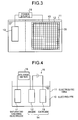
- a used adsorbent mentioned above may be used as an electrode by connecting an electric wire thereto.
- a used adsorbent 20 may be sandwiched by grid-form electrodes 12.
- the grid-form electrodes 12 are used, a potential can be applied uniformly to the entire adsorbent, thereby increasing a precipitation efficiency of mercury.
- FIG. 4 illustrates a processing apparatus for eluting an adsorbed substance by electrolysis according to Example 2.
- an electrode device 14 including an electrolytic cell 11 filled with an electrolyte 10, an anode 12 formed of a used adsorbent and soaked in the electrolyte 10, and a cathode 13 (the opposite electrode); a power source 15 for applying a voltage to the electrode device 14, and a saturated calomel electrode 17 serving as a reference electrode; and a voltage meter 16 for measuring the potential between the cathode 12 and the electrode 17.
- the electrode formed of a used adsorbent is employed as the anode 12
- platinum (Pt) is used as the cathode 13 which is the opposite electrode of the anode 12
- sodium chloride is used as the electrolyte 10.
- sodium chloride for example, potassium chloride or sodium carbonate may be used as the electrolyte 10.
- mercury is eluted in the electrolyte 10 as Hg ions (Hg 2 2+ ) through an oxidization-reduction reaction by applying a voltage from a power source 15 to the electrode device 14. Then, the voltage of the power source is varied to perform anode/cathode polarization sweeping (+1V to -1V).
- an alkaline agent such as sodium hydroxide (NaOH) or potassium hydroxide (KOH) is added in the electrolyte 10 to increase the molar ratio of Na or K to Hg.
- an oxidizing agent such as hydrogen peroxide (H 2 O 2 ) or ozone (O 3 ) is added to the electrolyte 10 to obtain mercurous oxide (HgO), which is allowed to precipitate and recovered.
- mercury can be selectively removed by applying a voltage from about 0.5V to 0.8V, and visa versa.
- Example 5 will be described next.
- electrolysis was performed by using the apparatus described in Example 1 and shown in Fig. 1.
- the electrode device 14 was constituted of a cathode 13 formed of a used adsorbent and an anode 12 (the opposite electrode) formed of platinum (Pt).
- the electrolyte sodium chloride was used.
- Mercury was adsorbed to the used adsorbent in advance.
- an adsorbed substance, mercury (Hg) was eluted as Hg ions (HgCl 4 2- ) in the electrolyte 10.
- potassium chloride or sodium carbonate other than sodium chloride may be mentioned.
- a regeneration method for an adsorbent a method for regenerating a used adsorbent by using it as an electrode in an electrolysis apparatus may be used as described above. Besides this, as shown in Fig. 8, a method for applying a voltage from a power source 15 by use of a wire which has been provided in the purification tower 104 serving as an exhaust gas treatment apparatus.
- the opposite electrode may be prepared in sulfuric acid 106 in advance.
- water or sulfuric acid
- the catalyst vessel 107 serving as an adsorbent to maintain a circuit at an electrically connected state for applying a voltage.
- the catalyst vessel 107 is taken out from the purification tower 104 serving as the exhaust-gas treatment apparatus and loaded by a transfer device 30 to regeneration treatment equipment 31 separately provided. After an adsorbed substance was removed, the catalyst vessel 107 may be returned to the purification tower 104 or the like and used again.
- the adsorbed substance thus removed is recovered and subjected to a final disposal process or recycled as a source.
- Fig. 15 is a schematic view of a waste treatment apparatus according to the embodiment having an aqueous thermal oxidation decomposition treatment apparatus and a sludge recovery unit.
- the waste treatment apparatus has an aqueous thermal oxidation decomposition apparatus 1002 for performing aqueous thermal oxidation decomposition of a slurry 1001 containing a waste (carbon material) to be treated in the presence of oxygen in supercritical state or sub-critical state; a sludge recovery unit 1004 that recovers a harmful metal or a valuable metal adsorbed to the waste to be treated as a sludge 1003; a dissolution unit 1006 that dissolves the recovered sludge 1003 in a nitric acid solution 1005; and a pressure/temperature control unit 1007 that controls the pressure and temperature of the dissolution unit 1006 to be high.
- a aqueous thermal oxidation decomposition apparatus 1002 for performing aqueous thermal oxidation decomposition of a slurry 1001 containing a waste (carbon material) to be treated in the presence of oxygen in supercritical state or sub-critical state
- a sludge recovery unit 1004 that recovers a harmful metal or a
- the pressure/temperature control unit 1007 includes a pressurizing unit 1007a that increases the pressure of the inner atmosphere of the dissolution unit 1006 to a value as high as 25 mega pascals or more which produces a supercritical state or sub-critical state; and a heating unit 1007b that heats the inner atmosphere of the dissolution unit 1006 to a temperature as high as 200°C or more.
- activated carbon fiber as activated carbon, as an example of waste to be treated.
- the activated carbon fiber is used in a desulfurization apparatus, it is formed into a sheet by use of an organic binder.
- the activated carbon fiber sheet is subjected to waste treatment, it is preferable that the sheet is cut into pieces, converted into slurry in order to improve the flowablity, and then subjected to aqueous thermal oxidation treatment.
- the aqueous thermal oxidation decomposition apparatus 1002 includes a cylindrical primary reaction tower 1101, pressurizing pumps 1105a to 1105d for independently pressurizing individual treatment solutions: carbon-material slurry 1001, oil (or organic solvent) 1102, sodium hydroxide (NaOH) 1103, and water (H 2 O 1104; a heat exchanger 1106 for preheating the water 1104; a secondary reaction tower 1107 having a spiral tube structure; a cooler 1108; and a reducing valve 1109. Furthermore, downstream of the reducing valve 1109, a gas-liquid separation apparatus 1110 and activated charcoal vessel 1111 are arranged. Exhaust gas (CO 2 ) 1112 is released outside from a chimney 1113 and discharge water (H 2 O, NaCl) 1114 is stored in a release tank 1115 and separately discharged as needed.
- CO 2 Exhaust gas
- an oxidizing agent 1116 such as oxygen (O 2 ) is supplied by high-pressure oxygen supply equipment 1117, and an oxygen supply pipe 1118 is directly connected to the primary reaction tower 1101.
- the oil (or an organic solvent ) 1102 is used particularly to accelerate a decomposition reaction and increase the reaction temperature to the optimal temperature at the start-up time of the decomposition apparatus 1002.
- the carbon material slurry 1001, sodium hydroxide 1103, and water 1104 may be mixed and supplied to the primary reaction tower 101 as a treatment liquid.
- the inner pressure of the primary reaction tower 1101 is increased to, for example, 26 mage pascals, by the pressuring pump 1105.
- the heat exchanger 1106 preheats water (H 2 O) to about 300°C.
- the oxygen 1116 is effused and increases its temperature to 380 to 400°C by the heat of the reaction taking place inside the tower.
- an organic substance has been decomposed into CO 2 to H 2 O.
- a fluid supplied from the secondary reaction tower 1107 is cooled to a temperature of about 100°C and reduced in pressure to atmospheric pressure by the reducing valve 1109 provided downstream.
- CO 2 , water vapor, and treatment liquid are separated by the gas-liquid separation apparatus 1110.
- the CO 2 and water vapor are exhausted into the environment through an activated charcoal layer 1111.
- the method for treating waste includes an aqueous thermal oxidation decomposition step of performing aqueous thermal oxidation decomposition of a waste material to be treated by using the above apparatus in the presence of oxygen in supercritical state or sub-critical state; a sludge recovering step of recovering an inorganic material adsorbed to the waste material as a sludge; a dissolution step of adding the sludge thus recovered in a nitric acid solution to dissolve it; and a metal removing step of removing a metal by gradually increasing a temperature of the metal under high pressure conditions to crystallize the metal at a crystallization temperature intrinsic to the metal, followed by precipitating the metal as a metal oxide.
- the activated charcoal, activated carbon fiber, and organic substance recovered are subjected to aqueous thermal oxidation decomposition performed in an aqueous solution such as an aqueous NaCO 3 solution in the supercritical state (or sub-critical state) while supplying oxygen.
- an aqueous solution such as an aqueous NaCO 3 solution in the supercritical state (or sub-critical state) while supplying oxygen.
- organic substances such as carbon matters and a binder are decomposed into completely harmless substances, CO 2 and water (H 2 O).
- inorganic substances such as metals adsorbed to activated charcoal cannot be decomposed by aqueous thermal oxidation decomposition. Therefore, after aeration of oxygen is stopped, they are allowed to precipitate on the bottom of the primary reaction tower 1101 as the sludge 1003, and transferred to the sludge recovery unit 1004 while maintaining its supercritical state or sub-critical state.
- the inorganic substances are returned once to a normal temperature and pressure by the sludge recovery unit 1004 and then added to dissolution unit 1006 containing a nitric acid solution 1005.
- the pressure of the dissolution unit 1006 is set at, for example, 30 mega pascals, by the pressure increasing unit 1007a and the temperature thereof is increased to 200°C by the heating unit 1007b.
- Mo and Zr are precipitated as oxides, which are transferred to a separated collection unit 1010 to recover as precipitates, separately.
- the nitric acid solution, from which the precipitate is removed, is returned again to the dissolution unit 1006 and heated to increase the temperature to 250°C by the heating unit 1007b.
- Fe is precipitated as an oxide, which is then transferred to the separated collection unit 1010 to recover a precipitate separately.
- the nitric acid solution, from which the precipitate is removed, is returned again to the dissolution unit 1006 and heated to increase the temperature to 275°C by the heating unit 1007b.
- Cr is precipitated as an oxide, which is then transferred to the separated collection unit 1010 to recover a precipitate separately.
- the nitric acid solution, from which the precipitate is removed, is returned again to the dissolution unit 1006 and heated to increase the temperature to 350°C by the heating unit 1007b.
- Pd is precipitated as an oxide, which is then transferred to the separated collection unit 1010 to recover a precipitate separately.
- organic substances can be decomposed into carbon dioxide and water by the aqueous thermal oxidation decomposition apparatus.
- inorganic substances (other than the organic substances) are not discarded as sludge. From the sludge, valuable metals are recovered and can be reused. This process differs from simple combustion, mercury is not discharged outside as it is.
- activated charcoal and activated carbon fiber are mentioned as wastes to be treated.
- the present invention is not limited to these.
- Use may be made of a wiping waste (used for wiping materials in electronic part printing step) having precious-metals such as Au, Ag, Pt, and Pd attached thereto, an RO film (used in a sea-water desalinization apparatus) having substances such as Co, Fe, Ca, and Mg attached thereto, ion exchange resin having a metal such as Au, Ag and Pd attached thereto, chelate resin having a substance such as U and Co attached thereto, and dust-collecting textile such as a bag filter.
- a method for treating waste includes an aqueous thermal oxidation decomposition step of performing aqueous thermal oxidation decomposition of a carbon material in the presence of oxygen in the supercritical state or sub-critical state and; a sludge recovering step of recovering a harmful metal or a valuable metal adsorbed to the waste; a first dissolution step of adding the sludge thus recovered in a nitric acid solution to dissolve it; a first metal removing step of removing metals such as Zr, Mo, Fe, Cr, and Pd as first precipitating metal oxides by increasing the temperature to 360°C under high pressure conditions of 30 mega pascals; a second dissolution step of adding the first precipitating metal oxide in a nitric acid solution to dissolve it; a second metal removing step of removing metals such as Zr, Mo, Fe, and Cr as second precipitating metal oxides by increasing the temperature to 280°C under high pressure conditions of 30 mega pascals; a third dissolution step of adding
- the sludge taken out from the primary reaction tower 1101 is recovered by the sludge recovering unit 1004 and added to a nitric acid solution in the dissolution unit 1006.
- the first dissolution step is performed.
- the temperature is increased to 360°C under high pressure conditions of 30 mage pascals to precipitate Zr, Mo, Fe, Cr and Pd as first precipitating metal oxides.
- the first precipitating metal oxides are then taken out and separated in the separated collection unit 1010 and again added to the nitric acid solution in the dissolution unit 1006. In this manner, the second dissolution step is performed. Then, the temperature is increased to 280°C under high pressure conditions of 30 mega pascals to precipitate Zr, Mo, Fe, and Cr as second precipitating metal oxides.
- the second precipitating metal oxides are taken out and separated in the separated collection unit 1010 and again added to the nitric acid solution in the dissolution unit 1006.
- the third dissolution step is performed.
- the temperature is increased to 240°C under high temperature conditions of 30 mega pascals to precipitate Zr and Mo as the third precipitating metal oxides.
- the aqueous solution from which the second precipitating metal oxides are removed is vaporized or increased to 360°C or more to precipitate Pd, thereby recovering Pd present in the nitric acid solution.
- the aqueous solution from which the third precipitating metal oxides are removed is vaporized or increased to 280°C or more to precipitate Fe and Cr, thereby recovering Fe and Cr present in the nitric acid solution.
- the method for the present invention includes an aqueous thermal oxidation decomposition step of performing aqueous thermal oxidation decomposition of a material to be treated (carbon material) in the presence of oxygen in a super critical state or sub-critical state; a sludge recovery step of recovering a harmful metal and a valuable metal adsorbed to the material to be treated as a sludge; a dissolution step of dissolving the sludge thus recovered in a nitric acid solution; and a metal removing step of gradually increasing the temperature under high pressure conditions to recrystallize metals, thereby removing metals as a metal oxide. Therefore, it is possible to recover valuable metals and maintain harmful metals such as Hg in the sludge without discharging them outside.
Landscapes
- Chemical & Material Sciences (AREA)
- Chemical Kinetics & Catalysis (AREA)
- Organic Chemistry (AREA)
- Analytical Chemistry (AREA)
- Electromagnetism (AREA)
- Materials Engineering (AREA)
- Physics & Mathematics (AREA)
- Health & Medical Sciences (AREA)
- Engineering & Computer Science (AREA)
- General Health & Medical Sciences (AREA)
- Toxicology (AREA)
- Treating Waste Gases (AREA)
- Water Treatment By Sorption (AREA)
- Solid-Sorbent Or Filter-Aiding Compositions (AREA)
- Processing Of Solid Wastes (AREA)
- Water Treatment By Electricity Or Magnetism (AREA)
- Electrolytic Production Of Non-Metals, Compounds, Apparatuses Therefor (AREA)
Applications Claiming Priority (4)
| Application Number | Priority Date | Filing Date | Title |
|---|---|---|---|
| JP2003092746 | 2003-03-28 | ||
| JP2003092746A JP4064850B2 (ja) | 2003-03-28 | 2003-03-28 | 廃棄物の処理方法及び処理装置 |
| JP2003198122A JP2005034705A (ja) | 2003-07-16 | 2003-07-16 | 吸着材の再生方法及び再生装置 |
| JP2003198122 | 2003-07-16 |
Publications (1)
| Publication Number | Publication Date |
|---|---|
| EP1468733A1 true EP1468733A1 (fr) | 2004-10-20 |
Family
ID=32911472
Family Applications (1)
| Application Number | Title | Priority Date | Filing Date |
|---|---|---|---|
| EP04006938A Ceased EP1468733A1 (fr) | 2003-03-28 | 2004-03-23 | Procédé et appareil pour régénérer un adsorbant |
Country Status (5)
| Country | Link |
|---|---|
| US (1) | US7267710B2 (fr) |
| EP (1) | EP1468733A1 (fr) |
| KR (1) | KR100651433B1 (fr) |
| CN (2) | CN101700493A (fr) |
| CA (1) | CA2462018C (fr) |
Cited By (1)
| Publication number | Priority date | Publication date | Assignee | Title |
|---|---|---|---|---|
| EP2714236A4 (fr) * | 2011-05-26 | 2015-07-08 | Biolargo Life Technologies Inc | Charbon actif associé à de l'iodure |
Families Citing this family (26)
| Publication number | Priority date | Publication date | Assignee | Title |
|---|---|---|---|---|
| GB0516154D0 (en) * | 2005-08-05 | 2005-09-14 | Ntnu Technology Transfer As | Carbon membranes |
| GB2438850B (en) * | 2006-04-28 | 2010-04-21 | Univ Manchester | Liquid treatment apparatus |
| DE102006036476A1 (de) * | 2006-08-04 | 2008-02-07 | Khs Ag | Filtereinsatz |
| US7803296B2 (en) * | 2007-06-11 | 2010-09-28 | United States Gypsum Company | Methods and systems for preparing gypsum slurry containing a cellulose ether |
| US20090101009A1 (en) * | 2007-10-23 | 2009-04-23 | United Technologies Corporation | Core separator integration for mercury removal from flue gases of coal-fired boilers |
| US20100050869A1 (en) * | 2008-08-28 | 2010-03-04 | Kishor Purushottam Gadkaree | Plate System For Contaminant Removal |
| JP2010158661A (ja) * | 2009-01-12 | 2010-07-22 | Ind Technol Res Inst | 低エネルギー消費の脱着装置とその除湿装置 |
| KR20110019968A (ko) * | 2009-08-21 | 2011-03-02 | 삼성전자주식회사 | 정수 필터 시스템과 그의 재생방법 및 정수 필터 시스템을 포함하는 정수 장치 |
| US20120187054A1 (en) * | 2011-01-21 | 2012-07-26 | Samsung Electronics Co., Ltd. | Regenerable filter device and method of driving the same |
| CN102690004B (zh) * | 2012-06-12 | 2013-09-04 | 爱思特水务科技有限公司 | 一种电吸附模块改性系统及工艺 |
| CN103432995B (zh) * | 2013-09-11 | 2016-01-20 | 北京中能环科技术发展有限公司 | 一种凝结水处理中活性炭纤维的再生方法 |
| WO2015181807A1 (fr) | 2014-05-30 | 2015-12-03 | Ozono Polaris, S.A. de C.V. | Aseptisation et régénération de milieu filtrant poreux à l'aide d'ozone par rétrolavage |
| US10052580B2 (en) * | 2016-12-28 | 2018-08-21 | Uop Llc | Trim bed for adsorption separation zone |
| CN107200327A (zh) * | 2017-04-19 | 2017-09-26 | 句容市百诚活性炭有限公司 | 一种再生活性炭制备方法 |
| US10906818B2 (en) | 2017-12-22 | 2021-02-02 | Ozono Polaris, S.A. de C.V. | Process for back-and-forth washing of adsorptive media |
| FR3078899B1 (fr) * | 2018-03-14 | 2021-03-05 | Univ Paris Est Marne La Vallee | Procede de regeneration du charbon actif par procede electro-fenton |
| CN111905884B (zh) * | 2018-08-28 | 2021-07-27 | 南京溧水高新产业股权投资有限公司 | 用于三年二十头三七脱帽加工的剪口脱帽清理机及方法 |
| CN109179405A (zh) * | 2018-09-27 | 2019-01-11 | 凯瑞环保科技股份有限公司 | 一种利用废离子交换树脂制备炭化树脂的方法 |
| CN112705009B (zh) * | 2019-10-25 | 2022-10-04 | 中冶长天国际工程有限责任公司 | 解析塔的冷却风机控制方法及装置 |
| CN113460998B (zh) * | 2021-06-24 | 2022-10-25 | 中国矿业大学 | 一种基于电容放电的高温热冲击材料连续化生产设备及方法 |
| CN113321210A (zh) * | 2021-06-24 | 2021-08-31 | 中国矿业大学 | 一种基于高温热冲击的废弃阴极炭快速修复方法与装置 |
| CN113321273A (zh) * | 2021-06-30 | 2021-08-31 | 潘玉琼 | 一种去除水中重金属的处理装置及其去除以及回收方法 |
| KR102572868B1 (ko) | 2022-09-20 | 2023-08-31 | 한국건설기술연구원 | 철성분이 함침된 활성탄의 제조 방법 및 이를 이용한 수중의 유기합성 화합물 제거 방법 |
| CN115739018B (zh) * | 2022-11-15 | 2024-09-27 | 中盐金坛盐化有限责任公司 | 一种熔盐法硫改性多孔材料的制备方法及其应用 |
| TWI814650B (zh) * | 2022-11-25 | 2023-09-01 | 住華科技股份有限公司 | 儲能系統及製程系統 |
| CN119488796A (zh) * | 2025-01-17 | 2025-02-21 | 山西辰润交通科技有限公司 | 一种沥青混凝土的沥青烟气净化处理设备 |
Citations (4)
| Publication number | Priority date | Publication date | Assignee | Title |
|---|---|---|---|---|
| US3730885A (en) * | 1971-01-21 | 1973-05-01 | Tvco Lab Inc | Electrochemical control of adsorption and desorption with activated carbon |
| US4217191A (en) * | 1972-10-12 | 1980-08-12 | Battelle Memorial Institute | Process for regenerating contaminated activated carbon |
| US4280886A (en) * | 1979-03-22 | 1981-07-28 | Hitachi, Ltd. | Method for treatment of sewage |
| US6391185B1 (en) * | 2000-01-05 | 2002-05-21 | Electrophor, Inc. | Composite regenerable adsorption carbon material and its regeneration method |
Family Cites Families (6)
| Publication number | Priority date | Publication date | Assignee | Title |
|---|---|---|---|---|
| CA2193638C (fr) | 1995-06-28 | 2000-01-25 | Isao Mochida | Systemes de traitement des gaz d'echappement |
| US5904832A (en) * | 1996-12-20 | 1999-05-18 | Huron Tech Canada, Inc. | Regeneration of active carbon and polymeric adsorbents |
| JP3659802B2 (ja) | 1998-06-09 | 2005-06-15 | 三菱重工業株式会社 | 排煙脱硫装置 |
| JP3459994B2 (ja) | 1998-12-03 | 2003-10-27 | 日立造船株式会社 | 排ガス中の有害物質除去用吸着剤の再生方法およびその装置 |
| JP3342438B2 (ja) | 1999-05-20 | 2002-11-11 | 三菱重工業株式会社 | Pcb含有電気絶縁油の処理方法およびその処理装置 |
| GB2365023B (en) * | 2000-07-18 | 2002-08-21 | Ionex Ltd | A process for improving an electrode |
-
2004
- 2004-03-15 US US10/799,781 patent/US7267710B2/en not_active Expired - Fee Related
- 2004-03-23 EP EP04006938A patent/EP1468733A1/fr not_active Ceased
- 2004-03-24 CN CN200910226432A patent/CN101700493A/zh active Pending
- 2004-03-24 CN CN200410008579A patent/CN100591414C/zh not_active Expired - Fee Related
- 2004-03-26 KR KR1020040020618A patent/KR100651433B1/ko not_active Expired - Fee Related
- 2004-03-26 CA CA002462018A patent/CA2462018C/fr not_active Expired - Fee Related
Patent Citations (4)
| Publication number | Priority date | Publication date | Assignee | Title |
|---|---|---|---|---|
| US3730885A (en) * | 1971-01-21 | 1973-05-01 | Tvco Lab Inc | Electrochemical control of adsorption and desorption with activated carbon |
| US4217191A (en) * | 1972-10-12 | 1980-08-12 | Battelle Memorial Institute | Process for regenerating contaminated activated carbon |
| US4280886A (en) * | 1979-03-22 | 1981-07-28 | Hitachi, Ltd. | Method for treatment of sewage |
| US6391185B1 (en) * | 2000-01-05 | 2002-05-21 | Electrophor, Inc. | Composite regenerable adsorption carbon material and its regeneration method |
Cited By (1)
| Publication number | Priority date | Publication date | Assignee | Title |
|---|---|---|---|---|
| EP2714236A4 (fr) * | 2011-05-26 | 2015-07-08 | Biolargo Life Technologies Inc | Charbon actif associé à de l'iodure |
Also Published As
| Publication number | Publication date |
|---|---|
| CA2462018C (fr) | 2008-05-13 |
| KR100651433B1 (ko) | 2006-11-29 |
| KR20040084997A (ko) | 2004-10-07 |
| CA2462018A1 (fr) | 2004-09-28 |
| US20040187685A1 (en) | 2004-09-30 |
| CN1533834A (zh) | 2004-10-06 |
| CN100591414C (zh) | 2010-02-24 |
| US7267710B2 (en) | 2007-09-11 |
| CN101700493A (zh) | 2010-05-05 |
Similar Documents
| Publication | Publication Date | Title |
|---|---|---|
| US7267710B2 (en) | Method of and apparatus for regenerating adsorbent | |
| JP3518112B2 (ja) | 燃料電池の水処理装置 | |
| EP0405619B1 (fr) | Procédé et appareil de traitement d'un effluent contenant du chlore | |
| KR101767894B1 (ko) | 질소 순환형 질소산화물 처리 시스템 및 방법 | |
| JP2004174370A (ja) | ガス処理方法とその装置及びシステム | |
| CN109433006A (zh) | 一种烟气处理工艺流程及其装备配置 | |
| JP2004344834A (ja) | 硫黄酸化物を含有するガスの脱硫方法、脱硫装置、灰分の処理方法、硫黄酸化物含有溶液の処理方法 | |
| JP2004174369A (ja) | ガス処理方法とそのシステム | |
| JP2005034705A (ja) | 吸着材の再生方法及び再生装置 | |
| KR100557790B1 (ko) | 배가스 중 이산화탄소의 제거 방법 | |
| CN114133072A (zh) | 一种含二氧化碳捕集吸收剂的废液的处理系统及方法 | |
| Bolger et al. | An electrochemical system for removing and recovering elemental mercury from a gas stream | |
| JP2003236334A (ja) | 排煙処理液浄化システム | |
| JP2005038823A (ja) | 固体高分子型燃料電池システム | |
| WO2005089906A1 (fr) | Appareil de concentration de gaz méthane | |
| JP2002284510A (ja) | 排ガス処理システムの硫酸回収方法及び硫酸回収装置 | |
| JP2004174371A (ja) | ガス処理方法とそのシステム | |
| KR102739290B1 (ko) | 수처리시스템 | |
| WO2015177999A1 (fr) | Procédé de traitement de gaz contenant du mercure de valence zéro, et procédé de séparation du mercure | |
| CN116768430B (zh) | 一种碱性电解液的处理方法及系统 | |
| JP4615257B2 (ja) | 燃料電池用ガス浄化器 | |
| CN118005149B (zh) | BiOBr活性炭FCDI耦合流动阴极-溴回收的系统及Br-的回收方法 | |
| JP2004327429A (ja) | 燃料電池および燃料電池用空気浄化装置 | |
| CN223357471U (zh) | 一种含有机硫废液的处理系统 | |
| JP5228575B2 (ja) | 燃料電池発電装置 |
Legal Events
| Date | Code | Title | Description |
|---|---|---|---|
| PUAI | Public reference made under article 153(3) epc to a published international application that has entered the european phase |
Free format text: ORIGINAL CODE: 0009012 |
|
| 17P | Request for examination filed |
Effective date: 20040323 |
|
| AK | Designated contracting states |
Kind code of ref document: A1 Designated state(s): AT BE BG CH CY CZ DE DK EE ES FI FR GB GR HU IE IT LI LU MC NL PL PT RO SE SI SK TR |
|
| AX | Request for extension of the european patent |
Extension state: AL LT LV MK |
|
| AKX | Designation fees paid |
Designated state(s): AT BE BG CH CY CZ DE DK EE ES FI FR GB GR HU IE IT LI LU MC NL PL PT RO SE SI SK TR |
|
| STAA | Information on the status of an ep patent application or granted ep patent |
Free format text: STATUS: THE APPLICATION HAS BEEN REFUSED |
|
| 18R | Application refused |
Effective date: 20121009 |