EP1468784A2 - Tête de meulage pour une machine à meuler les feuilles de verre et machine équipée d'une telle tête de meulage - Google Patents
Tête de meulage pour une machine à meuler les feuilles de verre et machine équipée d'une telle tête de meulage Download PDFInfo
- Publication number
- EP1468784A2 EP1468784A2 EP04007351A EP04007351A EP1468784A2 EP 1468784 A2 EP1468784 A2 EP 1468784A2 EP 04007351 A EP04007351 A EP 04007351A EP 04007351 A EP04007351 A EP 04007351A EP 1468784 A2 EP1468784 A2 EP 1468784A2
- Authority
- EP
- European Patent Office
- Prior art keywords
- grinding
- head
- slabs
- supporting structure
- spindles
- Prior art date
- Legal status (The legal status is an assumption and is not a legal conclusion. Google has not performed a legal analysis and makes no representation as to the accuracy of the status listed.)
- Granted
Links
Images


Classifications
-
- B—PERFORMING OPERATIONS; TRANSPORTING
- B24—GRINDING; POLISHING
- B24B—MACHINES, DEVICES, OR PROCESSES FOR GRINDING OR POLISHING; DRESSING OR CONDITIONING OF ABRADING SURFACES; FEEDING OF GRINDING, POLISHING, OR LAPPING AGENTS
- B24B9/00—Machines or devices designed for grinding edges or bevels on work or for removing burrs; Accessories therefor
- B24B9/02—Machines or devices designed for grinding edges or bevels on work or for removing burrs; Accessories therefor characterised by a special design with respect to properties of materials specific to articles to be ground
- B24B9/06—Machines or devices designed for grinding edges or bevels on work or for removing burrs; Accessories therefor characterised by a special design with respect to properties of materials specific to articles to be ground of non-metallic inorganic material, e.g. stone, ceramics, porcelain
- B24B9/08—Machines or devices designed for grinding edges or bevels on work or for removing burrs; Accessories therefor characterised by a special design with respect to properties of materials specific to articles to be ground of non-metallic inorganic material, e.g. stone, ceramics, porcelain of glass
- B24B9/10—Machines or devices designed for grinding edges or bevels on work or for removing burrs; Accessories therefor characterised by a special design with respect to properties of materials specific to articles to be ground of non-metallic inorganic material, e.g. stone, ceramics, porcelain of glass of plate glass
- B24B9/102—Machines or devices designed for grinding edges or bevels on work or for removing burrs; Accessories therefor characterised by a special design with respect to properties of materials specific to articles to be ground of non-metallic inorganic material, e.g. stone, ceramics, porcelain of glass of plate glass for travelling sheets
-
- B—PERFORMING OPERATIONS; TRANSPORTING
- B24—GRINDING; POLISHING
- B24B—MACHINES, DEVICES, OR PROCESSES FOR GRINDING OR POLISHING; DRESSING OR CONDITIONING OF ABRADING SURFACES; FEEDING OF GRINDING, POLISHING, OR LAPPING AGENTS
- B24B41/00—Component parts such as frames, beds, carriages, headstocks
- B24B41/04—Headstocks; Working-spindles; Features relating thereto
Definitions
- the present invention refers to a grinding head for a grinding machine for glass slabs, and to a grinding machine for glass slabs equipped with such grinding head.
- the grinding plants being used comprise a conveyor adapted to advance the glass slabs along an horizontal path through two working stations, each one of which houses a plurality of grinding wheels arranged in fixed positions along the path itself in order to grind two mutually opposite sides of the perimeter edge when advancing each slab.
- Object of the present invention is realising a grinding head for a grinding machine for glass slabs, which allows easily and economically solving the above-mentioned problem and, in particular, allows accurately working each glass slab in a working station where the slab itself is kept in a fixed univocal reference position when working the related edge.
- a further object of the present invention is realising a grinding head of the above-mentioned type that is adapted to simultaneously work the glass slabs on two perpendicular sides, through workings that are mutually different and are also operating at different speeds.
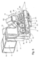
- Such grinding head 77 is adapted to be placed on a grinding machine 1 for glass slabs 2 (Fig. 4) and substantially comprises:
- the grinding wheels 20, 28 for grinding and laterally polishing rotate, independently one from another (through respective motors that actuate the various spindles 10, 14, 16, 18), around an axis that is perpendicular to the rotation axis of the grinding wheels 24, 26 for grinding and polishing the threads.
- the grinding wheels 20, 22, 24, 26, 28 for grinding and laterally polishing and polishing the threads are adapted to perform, when working, an axial movement along the slabs 2, in which the axial movements of the grinding wheels 20, 22, 24, 26, 28 are able to be independently actuated one from another.
- the grinding wheels for laterally grinding are two 20, 22 and are rotatingly driven by two respective spindles 10, 12.
- the grinding wheels 20, 22, 24, 26, 28 are further driven in their axial advancement by respective motors 21, 23, 25, 27, 29 for obtaining a maximum working flexibility.
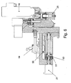
- the spindles 16, 18 are each equipped with resilient means 51 (commonly a spring) pre-loaded by a stepped motor 27 and that drive a ball screw 53 (pushed by the spring 51) for realising such constant pressure on the glass slabs 2 when working.
- resilient means 51 commonly a spring
- ball screw 53 pushed by the spring 51
- the spindles 16, 18 are equipped each with braking means 54 that operate on sliding guides 55 and block the advancement of the grinding wheels 26, 28 against the glass slabs 2 between one slab 2 and the following slab 2, in order to avoid that the grinding wheels 26, 28 penetrate into the hollow space between two successive glass slabs 2 when working; the braking means 54 instead unlock the grinding wheels 26, 28 when they have to work on a glass slab 2 in a working position.
- the supporting structure 9 is further equipped with supporting means 30 for the glass slabs 2, in which the supporting means 30 are equipped with a plurality of small wheels 31 that make sliding of the slabs 2 easier.
- Control means 32 are further visible, that are contained (and joined through rear closing means 38) in the part of the structure 9 that is opposed to the one in which there are the grinding wheels 20, 22, 24, 26, 28.
- the thereby shown grinding wheel 77 allows performing, on a fixed glass slab 2, a plurality of grinding and polishing operations, driving the grinding wheels and the respective spindles at mutually different speeds and placing the grinding wheels next to different parts of the slab 2 on which it is necessary to perform the relevant workings.
- reference 1 globally shows a grinding machine for glass slabs, one of which (partially shown) is designated with 2, and comprises a related perimeter edge 5 to be ground that has, in particular, a plane rectangular shape.
- the machine 1 comprises a basement 8 (partially shown), which carries a conveyor assembly 9 (partially shown) comprising, in particular, a plurality of dragging bands 10 to transfer the slab 2 on an horizontal plane 11 along a rectilinear horizontal longitudinal direction A starting from a loading station towards an unloading station through a working station 14.
- the station 14 houses a positioning assembly (not shown) for arranging the slab 2 to be worked in a reference position on plane 11, and a retention assembly 44 (schematically shown), in particular a pneumatic assembly with suction cups, in order to keep the slab 2 itself in such reference position when grinding.
- a positioning assembly (not shown) for arranging the slab 2 to be worked in a reference position on plane 11, and a retention assembly 44 (schematically shown), in particular a pneumatic assembly with suction cups, in order to keep the slab 2 itself in such reference position when grinding.
- the machine 1 further comprises a chassis 56 (partially shown), in particular a portal chassis, fixed with respect to the basement 8 and comprising a stringer 59, which is longitudinally extended along station 14, has a related guide 73 parallel to direction A and supports the grinding head 77 adapted to grind a side 78 of the edge 5 parallel to direction A.
- a chassis 56 (partially shown), in particular a portal chassis, fixed with respect to the basement 8 and comprising a stringer 59, which is longitudinally extended along station 14, has a related guide 73 parallel to direction A and supports the grinding head 77 adapted to grind a side 78 of the edge 5 parallel to direction A.
- the head 77 comprises a fork-shaped structure 80 in turn comprising two mutually facing and parallel arms 81, and an intermediate cross member 82 connecting the arms 81 themselves, that is movably coupled to the stringer 59 through an assembly 84 for attaching and handling the structure 80.
- the assembly 84 is part of the head 77 and comprises a trolley 85 slidingly coupled to the guide 73 for advancing the structure 80 along the side 78, and a fifth wheel 86 interposed between the trolley 85 and the cross member 82 and adapted to allow a structure 80 rotation with respect to the trolley 85 around a vertical axis 87 that is orthogonal to the guide 73.
- the trolley 85 and the fifth wheel 86 are actuated, by interposing a transmission, not shown, and housed in the stringer 59, from a motor assembly 88 supported, in particular, by the chassis 56 and driven by a driving and control unit 25' (schematically shown) of the machine 1.
- the structure 80 supports a plate 89, which is interposed between the arms 81, is integrally connected to the free ends of the arms 81 themselves, and comprises a portion 90 that supports, in turn, four spindles 91, 92, 93, 94 that are mutually placed side by side along a horizontal rectilinear direction B, orthogonal to the arms 81 and parallel to side 78 when grinding.
- the spindles 91, 92, 93, 94 are able to rotate around respective axes 96, 97, 98, 99 orthogonal to direction B and projectingly carry respective ring-shaped grinding wheels 101, 102, 103, 104, which are integral and coaxial with the related spindles 91, 92, 93, 94, have respective annular axial grinding surfaces facing the side 78, and are housed in a not-shown guard.
- the axes 96, 97 are mutually parallel and lie on a plane parallel to slab 2, while axes 98, 99 are mutually skewed and form respective angles that are mutually equal and opposite with the plane in which axes 96, 97 lie, so that each grinding wheel 103, 104 can bevel a related edge of side 78.
- the grinding wheels 101, 102, 103, 104 are arranged in such position and have such sizes as to globally show an encumbrance L, measured in parallel with direction B, included between 25 and 35 centimeters and preferably equal to 30 centimeters.
- the head 77 comprises, for each spindle 91, 92, 93, 94, a related motor 111, 112, 113, 114 coupled the spindle 91, 92, 93, 94 itself by interposing a transmission (not shown), preferably a belt transmission, in order to rotate each grinding wheel 101, 102, 103, 104 around its related axis 96, 97, 98, 99 independently one from another.
- a transmission not shown
- the head 77 further comprises, for each spindle 91, 92, 93, 94, a related motor 121, 122, 123, 124 coupled with the spindle 91, 92, 93, 94 itself by interposing a related transmission (not shown), preferably a toothed wheel transmission, in order to axially place each grinding wheel 101, 102, 103, 104 with respect to the side 78 independently one from another.
- a related transmission not shown
- the motors 111, 112, 113, 114, 121, 122, 123, 124 are integrally connected with the plate 89, extend in intermediate positions between the arms 81, and preferably have respective elongated structures in orthogonal directions to direction B, in order to contain the encumbrance along direction B between the arms 81.
- the motors 121, 122 (partially visible in Fig. 5) and 124 are arranged on the opposite side of the related spindles 91, 92, 94 with respect to the cross member 82, while the motors 111, 112, 123, 113, 114 extend in parallel with the related axes 96, 97, 98, 99, in intermediate positions between portion 90 and cross member 82.
- the motors 111 and 112 projectingly extend from one portion 130 of the plate 89 in mutually aligned positions.
- the plate 2 is placed and blocked in the reference position in station 14.
- the motor assembly 88 is driven by the unit 25' in order to take the head 77 in a working start position corresponding to a first vertex of the side 78.
- the unit 25' drives the motors 121, 122, 123, 124 in order to axially approach the grinding wheels 101, 102, 103, 104 to the slab 2 and, finally, the assembly 88 and the motors 111, 112, 113, 114 in order to move the head 77 along an advancement path defined by the guide 73 and grind the side 78, till the second vertex of the side 78 itself is reached.
- the grinding wheels 101, 102, 103, 104 are axially backed, the head 77 is taken tack to the working starting point and the slab 2 is moved away from the station 14, in order to allow grinding a following glass slab.
- the head 77 allows grinding the edge 5 of a slab 2 kept in a fixed and univocal reference position by the assembly 44 and, therefore, realising a machine in which the positioning errors are reduced with respect to known arrangements, in which, instead, the slab 2 is passed through a working station where the grinding wheels are arranged in fixed positions. Therefore, the head 77 and the machine 11 guarantee a high quality index with respect to known arrangements and that is substantially unchanged from one slab 2 to another.
- the head 77 is extremely compact due to the arrangement of spindles 91, 92, 93, 94 and the elongated shape of the engines, and has a relatively small encumbrance measured between the arms 81, so that it is possible to also grind slabs 2 having relatively small sizes.
- the spindles 91, 92, 93, 94 are actuated by axially advancing motors 121, 122, 123, 124 and rotating motors 111, 112, 113, 114 that are mutually independent, and, therefore it is possible to accurately adjust both the axial positioning and the cutting parameters of each one of the grinding wheels 101, 102, 103, 104.
- the fifth wheel 86 allows departing the grinding wheels 101, 102, 103, 104 from the station 14 by rotating the structure 80 in order to easily perform the maintenance and replacement operations of the grinding wheels themselves.
- spindles and motors could be in a different number from the mentioned one and/or arranged in different positions from the shown ones.
- the machine 1 could comprise a plurality of heads 77, each one adapted to grind a related size of the glass slab 2.
Landscapes
- Engineering & Computer Science (AREA)
- Mechanical Engineering (AREA)
- Chemical & Material Sciences (AREA)
- Ceramic Engineering (AREA)
- Inorganic Chemistry (AREA)
- Grinding And Polishing Of Tertiary Curved Surfaces And Surfaces With Complex Shapes (AREA)
- Grinding Of Cylindrical And Plane Surfaces (AREA)
- Polishing Bodies And Polishing Tools (AREA)
- Finish Polishing, Edge Sharpening, And Grinding By Specific Grinding Devices (AREA)
- Constituent Portions Of Griding Lathes, Driving, Sensing And Control (AREA)
Applications Claiming Priority (2)
| Application Number | Priority Date | Filing Date | Title |
|---|---|---|---|
| ITTO20030297 | 2003-04-16 | ||
| IT000297A ITTO20030297A1 (it) | 2003-04-16 | 2003-04-16 | Testa di molatura per una macchina di molatura di |
Publications (3)
| Publication Number | Publication Date |
|---|---|
| EP1468784A2 true EP1468784A2 (fr) | 2004-10-20 |
| EP1468784A3 EP1468784A3 (fr) | 2005-05-11 |
| EP1468784B1 EP1468784B1 (fr) | 2009-09-16 |
Family
ID=32894200
Family Applications (1)
| Application Number | Title | Priority Date | Filing Date |
|---|---|---|---|
| EP04007351A Expired - Lifetime EP1468784B1 (fr) | 2003-04-16 | 2004-03-26 | Tête de meulage pour une machine à meuler les feuilles de verre et machine équipée d'une telle tête de meulage |
Country Status (5)
| Country | Link |
|---|---|
| US (1) | US7134936B2 (fr) |
| EP (1) | EP1468784B1 (fr) |
| AT (1) | ATE442938T1 (fr) |
| DE (1) | DE602004023148D1 (fr) |
| IT (1) | ITTO20030297A1 (fr) |
Cited By (6)
| Publication number | Priority date | Publication date | Assignee | Title |
|---|---|---|---|---|
| EP1649975A1 (fr) * | 2004-10-21 | 2006-04-26 | BIESSE S.p.A. | Dispositif pour obtenir des biseaux avec des pentes variables sur le bord du verre, le marbre, les galettes en pierre ou en céramique et des matériaux similaires. |
| WO2009034588A1 (fr) * | 2007-09-13 | 2009-03-19 | Forvet S.R.L. | Ensemble de doucissage pour plaques de verre et tête de doucissage pour machine de doucissage rectiligne équipée d'un tel ensemble |
| ITTO20120050A1 (it) * | 2012-01-23 | 2013-07-24 | Bottero Spa | Metodo per la molatura di lastre di vetro |
| CN104802072A (zh) * | 2015-04-13 | 2015-07-29 | 广东科达洁能股份有限公司 | 高速抛光磨头装置 |
| CN108907943A (zh) * | 2018-07-26 | 2018-11-30 | 望江县天长光学科技有限公司 | 一种光学镜片修边的磨头 |
| EP3581331A1 (fr) | 2018-06-13 | 2019-12-18 | Phup Remszklo s.c. | Ensemble de disques de meulage des bords de plaques de verre |
Families Citing this family (13)
| Publication number | Priority date | Publication date | Assignee | Title |
|---|---|---|---|---|
| ITTO20030297A1 (it) * | 2003-04-16 | 2004-10-17 | Forvet Srl | Testa di molatura per una macchina di molatura di |
| US7294045B1 (en) | 2005-12-21 | 2007-11-13 | Corning Incorporated | Apparatus and method for edge processing of a glass sheet |
| TW201036760A (en) * | 2009-03-19 | 2010-10-16 | Siemag Gmbh | Method and device for grinding a continuous casting product |
| US9555516B2 (en) * | 2009-07-24 | 2017-01-31 | Corning Incorporated | Method for processing an edge of a glass plate |
| DE102010025250A1 (de) * | 2009-08-18 | 2011-02-24 | Sms Logistiksysteme Gmbh | Verfahren und Vorrichtung zum Handhaben von Brammen zum Schleifen der Brammen-Oberflächen |
| CN102658513B (zh) * | 2012-06-05 | 2014-06-11 | 张东平 | 平底钻磨抛一体机 |
| CN204108775U (zh) * | 2014-06-10 | 2015-01-21 | 金华冠华水晶有限公司 | 一种全自动水钻磨抛机 |
| KR101804871B1 (ko) * | 2015-12-14 | 2017-12-05 | 한국푸마 주식회사 | 금속 판재용 삼면 면취 가공장치 |
| US11768475B2 (en) * | 2016-03-11 | 2023-09-26 | Forvet S.P.A. Costruzione Macchine Speciali | Machine for working glass slabs with a computerized numeric control assembly and related production process |
| IT201600079005A1 (it) * | 2016-07-27 | 2018-01-27 | Elettromeccanica Bovone Srl | Apparato modulare e metodo per la lavorazione di lastre piane |
| CN106891250B (zh) * | 2017-04-13 | 2023-11-07 | 广东高力威机械科技有限公司 | 卧式玻璃磨边的磨轮传动结构 |
| CN107695825B (zh) * | 2017-11-08 | 2023-08-25 | 佛山市南海东泰创展精密机械有限公司 | 一种玻璃磨边机及其工作方法 |
| CN113732865B (zh) * | 2021-08-06 | 2022-08-02 | 晟光科技股份有限公司 | 一种lcd显示屏玻璃外屏生产处理装置 |
Family Cites Families (16)
| Publication number | Priority date | Publication date | Assignee | Title |
|---|---|---|---|---|
| DE2009778A1 (de) * | 1970-03-03 | 1971-09-16 | Rautenstrauch, Martin, 4816 Senne Stadt | Schleif und Poliermaschine |
| JPS5493288A (en) * | 1977-12-31 | 1979-07-24 | Bando Kiko Co | Glass chamfering machine |
| US4228617A (en) * | 1977-12-31 | 1980-10-21 | Bando Kiko Co., Ltd | Method for grinding glass plates and the like through numerical control and beveling machine therefor |
| US4437268A (en) * | 1980-07-09 | 1984-03-20 | Hoyne Industries, Inc. | Beveling apparatus |
| CH653941A5 (de) * | 1980-12-13 | 1986-01-31 | Hauni Werke Koerber & Co Kg | Vorrichtung zum umspannen planparalleler werkstuecke. |
| DE3534425A1 (de) * | 1985-02-13 | 1986-08-14 | Benteler-Werke Ag Werk Neuhaus, 4790 Paderborn | Kantenschleifmaschine |
| IT1266734B1 (it) * | 1994-06-28 | 1997-01-14 | F M F Ind S R L | Gruppo per la molatura di lastre di vetro. |
| US5816897A (en) * | 1996-09-16 | 1998-10-06 | Corning Incorporated | Method and apparatus for edge finishing glass |
| IT1292686B1 (it) * | 1997-03-11 | 1999-02-11 | Pragma S R L | Metodo per la calibratura di elementi in pietra naturale o artificiale particolarmente piastrelle ceramiche, e macchina relativa. |
| AT408856B (de) * | 1997-12-02 | 2002-03-25 | Lisec Peter | Vorrichtung zum automatischen säumen von plattenförmigen gegenständen |
| US6325704B1 (en) * | 1999-06-14 | 2001-12-04 | Corning Incorporated | Method for finishing edges of glass sheets |
| ITMI991382A1 (it) * | 1999-06-21 | 2000-12-21 | Bavelloni Z Spa | Macchina automatica bilaterale per la lavorazione dei bordi di lastredi vetro materiali lapidei e simili |
| US6629875B2 (en) * | 2000-01-28 | 2003-10-07 | Accretech Usa, Inc. | Machine for grinding-polishing of a water edge |
| IT1315616B1 (it) * | 2000-03-15 | 2003-03-14 | Luigi Pedrini | Levigatrice per materiali lapidei, dotata di teste multiple allineatesu due travi oscillanti e parallele, nonche' con distanza regolabile. |
| IT1320847B1 (it) * | 2000-11-28 | 2003-12-10 | Bottero Spa | Metodo e macchina per la molatura di lastre di vetro rivestite. |
| ITTO20030297A1 (it) * | 2003-04-16 | 2004-10-17 | Forvet Srl | Testa di molatura per una macchina di molatura di |
-
2003
- 2003-04-16 IT IT000297A patent/ITTO20030297A1/it unknown
-
2004
- 2004-03-26 EP EP04007351A patent/EP1468784B1/fr not_active Expired - Lifetime
- 2004-03-26 DE DE602004023148T patent/DE602004023148D1/de not_active Expired - Lifetime
- 2004-03-26 AT AT04007351T patent/ATE442938T1/de active
- 2004-04-06 US US10/820,201 patent/US7134936B2/en not_active Expired - Lifetime
Cited By (8)
| Publication number | Priority date | Publication date | Assignee | Title |
|---|---|---|---|---|
| EP1649975A1 (fr) * | 2004-10-21 | 2006-04-26 | BIESSE S.p.A. | Dispositif pour obtenir des biseaux avec des pentes variables sur le bord du verre, le marbre, les galettes en pierre ou en céramique et des matériaux similaires. |
| WO2009034588A1 (fr) * | 2007-09-13 | 2009-03-19 | Forvet S.R.L. | Ensemble de doucissage pour plaques de verre et tête de doucissage pour machine de doucissage rectiligne équipée d'un tel ensemble |
| US8317571B2 (en) | 2007-09-13 | 2012-11-27 | Forvet S.R.L. | Grinding assembly for glass slabs and grinding head for a rectilinear grinding machine equipped with such assembly |
| ITTO20120050A1 (it) * | 2012-01-23 | 2013-07-24 | Bottero Spa | Metodo per la molatura di lastre di vetro |
| WO2013111069A1 (fr) * | 2012-01-23 | 2013-08-01 | Bottero S.P.A. | Procédé de meulage de plaques de verre |
| CN104802072A (zh) * | 2015-04-13 | 2015-07-29 | 广东科达洁能股份有限公司 | 高速抛光磨头装置 |
| EP3581331A1 (fr) | 2018-06-13 | 2019-12-18 | Phup Remszklo s.c. | Ensemble de disques de meulage des bords de plaques de verre |
| CN108907943A (zh) * | 2018-07-26 | 2018-11-30 | 望江县天长光学科技有限公司 | 一种光学镜片修边的磨头 |
Also Published As
| Publication number | Publication date |
|---|---|
| EP1468784B1 (fr) | 2009-09-16 |
| ATE442938T1 (de) | 2009-10-15 |
| ITTO20030297A1 (it) | 2004-10-17 |
| EP1468784A3 (fr) | 2005-05-11 |
| DE602004023148D1 (de) | 2009-10-29 |
| US7134936B2 (en) | 2006-11-14 |
| US20040209557A1 (en) | 2004-10-21 |
Similar Documents
| Publication | Publication Date | Title |
|---|---|---|
| EP1468784B1 (fr) | Tête de meulage pour une machine à meuler les feuilles de verre et machine équipée d'une telle tête de meulage | |
| US10328607B2 (en) | Machine for cutting stone material | |
| US6557689B2 (en) | Assembly for supporting and retaining glass sheets | |
| EP2998088B1 (fr) | Centre d'usinage pour dalles en pierre, marbre, matériau synthétique ou similaire avec plan de travail sacrificiel | |
| EP2983879B1 (fr) | Machine-outil multi-axiale pour le travail de dalles et/ou blocks de pierres | |
| EP3342535B1 (fr) | Dispositif de traitement de plaque de verre | |
| EP4363145B1 (fr) | Machine et installation pour l'usinage de dalles | |
| KR101469654B1 (ko) | 유리판의 가공 방법 및 유리판의 가공 장치 | |
| KR101206367B1 (ko) | 윈도우 글래스 연마장치 | |
| CN103659508A (zh) | 数控异型石材加工中心 | |
| EP1142671A1 (fr) | Meuleuse à colonne double | |
| EP2197628B1 (fr) | Tete de doucissage pour machine de doucissage pour plaques de verre | |
| JPH10291149A (ja) | ガラス板の角部研削装置 | |
| JP5154880B2 (ja) | ドレス装置を備えた硬質脆性板の面取装置 | |
| EP3632614B1 (fr) | Rectifieuse rectiligne | |
| EP0666140B1 (fr) | Procédé et dispositif pour usiner in secteur d'aubes | |
| CN219987150U (zh) | 工件打磨装置 | |
| CN202278468U (zh) | 水晶坯件自动磨抛系统 | |
| EP0724501A1 (fr) | Perfectionnements apportes aux meuleuses rectifieuses ou s'y rapportant | |
| CN212145828U (zh) | 一种海绵粉扑打磨设备及系统 | |
| EP3215329B1 (fr) | Machine pour couper du matériau en pierre | |
| EP0197233B1 (fr) | Machine pour travailler les bords sous forme d'arc de cercle des plaques de marbre, de granit et de matériaux analogues | |
| US20240424634A1 (en) | Tire-buffing system constituted by a robotized arm with angular interpolation movements | |
| CN202428285U (zh) | 一种磨水晶球的设备 | |
| US20250041945A1 (en) | Machine tool for machining workpieces and methods of operation thereof |
Legal Events
| Date | Code | Title | Description |
|---|---|---|---|
| PUAI | Public reference made under article 153(3) epc to a published international application that has entered the european phase |
Free format text: ORIGINAL CODE: 0009012 |
|
| AK | Designated contracting states |
Kind code of ref document: A2 Designated state(s): AT BE BG CH CY CZ DE DK EE ES FI FR GB GR HU IE IT LI LU MC NL PL PT RO SE SI SK TR |
|
| AX | Request for extension of the european patent |
Extension state: AL LT LV MK |
|
| PUAL | Search report despatched |
Free format text: ORIGINAL CODE: 0009013 |
|
| AK | Designated contracting states |
Kind code of ref document: A3 Designated state(s): AT BE BG CH CY CZ DE DK EE ES FI FR GB GR HU IE IT LI LU MC NL PL PT RO SE SI SK TR |
|
| AX | Request for extension of the european patent |
Extension state: AL LT LV MK |
|
| 17P | Request for examination filed |
Effective date: 20051011 |
|
| AKX | Designation fees paid |
Designated state(s): AT BE BG CH CY CZ DE DK EE ES FI FR GB GR HU IE IT LI LU MC NL PL PT RO SE SI SK TR |
|
| 17Q | First examination report despatched |
Effective date: 20090323 |
|
| GRAP | Despatch of communication of intention to grant a patent |
Free format text: ORIGINAL CODE: EPIDOSNIGR1 |
|
| GRAS | Grant fee paid |
Free format text: ORIGINAL CODE: EPIDOSNIGR3 |
|
| GRAA | (expected) grant |
Free format text: ORIGINAL CODE: 0009210 |
|
| AK | Designated contracting states |
Kind code of ref document: B1 Designated state(s): AT BE BG CH CY CZ DE DK EE ES FI FR GB GR HU IE IT LI LU MC NL PL PT RO SE SI SK TR |
|
| REG | Reference to a national code |
Ref country code: GB Ref legal event code: FG4D |
|
| REG | Reference to a national code |
Ref country code: CH Ref legal event code: EP |
|
| REG | Reference to a national code |
Ref country code: IE Ref legal event code: FG4D |
|
| REF | Corresponds to: |
Ref document number: 602004023148 Country of ref document: DE Date of ref document: 20091029 Kind code of ref document: P |
|
| REG | Reference to a national code |
Ref country code: CH Ref legal event code: NV Representative=s name: ISLER & PEDRAZZINI AG |
|
| PG25 | Lapsed in a contracting state [announced via postgrant information from national office to epo] |
Ref country code: SE Free format text: LAPSE BECAUSE OF FAILURE TO SUBMIT A TRANSLATION OF THE DESCRIPTION OR TO PAY THE FEE WITHIN THE PRESCRIBED TIME-LIMIT Effective date: 20090916 |
|
| PG25 | Lapsed in a contracting state [announced via postgrant information from national office to epo] |
Ref country code: NL Free format text: LAPSE BECAUSE OF FAILURE TO SUBMIT A TRANSLATION OF THE DESCRIPTION OR TO PAY THE FEE WITHIN THE PRESCRIBED TIME-LIMIT Effective date: 20090916 Ref country code: PL Free format text: LAPSE BECAUSE OF FAILURE TO SUBMIT A TRANSLATION OF THE DESCRIPTION OR TO PAY THE FEE WITHIN THE PRESCRIBED TIME-LIMIT Effective date: 20090916 Ref country code: SI Free format text: LAPSE BECAUSE OF FAILURE TO SUBMIT A TRANSLATION OF THE DESCRIPTION OR TO PAY THE FEE WITHIN THE PRESCRIBED TIME-LIMIT Effective date: 20090916 |
|
| NLV1 | Nl: lapsed or annulled due to failure to fulfill the requirements of art. 29p and 29m of the patents act | ||
| PG25 | Lapsed in a contracting state [announced via postgrant information from national office to epo] |
Ref country code: CY Free format text: LAPSE BECAUSE OF FAILURE TO SUBMIT A TRANSLATION OF THE DESCRIPTION OR TO PAY THE FEE WITHIN THE PRESCRIBED TIME-LIMIT Effective date: 20090916 |
|
| PG25 | Lapsed in a contracting state [announced via postgrant information from national office to epo] |
Ref country code: RO Free format text: LAPSE BECAUSE OF FAILURE TO SUBMIT A TRANSLATION OF THE DESCRIPTION OR TO PAY THE FEE WITHIN THE PRESCRIBED TIME-LIMIT Effective date: 20090916 Ref country code: ES Free format text: LAPSE BECAUSE OF FAILURE TO SUBMIT A TRANSLATION OF THE DESCRIPTION OR TO PAY THE FEE WITHIN THE PRESCRIBED TIME-LIMIT Effective date: 20091227 Ref country code: CZ Free format text: LAPSE BECAUSE OF FAILURE TO SUBMIT A TRANSLATION OF THE DESCRIPTION OR TO PAY THE FEE WITHIN THE PRESCRIBED TIME-LIMIT Effective date: 20090916 Ref country code: EE Free format text: LAPSE BECAUSE OF FAILURE TO SUBMIT A TRANSLATION OF THE DESCRIPTION OR TO PAY THE FEE WITHIN THE PRESCRIBED TIME-LIMIT Effective date: 20090916 Ref country code: PT Free format text: LAPSE BECAUSE OF FAILURE TO SUBMIT A TRANSLATION OF THE DESCRIPTION OR TO PAY THE FEE WITHIN THE PRESCRIBED TIME-LIMIT Effective date: 20100118 |
|
| PG25 | Lapsed in a contracting state [announced via postgrant information from national office to epo] |
Ref country code: SK Free format text: LAPSE BECAUSE OF FAILURE TO SUBMIT A TRANSLATION OF THE DESCRIPTION OR TO PAY THE FEE WITHIN THE PRESCRIBED TIME-LIMIT Effective date: 20090916 |
|
| PG25 | Lapsed in a contracting state [announced via postgrant information from national office to epo] |
Ref country code: BE Free format text: LAPSE BECAUSE OF FAILURE TO SUBMIT A TRANSLATION OF THE DESCRIPTION OR TO PAY THE FEE WITHIN THE PRESCRIBED TIME-LIMIT Effective date: 20090916 |
|
| PLBE | No opposition filed within time limit |
Free format text: ORIGINAL CODE: 0009261 |
|
| STAA | Information on the status of an ep patent application or granted ep patent |
Free format text: STATUS: NO OPPOSITION FILED WITHIN TIME LIMIT |
|
| PG25 | Lapsed in a contracting state [announced via postgrant information from national office to epo] |
Ref country code: DK Free format text: LAPSE BECAUSE OF FAILURE TO SUBMIT A TRANSLATION OF THE DESCRIPTION OR TO PAY THE FEE WITHIN THE PRESCRIBED TIME-LIMIT Effective date: 20090916 |
|
| 26N | No opposition filed |
Effective date: 20100617 |
|
| PG25 | Lapsed in a contracting state [announced via postgrant information from national office to epo] |
Ref country code: GR Free format text: LAPSE BECAUSE OF FAILURE TO SUBMIT A TRANSLATION OF THE DESCRIPTION OR TO PAY THE FEE WITHIN THE PRESCRIBED TIME-LIMIT Effective date: 20091217 Ref country code: MC Free format text: LAPSE BECAUSE OF NON-PAYMENT OF DUE FEES Effective date: 20100331 |
|
| GBPC | Gb: european patent ceased through non-payment of renewal fee |
Effective date: 20100326 |
|
| REG | Reference to a national code |
Ref country code: FR Ref legal event code: ST Effective date: 20101130 |
|
| PG25 | Lapsed in a contracting state [announced via postgrant information from national office to epo] |
Ref country code: IE Free format text: LAPSE BECAUSE OF NON-PAYMENT OF DUE FEES Effective date: 20100326 Ref country code: FR Free format text: LAPSE BECAUSE OF NON-PAYMENT OF DUE FEES Effective date: 20100331 |
|
| PG25 | Lapsed in a contracting state [announced via postgrant information from national office to epo] |
Ref country code: GB Free format text: LAPSE BECAUSE OF NON-PAYMENT OF DUE FEES Effective date: 20100326 |
|
| PG25 | Lapsed in a contracting state [announced via postgrant information from national office to epo] |
Ref country code: HU Free format text: LAPSE BECAUSE OF FAILURE TO SUBMIT A TRANSLATION OF THE DESCRIPTION OR TO PAY THE FEE WITHIN THE PRESCRIBED TIME-LIMIT Effective date: 20100317 Ref country code: LU Free format text: LAPSE BECAUSE OF NON-PAYMENT OF DUE FEES Effective date: 20100326 Ref country code: BG Free format text: LAPSE BECAUSE OF FAILURE TO SUBMIT A TRANSLATION OF THE DESCRIPTION OR TO PAY THE FEE WITHIN THE PRESCRIBED TIME-LIMIT Effective date: 20090916 |
|
| PG25 | Lapsed in a contracting state [announced via postgrant information from national office to epo] |
Ref country code: TR Free format text: LAPSE BECAUSE OF FAILURE TO SUBMIT A TRANSLATION OF THE DESCRIPTION OR TO PAY THE FEE WITHIN THE PRESCRIBED TIME-LIMIT Effective date: 20090916 |
|
| REG | Reference to a national code |
Ref country code: DE Ref legal event code: R081 Ref document number: 602004023148 Country of ref document: DE Owner name: FORVET R&D S.R.L., IT Free format text: FORMER OWNER: FORVET S.R.L., VOLVERA, IT Ref country code: DE Ref legal event code: R082 Ref document number: 602004023148 Country of ref document: DE Representative=s name: PATENTANWAELTE CANZLER & BERGMEIER PARTNERSCHA, DE |
|
| REG | Reference to a national code |
Ref country code: CH Ref legal event code: PFA Owner name: FORVET S.P.A., IT Free format text: FORMER OWNER: FORVET S.R.L., IT Ref country code: CH Ref legal event code: PUE Owner name: FORVET R&D S.R.L., IT Free format text: FORMER OWNER: FORVET S.P.A., IT |
|
| REG | Reference to a national code |
Ref country code: AT Ref legal event code: PC Ref document number: 442938 Country of ref document: AT Kind code of ref document: T Owner name: FORVET R&D S.R.L., IT Effective date: 20170124 |
|
| REG | Reference to a national code |
Ref country code: DE Ref legal event code: R081 Ref document number: 602004023148 Country of ref document: DE Owner name: FORVET S.P.A. COSTRUZIONE MACCHINE SPECIALI, IT Free format text: FORMER OWNER: FORVET R&D S.R.L., VOLVERA, IT Ref country code: DE Ref legal event code: R082 Ref document number: 602004023148 Country of ref document: DE Representative=s name: GULDE & PARTNER PATENT- UND RECHTSANWALTSKANZL, DE |
|
| PGFP | Annual fee paid to national office [announced via postgrant information from national office to epo] |
Ref country code: FI Payment date: 20230323 Year of fee payment: 20 Ref country code: AT Payment date: 20230320 Year of fee payment: 20 |
|
| REG | Reference to a national code |
Ref country code: AT Ref legal event code: PC Ref document number: 442938 Country of ref document: AT Kind code of ref document: T Owner name: FORVET S.P.A. COSTRUZIONE MACCHINE SPECIALI, IT Effective date: 20230414 |
|
| PGFP | Annual fee paid to national office [announced via postgrant information from national office to epo] |
Ref country code: IT Payment date: 20230314 Year of fee payment: 20 Ref country code: DE Payment date: 20230328 Year of fee payment: 20 |
|
| PGFP | Annual fee paid to national office [announced via postgrant information from national office to epo] |
Ref country code: CH Payment date: 20230402 Year of fee payment: 20 |
|
| REG | Reference to a national code |
Ref country code: DE Ref legal event code: R071 Ref document number: 602004023148 Country of ref document: DE |
|
| REG | Reference to a national code |
Ref country code: CH Ref legal event code: PL |
|
| REG | Reference to a national code |
Ref country code: AT Ref legal event code: MK07 Ref document number: 442938 Country of ref document: AT Kind code of ref document: T Effective date: 20240326 |