EP1469146A2 - Dispositif d'accouplement pour serrure à double cylindre et serrure à double cylindre avec un tel dispositif d'accouplement - Google Patents
Dispositif d'accouplement pour serrure à double cylindre et serrure à double cylindre avec un tel dispositif d'accouplement Download PDFInfo
- Publication number
- EP1469146A2 EP1469146A2 EP04100663A EP04100663A EP1469146A2 EP 1469146 A2 EP1469146 A2 EP 1469146A2 EP 04100663 A EP04100663 A EP 04100663A EP 04100663 A EP04100663 A EP 04100663A EP 1469146 A2 EP1469146 A2 EP 1469146A2
- Authority
- EP
- European Patent Office
- Prior art keywords
- core
- coupling device
- lock
- bit
- cores
- Prior art date
- Legal status (The legal status is an assumption and is not a legal conclusion. Google has not performed a legal analysis and makes no representation as to the accuracy of the status listed.)
- Withdrawn
Links
- 230000008878 coupling Effects 0.000 title claims abstract description 57
- 238000010168 coupling process Methods 0.000 title claims abstract description 57
- 238000005859 coupling reaction Methods 0.000 title claims abstract description 57
- 230000000903 blocking effect Effects 0.000 claims abstract description 6
- 238000013475 authorization Methods 0.000 description 9
- 238000013461 design Methods 0.000 description 5
- 238000011161 development Methods 0.000 description 4
- 230000036316 preload Effects 0.000 description 3
- 238000003780 insertion Methods 0.000 description 2
- 230000037431 insertion Effects 0.000 description 2
- 238000012546 transfer Methods 0.000 description 2
- 230000005540 biological transmission Effects 0.000 description 1
- 238000005352 clarification Methods 0.000 description 1
- 230000003993 interaction Effects 0.000 description 1
- 239000000463 material Substances 0.000 description 1
- 239000002184 metal Substances 0.000 description 1
- 230000035515 penetration Effects 0.000 description 1
Images

Classifications
-
- E—FIXED CONSTRUCTIONS
- E05—LOCKS; KEYS; WINDOW OR DOOR FITTINGS; SAFES
- E05B—LOCKS; ACCESSORIES THEREFOR; HANDCUFFS
- E05B9/00—Lock casings or latch-mechanism casings ; Fastening locks or fasteners or parts thereof to the wing
- E05B9/10—Coupling devices for the two halves of double cylinder locks, e.g. devices for coupling the rotor with the locking cam
- E05B9/105—Coupling devices for the two halves of double cylinder locks, e.g. devices for coupling the rotor with the locking cam including disengagement means, e.g. opening from one side being still possible even if the key is inserted from the other side
Definitions
- the invention relates to a coupling device on one Double lock cylinder with tumblers to choose from Blocking the movement of two lockbones opposite cores against a housing and each a locking channel in the cores for inserting a Key are provided with movable from the key Coupling engagement members of the core and with the Coupling engagement members correspondingly designed recordings of the lock bit for the rotationally fixed connection of the Lock bit with the core.
- the invention further relates to a double lock cylinder with tumblers optionally blocking the movement of two each one Locking of opposing cores against a housing and a locking channel in the cores for each Inserting a key with a coupling device.
- Such a coupling device is, for example, from known from DE 37 15 972 A1.
- This coupling device has two slidably guided in the lock bit and with drivers of two cores of the locking cylinder form-fitting couplable plates. The plates are biased away from each other by a spring element.
- the key is driven against the next plate of the Lock bit pushed and can in its recess penetrate and the form fit between the core and the Create a lock bit. If in the other core too there is a key and its driver too creates a positive fit with the lock bit, the second core rotated. So that the known coupling device has the advantage of being from one side can be unlocked if already in the other side there is a key.
- a coupling device is known from DE 198 36 166 A1 became known in which between the core and the Closes two coupling elements that are non-rotatably connected are arranged.
- the coupling elements point an out-of-round cross-section with which they are in corresponding recesses in the core and the lock bit penetration.
- This coupling device has the advantage that the core tilted towards the lock bit can be and yet a safe interaction of the Coupling elements is made possible.
- the invention is based on the problem of a coupling device of the type mentioned at the beginning, that they unlock the lock cylinder by at least a preferred page ago when on the opposite side of the core simultaneously with the Housing and the lock bit is connected.
- the invention is based on the problem of a locking cylinder to create with a coupling device, which from a designated side even when blocked opposite core can be unlocked.
- the first-mentioned problem is solved by that between the lock bit and the core one in at least one direction of rotation effective slip clutch arranged is.
- This design is intended at least in the Direction of rotation allows movement of the lock bit, too when the clutch engaging members with the lock bit are connected.
- the slip clutch can be operated of the double lock cylinder from the one opposite the slip clutch Side even if the with the Swivel the connected coupling of the core of the lock bit and thus one with the double lock cylinder Unlock the lock. This allows the locking cylinder Unlock at any time from one side.
- the slip clutch is designed according to an advantageous Further development of the invention is particularly constructive easy if the slip clutch is at least two against each other has preloaded friction plates and if one of the Friction plates with the core and the other of the friction plates is connectable to the lock bit.
- the slip clutch enables according to another advantageous Further development of the invention at any time Unlocking the lock cylinder when the friction plates have helical teeth if the teeth of the Helical gearing of the friction plate connected to the core point in the opening direction of the locking bit.
- the coupling device according to the invention when turning the A positive fit through the core in the opening direction Teeth of the friction plates. This takes place in the closing direction Transfer of the actuation forces to the lock bit by frictional engagement of the friction plates preloaded against each other. Therefore, the locking cylinder can be blocked Unlock the core over the opposite core.
- the double lock cylinder can be constructed symmetrically and the cores each with the invention Coupling device to be equipped. This design also has the advantage of easy disassembly of the Lock cylinder from a lock in a locked Position blocked core.
- the coupling device according to the invention can in particular simply retrofit for very long locking cylinders, if the friction plates on one between the core and the intermediate piece to be arranged in the locking bar are. With a preferably pot-shaped design of the intermediate piece can also be prevented that the Lock bit with one inserted into the locking channel Wire is blocked.
- the coupling device according to the invention is designed particularly compact if the slip clutch is at least one Has disc spring.
- the preload of the friction plates made possible by means of one or more disc springs an advantageous use of the space in the double locking cylinder, because disc springs like the kernels round off Have a cross-section and therefore simply fill in the space Housing can be inserted.
- the lock cylinder With a lock bit twisted relative to the core the lock cylinder according to another advantageous Further development of the invention still unlock if the spring travel of the disc spring or disc springs is larger is the height of the clutch engagement member. in this connection the clutch engaging member arrives when inserting the Key in the locking channel first on the front the mustache. Snaps when turning the clutch engaging member in the corresponding receptacle of the lock bit when the rotational positions of the core and of the lock bit match.
- the second problem namely the creation of a Lock cylinder, which from a designated side unlocked even when the opposite core is blocked can be solved according to the invention in that between one of the cores and the mustache Slip clutch is arranged and the other core at least in the unlocking direction with the Lock bit is connectable.
- This design allows the locking cylinder to be opened at any time of which the form-fitting with the lock bit Unlock the core that can be connected to the core.
- a Blocking the opposite core does not lead to a blockage of the movement of the lock bit, because the Slipping clutch slips if appropriately designed.
- Figure 1 shows a double lock cylinder with two in one Housing 1 rotatable cores 2, 3. Between the cores 2, 3, a lock bit 4 is arranged, which at one Insertion of keys 5, 6 shown in Figure 2 Locking channels 7 with the cores 2, 3 can be coupled in a rotationally fixed manner is.
- Figure 2 shows enlarged in a sectional view through the lock cylinder in the area of a coupling device 8 of the lock bit 4 with the core 2.
- the core 2 is from one of the keys shown in Figure 1 5 controllable tumbler 9 connected to the housing 1.
- the coupling device 8 is on a between the Core 2 and the lock bit 4 arranged intermediate piece 10 arranged and allows transmission of a Torque on the lock bit 4.
- the intermediate piece 10 is held axially displaceable relative to the core 2 and biased by a spring 11 against the core 2.
- a Tongue and groove arrangement 12 creates a rotationally fixed connection of the intermediate piece 10 with the core 2.
- the coupling device 8 has a receptacle 13 of the lock bit 4 with a non-circular cross section opposing clutch engagement member 14.
- the clutch engagement member 14 is the Cross section of the receptacle 13 in the lock bit 4 accordingly shaped. Between the clutch engagement member 14 and the Intermediate piece 10 is a slip clutch 15 is arranged.
- the slip clutch 15 can from a key 5 in the Core 2 and thus the intermediate piece 10 initiated actuation forces on the clutch engagement member 14 and thus to transfer to the lock bit 4.
- the clutch engagement member 14 is in one piece with a friction plate 16 the slip clutch 15 made.
- a second friction plate 17 is rotatably and axially displaceable on a bolt 18 of the intermediate piece 10 and is arranged by several Disc springs 19 against those with the clutch engagement member 14 connected friction plate 16 biased.
- the one with the Coupling engagement member 14 connected friction plate 16 leaves twist relative to the bolt 18 and is axially from a screw 20 held.
- the second core 3 shown in FIG. 1 also has a clutch engagement member slidable by the key 6 21 and can also like the first core 2 connected to a previously described coupling device 8 his.
- the second core 3 can be form-fitting and thus without a slip clutch 15 with the clutch engagement member 21 be connected.
- the key 5 also becomes the intermediate piece 10 with the clutch engagement member 14 pressed into the receptacle 13 of the locking bit 4.
- the coupling device 8 having core 2 a key 5 without locking authorization or a metal strip is inserted the tumbler 9 the movement of the core 2. From the opposite However, the double lock cylinder can be used on the side unlock when the holding forces of the Slipping clutch 15 applied torque exceeding becomes.
- Figure 3 shows a sectional view through the coupling device 8 from FIG. 2 along line III - III that the rotatable and axially displaceable on the Bolt 18 of the intermediate piece 10 arranged friction plate 17th has a helical toothing 22.
- Figure 4 in one Sectional view through the coupling device 8 Figure 2 shows along the line IV - IV, has with the Clutch engagement member 20 connected friction plate 16 also a helical toothing 23.
- the helical toothing 22, 23 ensure that in the intended unlocking direction of the double locking cylinder at any time Form fit between the core 2 and the clutch engagement member 14 is generated.
- Figure 5 shows the coupling device for clarification 8 from Figure 2 after inserting the key 5 with Locking authorization.
- a comparison to the position in Figure 2 shows that the intermediate piece 10 from the tip of the Key 5 has been moved in the direction of the lock bit 4, so that the clutch engagement member 14 in its receptacle 13 arrives.
- the tumbler 9 has the form fit between the core 2 and the housing 1 canceled. Leave with it 15 actuating forces from the Key 5 transferred to the lock bit 4.
- FIG. 6 shows the coupling device 8 from FIG. 2 an insertion of a key 5 'without locking authorization.
- the tumbler 9 generates a positive connection between the core 2 and the housing 1, so that the core 2 cannot be twisted.
- the tip of the key 5 ' has the intermediate piece 10 with the clutch engagement member 14 moved into the receptacle 13 of the locking bit 4.
- the lock bit 4 via the slip clutch 15 and the tumbler 9 is connected to the housing 1.
- the holding forces of the slip clutch 15 can be overcome and thus unlock the double lock cylinder.
- the plate springs 19 can also insert a key 5 into the core 2, even if the Closure bit 4 is twisted. In this case the Key 5 the clutch engagement member 14 to the corresponding Front side of the lock bit 4. Do this the plate springs 19 compressed.
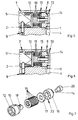
- FIG. 7 additionally shows the intermediate piece 10 from FIG. 2 with the friction plates 16, 17 and the clutch engagement member 14 in an exploded view.
- the screw 20 in the bolt 18 of the intermediate piece 10 can be the components shown in Figure 7 Pre-assemble into a unit and in the in Figure 1 Insert the locking cylinder shown.
Landscapes
- Engineering & Computer Science (AREA)
- Mechanical Engineering (AREA)
- Lock And Its Accessories (AREA)
- Bidirectional Digital Transmission (AREA)
Applications Claiming Priority (2)
| Application Number | Priority Date | Filing Date | Title |
|---|---|---|---|
| DE10317449 | 2003-04-16 | ||
| DE2003117449 DE10317449A1 (de) | 2003-04-16 | 2003-04-16 | Kupplungseinrichtung an Doppelschließzylinder und Doppelschließzylinder |
Publications (2)
| Publication Number | Publication Date |
|---|---|
| EP1469146A2 true EP1469146A2 (fr) | 2004-10-20 |
| EP1469146A3 EP1469146A3 (fr) | 2007-11-07 |
Family
ID=32892364
Family Applications (1)
| Application Number | Title | Priority Date | Filing Date |
|---|---|---|---|
| EP04100663A Withdrawn EP1469146A3 (fr) | 2003-04-16 | 2004-02-19 | Dispositif d'accouplement pour serrure à double cylindre et serrure à double cylindre avec un tel dispositif d'accouplement |
Country Status (2)
| Country | Link |
|---|---|
| EP (1) | EP1469146A3 (fr) |
| DE (1) | DE10317449A1 (fr) |
Cited By (5)
| Publication number | Priority date | Publication date | Assignee | Title |
|---|---|---|---|---|
| RU2387774C1 (ru) * | 2008-10-29 | 2010-04-27 | Станислав Михайлович Иванов | Способ отпирания замка и замок, реализующий способ |
| CN1995669B (zh) * | 2006-09-26 | 2011-05-04 | 雷先鸣 | 一种内置式插芯门锁的锁头 |
| EP1978190A3 (fr) * | 2007-04-04 | 2013-07-24 | Aug. Winkhaus GmbH & Co. KG | Serrure cylindrique |
| RU2528156C2 (ru) * | 2008-06-26 | 2014-09-10 | Авосет Хардвэа Лтд | Замковый механизм |
| EP4086414A1 (fr) * | 2021-05-07 | 2022-11-09 | ASSA ABLOY (Schweiz) AG | Agencement de cylindre de fermeture pourvu d'accouplement à poignée |
Citations (4)
| Publication number | Priority date | Publication date | Assignee | Title |
|---|---|---|---|---|
| DE3715972A1 (de) | 1987-05-13 | 1988-12-08 | Dom Sicherheitstechnik | Kupplungseinrichtung an doppel-schliesszylindern |
| EP0536653A1 (fr) | 1991-10-11 | 1993-04-14 | Costruzioni Italiane Serrature Affini C.I.S.A. S.p.A. | Serrure cylindrique |
| GB2334546A (en) | 1998-02-18 | 1999-08-25 | John Dudley Harwood | Lock cylinder with drive disconnection |
| DE19836166A1 (de) | 1998-08-10 | 2000-02-17 | Winkhaus Fa August | Kopplungseinrichtung für ein Zylinderschloß |
Family Cites Families (6)
| Publication number | Priority date | Publication date | Assignee | Title |
|---|---|---|---|---|
| JPH0533534A (ja) * | 1991-05-31 | 1993-02-09 | Alpha:Kk | シリンダ錠 |
| DE4233029C2 (de) * | 1992-10-01 | 2001-10-04 | Valeo Deutschland Gmbh & Co | Schließzylinder |
| DE4403622C2 (de) * | 1994-02-05 | 1997-09-18 | Michael Fleischmann | Türschloß |
| ES2088766B1 (es) * | 1994-05-19 | 1997-02-16 | Sistemas & Tec Seguridad | Dispositivo de adaptacion de bombillo a cerraduras y susceptible de funcion antipanico. |
| FR2757557B1 (fr) * | 1996-12-24 | 1999-02-19 | Deny | Serrure de surete |
| DE20100424U1 (de) * | 2001-01-11 | 2001-03-22 | C. Ed. Schulte GmbH Zylinderschloßfabrik, 42551 Velbert | Schließzylinder mit rutschgekuppeltem Drehknopf |
-
2003
- 2003-04-16 DE DE2003117449 patent/DE10317449A1/de not_active Withdrawn
-
2004
- 2004-02-19 EP EP04100663A patent/EP1469146A3/fr not_active Withdrawn
Patent Citations (4)
| Publication number | Priority date | Publication date | Assignee | Title |
|---|---|---|---|---|
| DE3715972A1 (de) | 1987-05-13 | 1988-12-08 | Dom Sicherheitstechnik | Kupplungseinrichtung an doppel-schliesszylindern |
| EP0536653A1 (fr) | 1991-10-11 | 1993-04-14 | Costruzioni Italiane Serrature Affini C.I.S.A. S.p.A. | Serrure cylindrique |
| GB2334546A (en) | 1998-02-18 | 1999-08-25 | John Dudley Harwood | Lock cylinder with drive disconnection |
| DE19836166A1 (de) | 1998-08-10 | 2000-02-17 | Winkhaus Fa August | Kopplungseinrichtung für ein Zylinderschloß |
Cited By (5)
| Publication number | Priority date | Publication date | Assignee | Title |
|---|---|---|---|---|
| CN1995669B (zh) * | 2006-09-26 | 2011-05-04 | 雷先鸣 | 一种内置式插芯门锁的锁头 |
| EP1978190A3 (fr) * | 2007-04-04 | 2013-07-24 | Aug. Winkhaus GmbH & Co. KG | Serrure cylindrique |
| RU2528156C2 (ru) * | 2008-06-26 | 2014-09-10 | Авосет Хардвэа Лтд | Замковый механизм |
| RU2387774C1 (ru) * | 2008-10-29 | 2010-04-27 | Станислав Михайлович Иванов | Способ отпирания замка и замок, реализующий способ |
| EP4086414A1 (fr) * | 2021-05-07 | 2022-11-09 | ASSA ABLOY (Schweiz) AG | Agencement de cylindre de fermeture pourvu d'accouplement à poignée |
Also Published As
| Publication number | Publication date |
|---|---|
| DE10317449A1 (de) | 2004-11-04 |
| EP1469146A3 (fr) | 2007-11-07 |
Similar Documents
| Publication | Publication Date | Title |
|---|---|---|
| DE4122414C1 (de) | Schließzylinder | |
| EP1182104B1 (fr) | Dispositif de verrouillage pour la colonne de direction d'un véhicule | |
| EP0436496B1 (fr) | Clé pour cylindre de fermeture, notamment pour système de verrouillage | |
| EP0819810B1 (fr) | Ferrure pour une serrure | |
| DE102007011554B4 (de) | Koppeleinheit für elektronische Schließ-Systeme | |
| EP1469146A2 (fr) | Dispositif d'accouplement pour serrure à double cylindre et serrure à double cylindre avec un tel dispositif d'accouplement | |
| DE19959833C1 (de) | Schließvorrichtung für insbesondere an Fahrzeugen vollziehbare Schließfunktionen | |
| DE2802408C2 (de) | Schließeinrichtung für Kraftfahrzeugtüren o.dgl. | |
| DE9417227U1 (de) | Verriegelungsschloß | |
| EP3550097B1 (fr) | Dispositif de fermeture | |
| DE10015095C2 (de) | Verriegelungsvorrichtung für einen Türflügel | |
| EP2738325B1 (fr) | Cylindre anti-panique | |
| DE10346956B3 (de) | Schließzylinder für ein Schloss, insbesondere bei Fahrzeugen | |
| AT506661A1 (de) | Kupplungseinrichtung an einem doppelschliesszylinder | |
| EP1156179A2 (fr) | Serrure cylindrique | |
| DE2828563A1 (de) | Schliesseinrichtung fuer kraftfahrzeugtueren o.dgl. | |
| DE102005026930B4 (de) | Vorhangschloss | |
| DE102004032157A1 (de) | Verschluss für Türen oder Klappen an Fahrzeugen | |
| DE4230591A1 (de) | Codierbares Zylinderschloß | |
| EP4112856A1 (fr) | Serrure dotée d'un verrou pouvant tourner à l'aide d'un élément d'actionnement | |
| DE102006010435B4 (de) | Schloss | |
| DE20202987U1 (de) | Schließzylinder | |
| DE102022114905A1 (de) | Schloss mit einem von einem Betätigungselement drehbaren Riegel | |
| DE3216481A1 (de) | Schluesselbetaetigter schliesszylinder | |
| DE102023125148A1 (de) | Vorreiberverschluss |
Legal Events
| Date | Code | Title | Description |
|---|---|---|---|
| PUAI | Public reference made under article 153(3) epc to a published international application that has entered the european phase |
Free format text: ORIGINAL CODE: 0009012 |
|
| AK | Designated contracting states |
Kind code of ref document: A2 Designated state(s): AT BE BG CH CY CZ DE DK EE ES FI FR GB GR HU IE IT LI LU MC NL PT RO SE SI SK TR |
|
| AX | Request for extension of the european patent |
Extension state: AL LT LV MK |
|
| PUAL | Search report despatched |
Free format text: ORIGINAL CODE: 0009013 |
|
| AK | Designated contracting states |
Kind code of ref document: A3 Designated state(s): AT BE BG CH CY CZ DE DK EE ES FI FR GB GR HU IE IT LI LU MC NL PT RO SE SI SK TR |
|
| AX | Request for extension of the european patent |
Extension state: AL LT LV MK |
|
| 17P | Request for examination filed |
Effective date: 20080317 |
|
| AKX | Designation fees paid |
Designated state(s): AT BE BG CH CY CZ DE DK EE ES FI FR GB GR HU IE IT LI LU MC NL PT RO SE SI SK TR |
|
| 17Q | First examination report despatched |
Effective date: 20100222 |
|
| STAA | Information on the status of an ep patent application or granted ep patent |
Free format text: STATUS: THE APPLICATION IS DEEMED TO BE WITHDRAWN |
|
| 18D | Application deemed to be withdrawn |
Effective date: 20120830 |