EP1469159A2 - Dispositif d'étanchéité pour porte - Google Patents
Dispositif d'étanchéité pour porte Download PDFInfo
- Publication number
- EP1469159A2 EP1469159A2 EP03026022A EP03026022A EP1469159A2 EP 1469159 A2 EP1469159 A2 EP 1469159A2 EP 03026022 A EP03026022 A EP 03026022A EP 03026022 A EP03026022 A EP 03026022A EP 1469159 A2 EP1469159 A2 EP 1469159A2
- Authority
- EP
- European Patent Office
- Prior art keywords
- trigger
- sealing device
- door
- door sealing
- adjustment
- Prior art date
- Legal status (The legal status is an assumption and is not a legal conclusion. Google has not performed a legal analysis and makes no representation as to the accuracy of the status listed.)
- Granted
Links
Images

Classifications
-
- E—FIXED CONSTRUCTIONS
- E06—DOORS, WINDOWS, SHUTTERS, OR ROLLER BLINDS IN GENERAL; LADDERS
- E06B—FIXED OR MOVABLE CLOSURES FOR OPENINGS IN BUILDINGS, VEHICLES, FENCES OR LIKE ENCLOSURES IN GENERAL, e.g. DOORS, WINDOWS, BLINDS, GATES
- E06B7/00—Special arrangements or measures in connection with doors or windows
- E06B7/16—Sealing arrangements on wings or parts co-operating with the wings
- E06B7/18—Sealing arrangements on wings or parts co-operating with the wings by means of movable edgings, e.g. draught sealings additionally used for bolting, e.g. by spring force or with operating lever
- E06B7/20—Sealing arrangements on wings or parts co-operating with the wings by means of movable edgings, e.g. draught sealings additionally used for bolting, e.g. by spring force or with operating lever automatically withdrawn when the wing is opened, e.g. by means of magnetic attraction, a pin or an inclined surface, especially for sills
- E06B7/215—Sealing arrangements on wings or parts co-operating with the wings by means of movable edgings, e.g. draught sealings additionally used for bolting, e.g. by spring force or with operating lever automatically withdrawn when the wing is opened, e.g. by means of magnetic attraction, a pin or an inclined surface, especially for sills with sealing strip being moved to a retracted position by elastic means, e.g. springs
-
- E—FIXED CONSTRUCTIONS
- E05—LOCKS; KEYS; WINDOW OR DOOR FITTINGS; SAFES
- E05D—HINGES OR SUSPENSION DEVICES FOR DOORS, WINDOWS OR WINGS
- E05D13/00—Accessories for sliding or lifting wings, e.g. pulleys, safety catches
-
- E—FIXED CONSTRUCTIONS
- E05—LOCKS; KEYS; WINDOW OR DOOR FITTINGS; SAFES
- E05Y—INDEXING SCHEME ASSOCIATED WITH SUBCLASSES E05D AND E05F, RELATING TO CONSTRUCTION ELEMENTS, ELECTRIC CONTROL, POWER SUPPLY, POWER SIGNAL OR TRANSMISSION, USER INTERFACES, MOUNTING OR COUPLING, DETAILS, ACCESSORIES, AUXILIARY OPERATIONS NOT OTHERWISE PROVIDED FOR, APPLICATION THEREOF
- E05Y2900/00—Application of doors, windows, wings or fittings thereof
- E05Y2900/10—Application of doors, windows, wings or fittings thereof for buildings or parts thereof
- E05Y2900/13—Type of wing
- E05Y2900/132—Doors
Definitions
- the present invention relates to a method for mounting and Adjustment of a door sealing device on a door leaf in order Sealing of a lower door gap, wherein the Door sealing device at least one band side and / or lock-side shutter covers and one the Door seal device initially mounted so that the trigger has a larger projection than necessary and then the Door closes, whereby by occurrence of a set value exceeding ground contact pressure of a sealing profile a Axial displacement of the trigger relative to one with this connected transmission element occurs.
- the subject of the present invention is furthermore a Door sealing device with the features of the preamble of Claim 4 and the use of such Door sealing device in a method of the aforementioned Art.
- Door sealing devices of the type mentioned are of a Carpenter or mechanic installed in a door leaf, for example grooved.
- a setting must be made ensures that the band side or castle side projecting Trigger as far as projecting that sufficient axial Displacement of the shutter when closing the door is done for the desired stroke of the sinking when closing Sealing profile provides.
- the band side or castle side projecting Trigger as far as projecting that sufficient axial Displacement of the shutter when closing the door is done for the desired stroke of the sinking when closing Sealing profile provides.
- the band side or castle side projecting Trigger as far as projecting that sufficient axial Displacement of the shutter when closing the door is done for the desired stroke of the sinking when closing Sealing profile provides.
- the band side or castle side projecting Trigger as far as projecting that sufficient axial Displacement of the shutter when closing the door is done for the desired stroke of the sinking when closing Sealing profile provides.
- the band side or castle side projecting Trigger as far as projecting that sufficient axial Displacement of the shutter
- This Bodenanpressung should not be too large, so that the Sealing profile by the ground contact pressure when closing the door not deformed too much.
- at least one has to Ground contact made that the gap to the ground effectively is sealed. Since in particular the band-side trigger for a Lowering the door seal to a certain extent already to a Time ensures, before the door has reached its closed position also to consider that by the Bodenanpressung the sealing profile dragging over the ground. An excessive ground pressure leads thus for wear or damage to the sealing device.
- the Setting the required Bodenanpressung the sealing profile is from the fitter about the corresponding position of the trigger performed. In some known sealing devices a tool needed or the trigger set is expensive constructed with a spring to pull out, making it relative time consuming until the right setting is found.
- EP-A-0841457 describes a door sealing device of the type mentioned, at the supernatant of the trigger is regulated by an as Transmission member serving threaded bolt more or less strong is screwed into an internal thread of the trigger.
- the adjustment is done by Turning the trigger element, which in particular at a square trigger element on the lock side often always one full rotation of the trigger must make, so no very fine setting is possible.
- FR 884 694 describes a door sealing device of the beginning said genus.
- the Release mechanism formed in two parts with a hollow rod, that with a lowering mechanism for a sealing rod connected is. Inside this hollow bar is one another rod, in the former rod over a certain Distance is axially displaceable.
- this known Door seal device is indeed when lowering by the spring created a compensation, the too high ground pressure of the Seal profile avoids.
- the object of the present invention is a method for mounting and adjusting a door sealing device of to create the aforementioned type, which wear at Sealing profile and mechanics avoids, is easy to assemble and a simple achievement of each with regard to the Ground pressure of the sealing profile according to the respective structural conditions optimal setting of the shutter allows. It is another object of the present invention to provide a To provide sealing device that in a process the aforementioned type is usable.
- the solution to this problem provides a method according to the invention for mounting and adjusting a door sealing device of aforementioned genus with the characterizing features of the main claim.
- the door sealing device according to the invention is the subject of claim 4.
- Subject of the invention continue the use of such a door sealing device according to claim 21 in the assembly method according to the invention.
- the transmission member comprises a rod, in particular a threaded rod and the shutter is designed to work with Exceeding the desired soil pressure of the Sealing profile over at least one thread of the Threaded rod jumps and thereby adjusted itself.
- the inventive method for mounting and adjustment of Door sealing device has compared to the conventional Approach a much greater benefit for the user.
- the initial adjustment was necessary is eliminated.
- the Door seal device for example, from the manufacturer in one Delivered delivered condition in which the trigger a supernatant which is greater than that necessary in the application Projection dimension.
- Self-adjustment will then the first time the door is closed Self-adjustment of the trigger reaches, in which this axially as far as a transmission link connected to this shifts that the ground contact pressure of the weatherstrip is minimized and get an optimal setting of Sealing device results.
- Said radial spread of the Triggers in Dijustiervorgang can be, for example through a slot in the wall of the trigger.
- a possible alternative to a trigger in self-adjustment over a thread is that one provided several in axially staggered arrangement Elastic elements in a hole of the trigger brings the one Transmitting member absorbs.
- the mentioned holding means can for example, be annular, for example, you can have a Use rubber ring or spring washer, which can be put on the trigger, the in this case, an externally approximately cylindrical part is deferred.
- the Trigger can also have a polygon outline. One can also, for example, on the circumference of the trigger grooves or a Provide profiling or corrugation, whereby the respective axial Displacement position of said holding means is defined.
- a deformation member in a bore of the Bring the trigger which is exceeded when the setpoint the ground contact pressure of the seal by a thrust, which is the Transfer member exerts on this deformation member, deformed. It So is preferably the axial extent of the deformation member reduced in the bore, this preferably without a Reversion occurs, that is, the deformation member is not elastically deformable, since the trigger after the adjustment should maintain appropriate position.
- structurally defined deformation member comes For example, a folded sheet or the like or a Hard foam or the like into consideration.
- Another possible alternative variant of the invention Solution provides that you have a transmission link, which is part of the Lowering mechanism of the seal is in a hole of the trigger receives with a press fit. In the self-adjustment pushes this Transfer member deeper into the hole, causing the Area proportion in the press fit and thus the back pressure increased, as long as until the corresponding position of the trigger is reached.
- One can also do a multiple self-adjustment in the field of Trigger and / or further inside the case of the Door sealing device lying parts of the release mechanism provide.
- door sealing devices are known, as described in DE 34 27 938 A1, which in the Trigger mechanism use several spring packs, so that one then has several parts where self-alignment occurs, Similar to the one described above for the trigger.
- the self-adjustment does not take place or not only at the outside of the door leaf protruding trigger, but on more Parts that lie inside the case.
- This approach is particularly suitable for wider doors with correspondingly long Door seal housings, in which often several spring assemblies used to get a uniform reduction over the length to achieve the door seal.
- the invention can provide that in addition to self-adjustment nor a manually adjustable Fine adjustment of the shutter is possible. This is for example then useful if the self-adjustment in still too crude steps takes place, for example by jumping over individual threads, so that an even more accurate adjustment of the shutter manually can, the intermediate positions between the individual positions of the Self-adjustment allows. It should be remembered that constructive conditionally a change in the axial setting of the shutter to a unit of length a multiple of change in the stroke of Sealing device can make out, making a very fine Adjustment makes sense. But it can also be the self-adjustment so Make that a finely graduated shift of the trigger becomes possible.
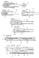
- FIG. 1a shows in two views a trigger 11 according to a possible variant of the invention, which is a such trigger, as he usually on the hinge side of the Door leaf is used. Therefore, the trigger 11 has a rounded dome 11a, which when closing the door on the door frame incident. To make the trigger 11 radially expandable, as is out the frontal view is visible, two in the longitudinal direction extending slots 13 provided in the wall of the bis on the crest 11a substantially cylindrical trigger extend.
- the trigger according to Fig. 1a has a cylindrical central bore 9, which is designed with an internal thread, such as can be seen in Fig. 1a in the right side view.
- This hole 10 takes a threaded rod 12, as can be seen in Figs. 7a and 7b can recognize.
- This threaded rod 12 with external thread 12a is used as a transfer member in the context of the present invention, which Part of a trigger mechanism is to stop the shift of the Trigger 11 when closing the door in a lowering movement of a To convert sealing profile 10, as shown in Figs. 8a and 8b is shown.
- the rod-shaped Transfer member 12 has an external thread 12a, which in the Thread of the hole 9 of the trigger engages. If the measure M of the Projection of the trigger (see Fig. 8b) is too large and the Ground contact pressure exceeds the set point, then spreads with the slots 13 provided trigger 11 and the threaded rod 12th Skips one or more threads of the internal thread in the bore 9, so that the threaded rod 12 continues in the Drill hole, as can be seen by comparing Figs. 7a and 7b can recognize.
- Fig. 1b shows a similar embodiment of a trigger 11, however has a different shape than the trigger shown in Fig. 1a.
- the trigger 11 of FIG. 1b is on the one hand angular, as can be seen from the recognizes the frontal view.
- the trigger has no dome but on its opposite the door leaf (not shown) projecting side a slope 8. This slope is present because it is a lock-side trigger. At the Lock side meets the door leaf during the closing process gradually on the Door frame, which is why the slope 8 is provided.
- Trigger of the in Fig. 1b are angular and are mostly of a groove, a holding rail or the like of the housing of Door sealing device added.
- the trigger is 11 otherwise similar to that of Fig. 1a.
- the trigger 11 of FIG. 1b has a bore 9 with internal thread, which is a rod-shaped Transmitter with external thread receives, similar to the Threaded rod 12 in Figs. 7a and 7b.
- the function of the shutter 11 of FIG. 1b is thus in principle self-aligning such that If the setpoint of the ground contact pressure is exceeded, the Threaded rod 12 further into the bore 9 of the trigger pushes.
- Fig. 2 shows a somewhat different embodiment, wherein the Although trigger 11 has a hole 9, but no Internal thread has, but several, for example, transverse to the bore 9 extending elastic elements 14 in axially offset from each other Arrangement.
- These elastic elements 14 are as shown in FIGS. 2 left and right recognizes alternately below and above in the Bore and always offset from each other in the axial direction arranged, wherein they extend transversely to the axial direction of the bore 9 and project tangentially into this hole in a sector-shaped manner (see left Representation of Fig. 2).
- Also in the trigger of Fig. 11 takes the Bore 9 again a rod-shaped transmission member 12 (in Fig.
- the trigger 11 a rubber thread 15 in the bore 9.
- the trigger 11 is at the trigger 11 to a hard / soft injection molded part.
- the shutter 11 with slots 13 may be the same Effect can be achieved as previously described in Fig. 1a, wherein it at the variant of FIG. 3 is not absolutely necessary, the shutter 11 with slots 13 to provide, because the rubber thread 15 leaves even without the trigger 11 spreads in the radial direction Continue slipping a threaded rod 12 in the bore 9 of the Trigger (skipping threads) when a Shearing force in the longitudinal direction, if this a certain Threshold exceeds.
- FIG. 4a Another embodiment of the invention described in more detail.
- the Illustrations show each for the band side provided release 11 provided with longitudinal slots 13, similar to the embodiment of FIG. 1a.
- a holding means for example in shape a rubber ring 16 is provided, which on the circumference of the Trigger 11 is pushed on, as shown in Fig. 4a.
- the Pick up rubber ring 16 there are several in the circumference of the trigger Longitudinally spaced grooves 17, the Pick up rubber ring 16. If you now have the rubber ring out of one further forward arrangement according to FIG.
- a higher thrust has to be provided be applied in order to achieve the same effect, since the Trigger 11 is held together by the rubber ring 16 stronger. Due to the different positions of the rubber ring 16 on the Extent of the trigger 11 in the grooves 17 can be the Make self-adjustment variable.
- Fig. 4c shows another Embodiment in which, however, the rubber ring 16 narrower is formed and a larger number of grooves 17 is present, so that a kind of corrugation on the outer circumference of the shutter 11 results. As a result, more displacement positions of the rubber ring 16 possible, which allow a finer vote.
- Rubber ring 16 may for example also used a spring washer become.
- a trigger 11 in particular for the band side of a Door leaf is suitable.
- the basic form is similar to that the trigger according to the embodiment of Fig. 1a.
- Transmission member 12 is here but a rod without External thread in a simple bore 18 without internal thread of the trigger 11 is received.
- Front side in front of Transmission member 12 is in the bore 18 a deformation member 19th arranged, for example, a folded sheet metal part consisting of a material that deforms when passing through the Transmission member 12 acts a thrust.
- a deformation member 19th arranged, for example, a folded sheet metal part consisting of a material that deforms when passing through the Transmission member 12 acts a thrust.
- Such Shear force occurs when lowering the door seal device the sealing profile 10 is subjected to a ground contact pressure, the over the components 24, 23, 22, 12 (see also Fig.
- the Trigger 8b) on the Trigger transmits.
- the trigger 11 of FIG. 5a then slides on the rod-shaped transmission member 12, whereby the Deforming member 19 is compressed and deformed by Upsetting.
- the deforming member 19 is deformed to an extent as it corresponds to the ground contact pressure of the sealing profile. It occurs during this no recovery, so that after self-adjustment the deformation member 19 and thus also the rod-shaped Transmission member 12 remains in the setting position then achieved.
- Fig. 5b shows a similar embodiment of the trigger 11, at also a rod-shaped transfer member 12 without External thread engages in a simple bore of the trigger 11.
- the deformation member 19 is designed differently here and consists of a hard foam, which is used in the self - adjustment of the End face of the transmission member 12 is pressed and then remains in the deformed compressed form.
- Fig. 6 shows another possible embodiment in which the Shutter 11 according to the invention is designed similarly as in the two previously described variants according to FIGS. 5a and 5b.
- a bore 18 is provided without internal thread and as Transfer member 12 is a simple rod.
- This rod 12 is inserted with a press fit into the bore 18 of the trigger.
- This interference fit achieves a similar effect as in Displacement of the transfer member 12 against a deforming member 19.
- the interference fit of the transfer member 12 in the bore 18th as shown in FIG. 6 is chosen so hard that up to a target value of Bodenanpressdrucks the sealing profile and a so connected thrust, which acts in the direction of arrow initially no Shift of the transmission member 12 occurs.
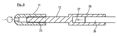
- FIG. 9 shows a trigger 11 and a rod-shaped transmission member 12, which front with a thread 25 is provided.
- This thread 25 is in a Threaded hole of the trigger 11 is screwed.
- a further transmission member 26th provided in the form of a rod, which with a press fit in one Bore 27 of a hollow cylindrical portion 28 is received.
- This hollow cylindrical portion 28 is at the thread 25th opposite end connected to the rod 12.
- connection between the rod 26 and the hollow cylindrical portion 28th includes a press fit such that upon occurrence of a thrust in axial direction, due to an increased ground contact pressure the sealing profile (not shown here) similar to the previously Based on Fig. 6 described embodiment Displacement of the rod 26 in the bore 27 in the arrow direction occurs, by the supernatant of the trigger 11 against the door leaf is reduced.
- the thread 25 is a ordinary thread and thus not one in which a Thread jump is provided. With a thrust so only one occurs Displacement of the rod 26 in the hollow cylindrical portion 28th but not a shift between the section with Thread 25 and the trigger 11. It is for a fine adjustment However, it is possible to rotate the trigger 11 and thus independently from the self-adjustment still make a fine adjustment at the supernatant of the trigger 11 in narrower areas is regulated.
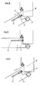
- Fig. 10 shows in a schematically simplified plan view of a section in the area a door frame 30 with a door leaf 31 on the hinge side.
- the Hinge 32 is shown schematically.
- X projecting trigger 11
Landscapes
- Engineering & Computer Science (AREA)
- Civil Engineering (AREA)
- Structural Engineering (AREA)
- Specific Sealing Or Ventilating Devices For Doors And Windows (AREA)
Priority Applications (1)
| Application Number | Priority Date | Filing Date | Title |
|---|---|---|---|
| US10/820,884 US7260915B2 (en) | 2003-04-15 | 2004-04-09 | Door seal device |
Applications Claiming Priority (2)
| Application Number | Priority Date | Filing Date | Title |
|---|---|---|---|
| DE20306091U | 2003-04-15 | ||
| DE20306091U DE20306091U1 (de) | 2003-04-15 | 2003-04-15 | Türdichtungsvorrichtung |
Publications (3)
| Publication Number | Publication Date |
|---|---|
| EP1469159A2 true EP1469159A2 (fr) | 2004-10-20 |
| EP1469159A3 EP1469159A3 (fr) | 2009-07-29 |
| EP1469159B1 EP1469159B1 (fr) | 2016-01-20 |
Family
ID=7981531
Family Applications (1)
| Application Number | Title | Priority Date | Filing Date |
|---|---|---|---|
| EP03026022.8A Expired - Lifetime EP1469159B1 (fr) | 2003-04-15 | 2003-11-12 | Dispositif d'étanchéité pour porte |
Country Status (3)
| Country | Link |
|---|---|
| EP (1) | EP1469159B1 (fr) |
| DE (1) | DE20306091U1 (fr) |
| DK (1) | DK1469159T3 (fr) |
Cited By (3)
| Publication number | Priority date | Publication date | Assignee | Title |
|---|---|---|---|---|
| WO2015019089A3 (fr) * | 2013-08-09 | 2015-05-07 | Lorient Polyproducts Limited | Joint de seuil et élément de joint allongé |
| DE202016100815U1 (de) | 2015-10-23 | 2016-03-24 | Athmer Ohg | Automatisch ausfahrbare Türspaltdichtung |
| DE102016108385B4 (de) | 2016-05-05 | 2022-08-04 | Athmer Ohg | Türspaltdichtung |
Families Citing this family (2)
| Publication number | Priority date | Publication date | Assignee | Title |
|---|---|---|---|---|
| DE202007016379U1 (de) * | 2007-11-21 | 2009-04-09 | F. Athmer Ohg | Absenkbare Bodendichtung mit zumindest teilweise weichem Auslöseelement |
| DK3699384T3 (da) * | 2019-02-20 | 2022-10-24 | Athmer Ohg | Tætning med en sænkbar tætningsliste, der kan sænkes ved hjælp af en sænkningsmekanisme, der kan betjenes af en udløser |
Family Cites Families (5)
| Publication number | Priority date | Publication date | Assignee | Title |
|---|---|---|---|---|
| FR884694A (fr) | 1941-02-12 | 1943-08-24 | Barre de joint pour portes | |
| DE3943526C2 (de) | 1989-10-27 | 1994-03-03 | Hahn Gmbh & Co Kg Dr | Schubstange einer automatischen Bodendichtung für eine Tür |
| US5083400A (en) * | 1990-10-29 | 1992-01-28 | Howard Bowman | Adjustable threshold and door sill |
| JPH1068278A (ja) | 1996-08-28 | 1998-03-10 | K G Partek Kk | 扉下部の隙間遮蔽装置 |
| IT1296362B1 (it) * | 1997-11-05 | 1999-06-25 | Luigi Geron | Dispositivo paraspifferi autoregolante |
-
2003
- 2003-04-15 DE DE20306091U patent/DE20306091U1/de not_active Expired - Lifetime
- 2003-11-12 EP EP03026022.8A patent/EP1469159B1/fr not_active Expired - Lifetime
- 2003-11-12 DK DK03026022.8T patent/DK1469159T3/en active
Cited By (6)
| Publication number | Priority date | Publication date | Assignee | Title |
|---|---|---|---|---|
| WO2015019089A3 (fr) * | 2013-08-09 | 2015-05-07 | Lorient Polyproducts Limited | Joint de seuil et élément de joint allongé |
| AU2014304295B2 (en) * | 2013-08-09 | 2018-05-17 | Assa Abloy Limited | Threshold seal and elongate seal member |
| DE202016100815U1 (de) | 2015-10-23 | 2016-03-24 | Athmer Ohg | Automatisch ausfahrbare Türspaltdichtung |
| DE102016117669A1 (de) | 2015-10-23 | 2017-04-27 | Athmer Ohg | Automatisch ausfahrbare Türspaltdichtung |
| DE102016117669B4 (de) | 2015-10-23 | 2022-10-20 | Athmer Ohg | Automatisch ausfahrbare Türspaltdichtung |
| DE102016108385B4 (de) | 2016-05-05 | 2022-08-04 | Athmer Ohg | Türspaltdichtung |
Also Published As
| Publication number | Publication date |
|---|---|
| DK1469159T3 (en) | 2016-04-25 |
| EP1469159B1 (fr) | 2016-01-20 |
| EP1469159A3 (fr) | 2009-07-29 |
| DE20306091U1 (de) | 2003-07-03 |
Similar Documents
| Publication | Publication Date | Title |
|---|---|---|
| EP2463563B1 (fr) | Support a force portante constante | |
| EP3973131B1 (fr) | Ferrure pour meuble | |
| EP0744009B1 (fr) | Vanne de regulation a etages multiples | |
| EP1711390B1 (fr) | Palier reglable par clavette pour mecanisme de direction de vehicule automobile | |
| DE10347528B3 (de) | Türöffner | |
| DE19632917B4 (de) | Bremsenjustiermechanismus | |
| DE102013011469A1 (de) | Führungseinrichtung für eine Schwimmsattel-Scheibenbremse | |
| EP1725797B1 (fr) | Soupape | |
| DE102017117573A1 (de) | Dichtungsvorrichtung, damit versehener Schiebetürflügel sowie damit versehene Schiebetür | |
| EP0571936A1 (fr) | Charnière, en particulier pour portes de meubles | |
| EP2165033B1 (fr) | Boulon de fermeture | |
| EP3277900B1 (fr) | Tenon de fermeture | |
| EP1469159A2 (fr) | Dispositif d'étanchéité pour porte | |
| DE102004042399A1 (de) | Kupplungsaggregat | |
| EP3667010B1 (fr) | Dispositif de butée pour un joint de porte automatique, en particulier pour une porte pivotante ou battante, agencement d'un joint de porte automatique et d'un dispositif de butée | |
| DE2909749A1 (de) | Duebel und werkzeug zum befestigen des duebels | |
| EP2620575B1 (fr) | Dispositif d'assistance d'ouverture pour une fenêtre, une porte ou analogue ainsi que la fenêtre correspondante | |
| EP0099028B1 (fr) | Cheville à poids lourd en métal | |
| AT523901B1 (de) | Selbstsichernder Vorspannring für Federbeine | |
| DE202007016379U1 (de) | Absenkbare Bodendichtung mit zumindest teilweise weichem Auslöseelement | |
| EP2295686B1 (fr) | Cheville de fermeture pour une armature de verrouillage de fenêtre ou de porte | |
| EP2209961B1 (fr) | Procédé de fabrication d'un boulon de fermeture | |
| EP2362045B1 (fr) | Porte pour une armoire électrique | |
| DE102017112004A1 (de) | Beschlaganordnung | |
| EP0568858A2 (fr) | Dispositif de verrouillage d'un piston commandé par pression, en particulier pour la commande d'une barre antirenversement d'un véhicule |
Legal Events
| Date | Code | Title | Description |
|---|---|---|---|
| PUAI | Public reference made under article 153(3) epc to a published international application that has entered the european phase |
Free format text: ORIGINAL CODE: 0009012 |
|
| AK | Designated contracting states |
Kind code of ref document: A2 Designated state(s): AT BE BG CH CY CZ DE DK EE ES FI FR GB GR HU IE IT LI LU MC NL PT RO SE SI SK TR |
|
| AX | Request for extension of the european patent |
Extension state: AL LT LV MK |
|
| PUAL | Search report despatched |
Free format text: ORIGINAL CODE: 0009013 |
|
| AK | Designated contracting states |
Kind code of ref document: A3 Designated state(s): AT BE BG CH CY CZ DE DK EE ES FI FR GB GR HU IE IT LI LU MC NL PT RO SE SI SK TR |
|
| AX | Request for extension of the european patent |
Extension state: AL LT LV MK |
|
| 17P | Request for examination filed |
Effective date: 20100129 |
|
| AKX | Designation fees paid |
Designated state(s): AT BE BG CH CY CZ DE DK EE ES FI FR GB GR HU IE IT LI LU MC NL PT RO SE SI SK TR |
|
| 17Q | First examination report despatched |
Effective date: 20100312 |
|
| GRAP | Despatch of communication of intention to grant a patent |
Free format text: ORIGINAL CODE: EPIDOSNIGR1 |
|
| INTG | Intention to grant announced |
Effective date: 20150717 |
|
| GRAS | Grant fee paid |
Free format text: ORIGINAL CODE: EPIDOSNIGR3 |
|
| GRAA | (expected) grant |
Free format text: ORIGINAL CODE: 0009210 |
|
| AK | Designated contracting states |
Kind code of ref document: B1 Designated state(s): AT BE BG CH CY CZ DE DK EE ES FI FR GB GR HU IE IT LI LU MC NL PT RO SE SI SK TR |
|
| REG | Reference to a national code |
Ref country code: GB Ref legal event code: FG4D Free format text: NOT ENGLISH |
|
| REG | Reference to a national code |
Ref country code: CH Ref legal event code: EP |
|
| REG | Reference to a national code |
Ref country code: IE Ref legal event code: FG4D Free format text: LANGUAGE OF EP DOCUMENT: GERMAN |
|
| REG | Reference to a national code |
Ref country code: AT Ref legal event code: REF Ref document number: 771809 Country of ref document: AT Kind code of ref document: T Effective date: 20160215 |
|
| REG | Reference to a national code |
Ref country code: DE Ref legal event code: R096 Ref document number: 50315403 Country of ref document: DE |
|
| REG | Reference to a national code |
Ref country code: DK Ref legal event code: T3 Effective date: 20160421 |
|
| REG | Reference to a national code |
Ref country code: SE Ref legal event code: TRGR |
|
| REG | Reference to a national code |
Ref country code: NL Ref legal event code: FP |
|
| PG25 | Lapsed in a contracting state [announced via postgrant information from national office to epo] |
Ref country code: GR Free format text: LAPSE BECAUSE OF FAILURE TO SUBMIT A TRANSLATION OF THE DESCRIPTION OR TO PAY THE FEE WITHIN THE PRESCRIBED TIME-LIMIT Effective date: 20160421 Ref country code: ES Free format text: LAPSE BECAUSE OF FAILURE TO SUBMIT A TRANSLATION OF THE DESCRIPTION OR TO PAY THE FEE WITHIN THE PRESCRIBED TIME-LIMIT Effective date: 20160120 Ref country code: FI Free format text: LAPSE BECAUSE OF FAILURE TO SUBMIT A TRANSLATION OF THE DESCRIPTION OR TO PAY THE FEE WITHIN THE PRESCRIBED TIME-LIMIT Effective date: 20160120 |
|
| PG25 | Lapsed in a contracting state [announced via postgrant information from national office to epo] |
Ref country code: PT Free format text: LAPSE BECAUSE OF FAILURE TO SUBMIT A TRANSLATION OF THE DESCRIPTION OR TO PAY THE FEE WITHIN THE PRESCRIBED TIME-LIMIT Effective date: 20160520 |
|
| REG | Reference to a national code |
Ref country code: DE Ref legal event code: R097 Ref document number: 50315403 Country of ref document: DE |
|
| PG25 | Lapsed in a contracting state [announced via postgrant information from national office to epo] |
Ref country code: EE Free format text: LAPSE BECAUSE OF FAILURE TO SUBMIT A TRANSLATION OF THE DESCRIPTION OR TO PAY THE FEE WITHIN THE PRESCRIBED TIME-LIMIT Effective date: 20160120 |
|
| REG | Reference to a national code |
Ref country code: FR Ref legal event code: PLFP Year of fee payment: 14 |
|
| PLBE | No opposition filed within time limit |
Free format text: ORIGINAL CODE: 0009261 |
|
| STAA | Information on the status of an ep patent application or granted ep patent |
Free format text: STATUS: NO OPPOSITION FILED WITHIN TIME LIMIT |
|
| PG25 | Lapsed in a contracting state [announced via postgrant information from national office to epo] |
Ref country code: CZ Free format text: LAPSE BECAUSE OF FAILURE TO SUBMIT A TRANSLATION OF THE DESCRIPTION OR TO PAY THE FEE WITHIN THE PRESCRIBED TIME-LIMIT Effective date: 20160120 Ref country code: RO Free format text: LAPSE BECAUSE OF FAILURE TO SUBMIT A TRANSLATION OF THE DESCRIPTION OR TO PAY THE FEE WITHIN THE PRESCRIBED TIME-LIMIT Effective date: 20160120 Ref country code: SK Free format text: LAPSE BECAUSE OF FAILURE TO SUBMIT A TRANSLATION OF THE DESCRIPTION OR TO PAY THE FEE WITHIN THE PRESCRIBED TIME-LIMIT Effective date: 20160120 |
|
| 26N | No opposition filed |
Effective date: 20161021 |
|
| PGFP | Annual fee paid to national office [announced via postgrant information from national office to epo] |
Ref country code: IE Payment date: 20161122 Year of fee payment: 14 |
|
| PG25 | Lapsed in a contracting state [announced via postgrant information from national office to epo] |
Ref country code: SI Free format text: LAPSE BECAUSE OF FAILURE TO SUBMIT A TRANSLATION OF THE DESCRIPTION OR TO PAY THE FEE WITHIN THE PRESCRIBED TIME-LIMIT Effective date: 20160120 Ref country code: BE Free format text: LAPSE BECAUSE OF NON-PAYMENT OF DUE FEES Effective date: 20161130 Ref country code: BG Free format text: LAPSE BECAUSE OF FAILURE TO SUBMIT A TRANSLATION OF THE DESCRIPTION OR TO PAY THE FEE WITHIN THE PRESCRIBED TIME-LIMIT Effective date: 20160420 |
|
| PG25 | Lapsed in a contracting state [announced via postgrant information from national office to epo] |
Ref country code: LU Free format text: LAPSE BECAUSE OF NON-PAYMENT OF DUE FEES Effective date: 20161130 |
|
| REG | Reference to a national code |
Ref country code: FR Ref legal event code: PLFP Year of fee payment: 15 |
|
| REG | Reference to a national code |
Ref country code: BE Ref legal event code: MM Effective date: 20161130 |
|
| PGFP | Annual fee paid to national office [announced via postgrant information from national office to epo] |
Ref country code: IT Payment date: 20171123 Year of fee payment: 15 |
|
| PG25 | Lapsed in a contracting state [announced via postgrant information from national office to epo] |
Ref country code: HU Free format text: LAPSE BECAUSE OF FAILURE TO SUBMIT A TRANSLATION OF THE DESCRIPTION OR TO PAY THE FEE WITHIN THE PRESCRIBED TIME-LIMIT; INVALID AB INITIO Effective date: 20031112 Ref country code: CY Free format text: LAPSE BECAUSE OF FAILURE TO SUBMIT A TRANSLATION OF THE DESCRIPTION OR TO PAY THE FEE WITHIN THE PRESCRIBED TIME-LIMIT Effective date: 20160120 |
|
| PG25 | Lapsed in a contracting state [announced via postgrant information from national office to epo] |
Ref country code: MC Free format text: LAPSE BECAUSE OF FAILURE TO SUBMIT A TRANSLATION OF THE DESCRIPTION OR TO PAY THE FEE WITHIN THE PRESCRIBED TIME-LIMIT Effective date: 20160120 Ref country code: TR Free format text: LAPSE BECAUSE OF FAILURE TO SUBMIT A TRANSLATION OF THE DESCRIPTION OR TO PAY THE FEE WITHIN THE PRESCRIBED TIME-LIMIT Effective date: 20160120 |
|
| REG | Reference to a national code |
Ref country code: IE Ref legal event code: MM4A |
|
| PG25 | Lapsed in a contracting state [announced via postgrant information from national office to epo] |
Ref country code: IE Free format text: LAPSE BECAUSE OF NON-PAYMENT OF DUE FEES Effective date: 20171112 |
|
| PG25 | Lapsed in a contracting state [announced via postgrant information from national office to epo] |
Ref country code: IT Free format text: LAPSE BECAUSE OF NON-PAYMENT OF DUE FEES Effective date: 20181112 |
|
| PGFP | Annual fee paid to national office [announced via postgrant information from national office to epo] |
Ref country code: SE Payment date: 20211118 Year of fee payment: 19 Ref country code: DE Payment date: 20211130 Year of fee payment: 19 Ref country code: AT Payment date: 20211119 Year of fee payment: 19 Ref country code: NL Payment date: 20211118 Year of fee payment: 19 Ref country code: GB Payment date: 20211118 Year of fee payment: 19 Ref country code: FR Payment date: 20211122 Year of fee payment: 19 Ref country code: DK Payment date: 20211122 Year of fee payment: 19 |
|
| PGFP | Annual fee paid to national office [announced via postgrant information from national office to epo] |
Ref country code: CH Payment date: 20211119 Year of fee payment: 19 |
|
| REG | Reference to a national code |
Ref country code: DE Ref legal event code: R119 Ref document number: 50315403 Country of ref document: DE |
|
| REG | Reference to a national code |
Ref country code: DK Ref legal event code: EBP Effective date: 20221130 |
|
| REG | Reference to a national code |
Ref country code: CH Ref legal event code: PL |
|
| REG | Reference to a national code |
Ref country code: SE Ref legal event code: EUG |
|
| REG | Reference to a national code |
Ref country code: NL Ref legal event code: MM Effective date: 20221201 |
|
| REG | Reference to a national code |
Ref country code: AT Ref legal event code: MM01 Ref document number: 771809 Country of ref document: AT Kind code of ref document: T Effective date: 20221112 |
|
| GBPC | Gb: european patent ceased through non-payment of renewal fee |
Effective date: 20221112 |
|
| PG25 | Lapsed in a contracting state [announced via postgrant information from national office to epo] |
Ref country code: LI Free format text: LAPSE BECAUSE OF NON-PAYMENT OF DUE FEES Effective date: 20221130 Ref country code: CH Free format text: LAPSE BECAUSE OF NON-PAYMENT OF DUE FEES Effective date: 20221130 Ref country code: AT Free format text: LAPSE BECAUSE OF NON-PAYMENT OF DUE FEES Effective date: 20221112 |
|
| PG25 | Lapsed in a contracting state [announced via postgrant information from national office to epo] |
Ref country code: SE Free format text: LAPSE BECAUSE OF NON-PAYMENT OF DUE FEES Effective date: 20221113 Ref country code: NL Free format text: LAPSE BECAUSE OF NON-PAYMENT OF DUE FEES Effective date: 20221201 |
|
| PG25 | Lapsed in a contracting state [announced via postgrant information from national office to epo] |
Ref country code: GB Free format text: LAPSE BECAUSE OF NON-PAYMENT OF DUE FEES Effective date: 20221112 Ref country code: DK Free format text: LAPSE BECAUSE OF NON-PAYMENT OF DUE FEES Effective date: 20221130 Ref country code: DE Free format text: LAPSE BECAUSE OF NON-PAYMENT OF DUE FEES Effective date: 20230601 |
|
| PG25 | Lapsed in a contracting state [announced via postgrant information from national office to epo] |
Ref country code: FR Free format text: LAPSE BECAUSE OF NON-PAYMENT OF DUE FEES Effective date: 20221130 |