EP1469513A2 - Dispositif de traitement thermique ou dissipateur de chaleur à faible coût fabriqué à partir de matériaux conducteurs à base de résine - Google Patents
Dispositif de traitement thermique ou dissipateur de chaleur à faible coût fabriqué à partir de matériaux conducteurs à base de résine Download PDFInfo
- Publication number
- EP1469513A2 EP1469513A2 EP04368030A EP04368030A EP1469513A2 EP 1469513 A2 EP1469513 A2 EP 1469513A2 EP 04368030 A EP04368030 A EP 04368030A EP 04368030 A EP04368030 A EP 04368030A EP 1469513 A2 EP1469513 A2 EP 1469513A2
- Authority
- EP
- European Patent Office
- Prior art keywords
- conductive
- resin
- based material
- heat sink
- heat
- Prior art date
- Legal status (The legal status is an assumption and is not a legal conclusion. Google has not performed a legal analysis and makes no representation as to the accuracy of the status listed.)
- Withdrawn
Links
Images


Classifications
-
- G—PHYSICS
- G01—MEASURING; TESTING
- G01B—MEASURING LENGTH, THICKNESS OR SIMILAR LINEAR DIMENSIONS; MEASURING ANGLES; MEASURING AREAS; MEASURING IRREGULARITIES OF SURFACES OR CONTOURS
- G01B13/00—Measuring arrangements characterised by the use of fluids
- G01B13/02—Measuring arrangements characterised by the use of fluids for measuring length, width or thickness
- G01B13/06—Measuring arrangements characterised by the use of fluids for measuring length, width or thickness for measuring thickness
-
- B—PERFORMING OPERATIONS; TRANSPORTING
- B29—WORKING OF PLASTICS; WORKING OF SUBSTANCES IN A PLASTIC STATE IN GENERAL
- B29C—SHAPING OR JOINING OF PLASTICS; SHAPING OF MATERIAL IN A PLASTIC STATE, NOT OTHERWISE PROVIDED FOR; AFTER-TREATMENT OF THE SHAPED PRODUCTS, e.g. REPAIRING
- B29C45/00—Injection moulding, i.e. forcing the required volume of moulding material through a nozzle into a closed mould; Apparatus therefor
- B29C45/0013—Injection moulding, i.e. forcing the required volume of moulding material through a nozzle into a closed mould; Apparatus therefor using fillers dispersed in the moulding material, e.g. metal particles
-
- F—MECHANICAL ENGINEERING; LIGHTING; HEATING; WEAPONS; BLASTING
- F21—LIGHTING
- F21V—FUNCTIONAL FEATURES OR DETAILS OF LIGHTING DEVICES OR SYSTEMS THEREOF; STRUCTURAL COMBINATIONS OF LIGHTING DEVICES WITH OTHER ARTICLES, NOT OTHERWISE PROVIDED FOR
- F21V29/00—Protecting lighting devices from thermal damage; Cooling or heating arrangements specially adapted for lighting devices or systems
- F21V29/50—Cooling arrangements
- F21V29/60—Cooling arrangements characterised by the use of a forced flow of gas, e.g. air
- F21V29/67—Cooling arrangements characterised by the use of a forced flow of gas, e.g. air characterised by the arrangement of fans
- F21V29/677—Cooling arrangements characterised by the use of a forced flow of gas, e.g. air characterised by the arrangement of fans the fans being used for discharging
-
- F—MECHANICAL ENGINEERING; LIGHTING; HEATING; WEAPONS; BLASTING
- F21—LIGHTING
- F21V—FUNCTIONAL FEATURES OR DETAILS OF LIGHTING DEVICES OR SYSTEMS THEREOF; STRUCTURAL COMBINATIONS OF LIGHTING DEVICES WITH OTHER ARTICLES, NOT OTHERWISE PROVIDED FOR
- F21V29/00—Protecting lighting devices from thermal damage; Cooling or heating arrangements specially adapted for lighting devices or systems
- F21V29/50—Cooling arrangements
- F21V29/70—Cooling arrangements characterised by passive heat-dissipating elements, e.g. heat-sinks
- F21V29/74—Cooling arrangements characterised by passive heat-dissipating elements, e.g. heat-sinks with fins or blades
- F21V29/76—Cooling arrangements characterised by passive heat-dissipating elements, e.g. heat-sinks with fins or blades with essentially identical parallel planar fins or blades, e.g. with comb-like cross-section
-
- F—MECHANICAL ENGINEERING; LIGHTING; HEATING; WEAPONS; BLASTING
- F21—LIGHTING
- F21V—FUNCTIONAL FEATURES OR DETAILS OF LIGHTING DEVICES OR SYSTEMS THEREOF; STRUCTURAL COMBINATIONS OF LIGHTING DEVICES WITH OTHER ARTICLES, NOT OTHERWISE PROVIDED FOR
- F21V29/00—Protecting lighting devices from thermal damage; Cooling or heating arrangements specially adapted for lighting devices or systems
- F21V29/85—Protecting lighting devices from thermal damage; Cooling or heating arrangements specially adapted for lighting devices or systems characterised by the material
- F21V29/89—Metals
-
- F—MECHANICAL ENGINEERING; LIGHTING; HEATING; WEAPONS; BLASTING
- F28—HEAT EXCHANGE IN GENERAL
- F28D—HEAT-EXCHANGE APPARATUS, NOT PROVIDED FOR IN ANOTHER SUBCLASS, IN WHICH THE HEAT-EXCHANGE MEDIA DO NOT COME INTO DIRECT CONTACT
- F28D15/00—Heat-exchange apparatus with the intermediate heat-transfer medium in closed tubes passing into or through the conduit walls ; Heat-exchange apparatus employing intermediate heat-transfer medium or bodies
- F28D15/02—Heat-exchange apparatus with the intermediate heat-transfer medium in closed tubes passing into or through the conduit walls ; Heat-exchange apparatus employing intermediate heat-transfer medium or bodies in which the medium condenses and evaporates, e.g. heat pipes
- F28D15/04—Heat-exchange apparatus with the intermediate heat-transfer medium in closed tubes passing into or through the conduit walls ; Heat-exchange apparatus employing intermediate heat-transfer medium or bodies in which the medium condenses and evaporates, e.g. heat pipes with tubes having a capillary structure
-
- F—MECHANICAL ENGINEERING; LIGHTING; HEATING; WEAPONS; BLASTING
- F28—HEAT EXCHANGE IN GENERAL
- F28F—DETAILS OF HEAT-EXCHANGE AND HEAT-TRANSFER APPARATUS, OF GENERAL APPLICATION
- F28F21/00—Constructions of heat-exchange apparatus characterised by the selection of particular materials
- F28F21/06—Constructions of heat-exchange apparatus characterised by the selection of particular materials of plastics material
- F28F21/062—Constructions of heat-exchange apparatus characterised by the selection of particular materials of plastics material the heat-exchange apparatus employing tubular conduits
-
- G—PHYSICS
- G06—COMPUTING OR CALCULATING; COUNTING
- G06K—GRAPHICAL DATA READING; PRESENTATION OF DATA; RECORD CARRIERS; HANDLING RECORD CARRIERS
- G06K19/00—Record carriers for use with machines and with at least a part designed to carry digital markings
- G06K19/06—Record carriers for use with machines and with at least a part designed to carry digital markings characterised by the kind of the digital marking, e.g. shape, nature, code
- G06K19/067—Record carriers with conductive marks, printed circuits or semiconductor circuit elements, e.g. credit or identity cards also with resonating or responding marks without active components
- G06K19/07—Record carriers with conductive marks, printed circuits or semiconductor circuit elements, e.g. credit or identity cards also with resonating or responding marks without active components with integrated circuit chips
- G06K19/077—Constructional details, e.g. mounting of circuits in the carrier
- G06K19/07749—Constructional details, e.g. mounting of circuits in the carrier the record carrier being capable of non-contact communication, e.g. constructional details of the antenna of a non-contact smart card
-
- H—ELECTRICITY
- H05—ELECTRIC TECHNIQUES NOT OTHERWISE PROVIDED FOR
- H05K—PRINTED CIRCUITS; CASINGS OR CONSTRUCTIONAL DETAILS OF ELECTRIC APPARATUS; MANUFACTURE OF ASSEMBLAGES OF ELECTRICAL COMPONENTS
- H05K3/00—Apparatus or processes for manufacturing printed circuits
- H05K3/10—Apparatus or processes for manufacturing printed circuits in which conductive material is applied to the insulating support in such a manner as to form the desired conductive pattern
- H05K3/101—Apparatus or processes for manufacturing printed circuits in which conductive material is applied to the insulating support in such a manner as to form the desired conductive pattern by casting or moulding of conductive material
-
- H—ELECTRICITY
- H10—SEMICONDUCTOR DEVICES; ELECTRIC SOLID-STATE DEVICES NOT OTHERWISE PROVIDED FOR
- H10W—GENERIC PACKAGES, INTERCONNECTIONS, CONNECTORS OR OTHER CONSTRUCTIONAL DETAILS OF DEVICES COVERED BY CLASS H10
- H10W40/00—Arrangements for thermal protection or thermal control
- H10W40/20—Arrangements for cooling
- H10W40/25—Arrangements for cooling characterised by their materials
- H10W40/251—Organics
-
- H—ELECTRICITY
- H10—SEMICONDUCTOR DEVICES; ELECTRIC SOLID-STATE DEVICES NOT OTHERWISE PROVIDED FOR
- H10W—GENERIC PACKAGES, INTERCONNECTIONS, CONNECTORS OR OTHER CONSTRUCTIONAL DETAILS OF DEVICES COVERED BY CLASS H10
- H10W40/00—Arrangements for thermal protection or thermal control
- H10W40/70—Fillings or auxiliary members in containers or in encapsulations for thermal protection or control
- H10W40/73—Fillings or auxiliary members in containers or in encapsulations for thermal protection or control for cooling by change of state
-
- H—ELECTRICITY
- H10—SEMICONDUCTOR DEVICES; ELECTRIC SOLID-STATE DEVICES NOT OTHERWISE PROVIDED FOR
- H10W—GENERIC PACKAGES, INTERCONNECTIONS, CONNECTORS OR OTHER CONSTRUCTIONAL DETAILS OF DEVICES COVERED BY CLASS H10
- H10W70/00—Package substrates; Interposers; Redistribution layers [RDL]
- H10W70/01—Manufacture or treatment
- H10W70/02—Manufacture or treatment of conductive package substrates serving as an interconnection, e.g. of metal plates
- H10W70/027—Mechanical treatments, e.g. deforming, punching or cutting
-
- B—PERFORMING OPERATIONS; TRANSPORTING
- B29—WORKING OF PLASTICS; WORKING OF SUBSTANCES IN A PLASTIC STATE IN GENERAL
- B29C—SHAPING OR JOINING OF PLASTICS; SHAPING OF MATERIAL IN A PLASTIC STATE, NOT OTHERWISE PROVIDED FOR; AFTER-TREATMENT OF THE SHAPED PRODUCTS, e.g. REPAIRING
- B29C45/00—Injection moulding, i.e. forcing the required volume of moulding material through a nozzle into a closed mould; Apparatus therefor
- B29C45/0001—Injection moulding, i.e. forcing the required volume of moulding material through a nozzle into a closed mould; Apparatus therefor characterised by the choice of material
-
- B—PERFORMING OPERATIONS; TRANSPORTING
- B29—WORKING OF PLASTICS; WORKING OF SUBSTANCES IN A PLASTIC STATE IN GENERAL
- B29K—INDEXING SCHEME ASSOCIATED WITH SUBCLASSES B29B, B29C OR B29D, RELATING TO MOULDING MATERIALS OR TO MATERIALS FOR MOULDS, REINFORCEMENTS, FILLERS OR PREFORMED PARTS, e.g. INSERTS
- B29K2995/00—Properties of moulding materials, reinforcements, fillers, preformed parts or moulds
- B29K2995/0003—Properties of moulding materials, reinforcements, fillers, preformed parts or moulds having particular electrical or magnetic properties, e.g. piezoelectric
- B29K2995/0005—Conductive
-
- B—PERFORMING OPERATIONS; TRANSPORTING
- B29—WORKING OF PLASTICS; WORKING OF SUBSTANCES IN A PLASTIC STATE IN GENERAL
- B29L—INDEXING SCHEME ASSOCIATED WITH SUBCLASS B29C, RELATING TO PARTICULAR ARTICLES
- B29L2031/00—Other particular articles
- B29L2031/34—Electrical apparatus, e.g. sparking plugs or parts thereof
- B29L2031/3456—Antennas, e.g. radomes
-
- F—MECHANICAL ENGINEERING; LIGHTING; HEATING; WEAPONS; BLASTING
- F21—LIGHTING
- F21Y—INDEXING SCHEME ASSOCIATED WITH SUBCLASSES F21K, F21L, F21S and F21V, RELATING TO THE FORM OR THE KIND OF THE LIGHT SOURCES OR OF THE COLOUR OF THE LIGHT EMITTED
- F21Y2115/00—Light-generating elements of semiconductor light sources
- F21Y2115/10—Light-emitting diodes [LED]
-
- F—MECHANICAL ENGINEERING; LIGHTING; HEATING; WEAPONS; BLASTING
- F28—HEAT EXCHANGE IN GENERAL
- F28F—DETAILS OF HEAT-EXCHANGE AND HEAT-TRANSFER APPARATUS, OF GENERAL APPLICATION
- F28F21/00—Constructions of heat-exchange apparatus characterised by the selection of particular materials
- F28F21/06—Constructions of heat-exchange apparatus characterised by the selection of particular materials of plastics material
- F28F21/067—Details
-
- F—MECHANICAL ENGINEERING; LIGHTING; HEATING; WEAPONS; BLASTING
- F28—HEAT EXCHANGE IN GENERAL
- F28F—DETAILS OF HEAT-EXCHANGE AND HEAT-TRANSFER APPARATUS, OF GENERAL APPLICATION
- F28F2215/00—Fins
- F28F2215/04—Assemblies of fins having different features, e.g. with different fin densities
-
- F—MECHANICAL ENGINEERING; LIGHTING; HEATING; WEAPONS; BLASTING
- F28—HEAT EXCHANGE IN GENERAL
- F28F—DETAILS OF HEAT-EXCHANGE AND HEAT-TRANSFER APPARATUS, OF GENERAL APPLICATION
- F28F3/00—Plate-like or laminated elements; Assemblies of plate-like or laminated elements
- F28F3/02—Elements or assemblies thereof with means for increasing heat-transfer area, e.g. with fins, with recesses, with corrugations
- F28F3/04—Elements or assemblies thereof with means for increasing heat-transfer area, e.g. with fins, with recesses, with corrugations the means being integral with the element
- F28F3/048—Elements or assemblies thereof with means for increasing heat-transfer area, e.g. with fins, with recesses, with corrugations the means being integral with the element in the form of ribs integral with the element or local variations in thickness of the element, e.g. grooves, microchannels
-
- H—ELECTRICITY
- H01—ELECTRIC ELEMENTS
- H01H—ELECTRIC SWITCHES; RELAYS; SELECTORS; EMERGENCY PROTECTIVE DEVICES
- H01H2203/00—Form of contacts
- H01H2203/008—Wires
- H01H2203/0085—Layered switches integrated into garment, clothes or textile
-
- H—ELECTRICITY
- H05—ELECTRIC TECHNIQUES NOT OTHERWISE PROVIDED FOR
- H05K—PRINTED CIRCUITS; CASINGS OR CONSTRUCTIONAL DETAILS OF ELECTRIC APPARATUS; MANUFACTURE OF ASSEMBLAGES OF ELECTRICAL COMPONENTS
- H05K1/00—Printed circuits
- H05K1/02—Details
- H05K1/09—Use of materials for the conductive, e.g. metallic pattern
- H05K1/092—Dispersed materials, e.g. conductive pastes or inks
- H05K1/095—Dispersed materials, e.g. conductive pastes or inks for polymer thick films, i.e. having a permanent organic polymeric binder
-
- H—ELECTRICITY
- H05—ELECTRIC TECHNIQUES NOT OTHERWISE PROVIDED FOR
- H05K—PRINTED CIRCUITS; CASINGS OR CONSTRUCTIONAL DETAILS OF ELECTRIC APPARATUS; MANUFACTURE OF ASSEMBLAGES OF ELECTRICAL COMPONENTS
- H05K2201/00—Indexing scheme relating to printed circuits covered by H05K1/00
- H05K2201/02—Fillers; Particles; Fibers; Reinforcement materials
- H05K2201/0275—Fibers and reinforcement materials
- H05K2201/0281—Conductive fibers
-
- H—ELECTRICITY
- H05—ELECTRIC TECHNIQUES NOT OTHERWISE PROVIDED FOR
- H05K—PRINTED CIRCUITS; CASINGS OR CONSTRUCTIONAL DETAILS OF ELECTRIC APPARATUS; MANUFACTURE OF ASSEMBLAGES OF ELECTRICAL COMPONENTS
- H05K2201/00—Indexing scheme relating to printed circuits covered by H05K1/00
- H05K2201/09—Shape and layout
- H05K2201/09009—Substrate related
- H05K2201/09118—Moulded substrate
-
- H—ELECTRICITY
- H05—ELECTRIC TECHNIQUES NOT OTHERWISE PROVIDED FOR
- H05K—PRINTED CIRCUITS; CASINGS OR CONSTRUCTIONAL DETAILS OF ELECTRIC APPARATUS; MANUFACTURE OF ASSEMBLAGES OF ELECTRICAL COMPONENTS
- H05K2203/00—Indexing scheme relating to apparatus or processes for manufacturing printed circuits covered by H05K3/00
- H05K2203/01—Tools for processing; Objects used during processing
- H05K2203/0104—Tools for processing; Objects used during processing for patterning or coating
- H05K2203/0113—Female die used for patterning or transferring, e.g. temporary substrate having recessed pattern
-
- H—ELECTRICITY
- H05—ELECTRIC TECHNIQUES NOT OTHERWISE PROVIDED FOR
- H05K—PRINTED CIRCUITS; CASINGS OR CONSTRUCTIONAL DETAILS OF ELECTRIC APPARATUS; MANUFACTURE OF ASSEMBLAGES OF ELECTRICAL COMPONENTS
- H05K3/00—Apparatus or processes for manufacturing printed circuits
- H05K3/10—Apparatus or processes for manufacturing printed circuits in which conductive material is applied to the insulating support in such a manner as to form the desired conductive pattern
- H05K3/107—Apparatus or processes for manufacturing printed circuits in which conductive material is applied to the insulating support in such a manner as to form the desired conductive pattern by filling grooves in the support with conductive material
Definitions
- This invention relates to thermal management structures and, more particularly, to heat sinks and related thermal dissipation devices molded of conductive loaded resin-based materials comprising micron conductive powders, micron conductive fibers, or a combination thereof, homogenized within a base resin when molded. This manufacturing process yields a conductive part or material usable within the EMF or electronic spectrum(s).
- Modern electronic systems create many thermal management problems. For example, integrated circuits operating at very high switching speeds generate a large amount of heat due to IR losses. This heat must be efficiently removed from the integrated circuit device to maintain high-speed performance and to prevent a device failure. In addition, high current switches generate a large amount of heat loss due to IR that must be dissipated from the device to avoid a failure. Power oriented circuits, such as DC-DC converters, power supply circuits, etc., also generate significant heat that must be dissipated to protect the power devices.
- a typical approach to removing heat from an integrated circuit, switching transistor, or power-oriented circuit is the use of a heat sink.
- a heat sink is a structure that is attached to a heat-producing device such that thermal energy is conducted out from the heat producer and into the heat sink. Further, the heat sink dissipates this thermal energy at a rate sufficient to maintain thermal energy flow from the heat-producing device into the heat sink. As a result, the heat sink maintains the temperature of the device at a level that will prevent reduced performance or catastrophic failure.
- Typical heat sinks are formed from metal. For example, aluminum is frequently used as a heat sink material due to the excellent thermal conductivity and relatively low weight of this metal.
- the typical heat sink is attached, for example, to a metal tap on the IC or transistor device to achieve a good thermal path between device and heat sink.
- the heat sink structure typically is constructed to have a large surface area by, for example, using a large number of parallel fins such that the heat sink presents a large surface for removing heat by convection.
- a heat pipe is a pipe containing a small amount of liquid. Heat from a heat source, such as an electronic device, causes the liquid to vaporize. As this liquid vaporizes, the liquid absorbs the latent heat of vaporization from the heat source. The vapor travels away from the heat source, through the pipe, to the cool end of the pipe. At the cool end of the pipe, the vapor condenses to liquid to complete the heat transfer.
- Typical heat pipes are constructed of metal and may further contain a lining of wicking material. Heat pipes are often coupled with heat sinks to form a heat transfer system where the heat pipe conducts heat away from the heat source and where a heat sink structure is used to enhance thermal transfer at the condensing end of the heat pipe.
- the present practice of forming heat sink or heat pipe structures from metal has several disadvantages. Among these disadvantages are the material and manufacturing cost of metal, especially copper, and the weight of the metal. Reduction of system cost and weight by changing the composition of the heat sink and/or heat pipe is therefore a key objective of the present invention.
- U.S. Patent 6,565,772 to Schneck teaches a conductive resin comprising resin, a cure accelerant, and a conductive particulate.
- the conductive resin is applied to hide welding imperfections in automobile manufacturing.
- U.S. Patent 6,451,418 to Tobita describes a substrate or a chip package constructed from a heat conductive resin material.
- the heat conductive resin material comprises polybenzasol fibers oriented in the thick direction of the substrate.
- U.S. Patent 6,284,817 to Cross et al discloses a conductive resin-based material including aluminum oxide and zinc oxide particles. The material is used in one embodiment to bond a packaged transistor to an aluminum heat sink.
- Patent 6,597,063 to Shimizu et al shows a package for a semiconductor power device.
- a high heat conductive resin is formed between the power device and the heat sink in one embodiment.
- U.S. Patent Application 2003/0183379 to Krassowski et al teaches a composite heat sink comprising a graphite base and conductive plastic fins.
- the conductive plastic comprises graphite flakes in a resin base.
- a principal object of the present invention is to provide an effective heat dissipation device.
- a further object of the present invention is to provide a method to form a heat dissipation device.
- a further object of the present invention is to provide a heat sink or heat pipe molded of conductive loaded resin-based materials.
- a yet further object of the present invention is to provide a heat sink or heat pipe molded of conductive loaded resin-based materials where the thermal characteristics of the heat sink or heat pipe can be adjusted by altering the composition of the conductive loaded resin-based materials.
- a yet further object of the present invention is to provide a heat sink or heat pipe molded of conductive loaded resin-based material where the thermal characteristics can be altered or the visual characteristics can be altered by forming a metal layer over the conductive loaded resin-based material.
- a yet further object of the present invention is to provide methods to fabricate a heat sink or heat pipe from a conductive loaded resin-based material incorporating various forms of the material.
- a yet further object of the present invention is to provide a method to fabricate a heat sink or heat pipe from a conductive loaded resin-based material where the material is in the form of a fabric.
- a thermal dissipation device comprises a bulk region, an attachment surface on a first side of the bulk region, and a convection surface on a second side of the bulk region.
- the bulk region, attachment surface, and convection surface comprise a conductive loaded, resin-based material further comprising conductive materials in a resin host.
- the heat pipe device comprises a conduit comprising a conductive loaded, resin-based material comprising conductive materials in a resin host.
- a vaporizable liquid is sealed inside the heat pipe by the conduit.
- an electrical system device comprises an electrically powered device, and a thermal dissipation device.
- the thermal dissipation device comprises a conductive loaded, resin-based material comprising conductive materials in a resin host.
- a method to form a thermal dissipation device comprises providing a conductive loaded, resin-based material comprising conductive materials in a resin-based host.
- the conductive loaded, resin-based material are molded into the thermal dissipation device.
- a combined light and heat sink device comprises a light, a first terminal connected to the light, a second terminal connected to the light, and a heat sink.
- the first and second terminals and the heat sink comprise a conductive loaded resin-based material.
- This invention relates to heat sinks and to other thermal management devices molded of conductive loaded resin-based materials comprising micron conductive powders, micron conductive fibers, or a combination thereof, homogenized within a base resin when molded.
- the conductive loaded resin-based materials of the invention are base resins loaded with conductive materials, which then makes any base resin a conductor rather than an insulator.
- the resins provide the structural integrity to the molded part.
- the micron conductive fibers, micron conductive powders, or a combination thereof, are homogenized within the resin during the molding process, providing the electrical continuity.
- the conductive loaded resin-based materials can be molded, extruded or the like to provide almost any desired shape or size.
- the molded conductive loaded resin-based materials can also be cut, stamped, or vacuumed formed from an injection molded or extruded sheet or bar stock, over-molded, laminated, milled or the like to provide the desired shape and size.
- the thermal conductivity characteristics of heat sinks or other thermal management devices fabricated using conductive loaded resin-based materials depend on the composition of the conductive loaded resin-based materials, of which the loading or doping parameters can be adjusted, to aid in achieving the desired structural, electrical or other physical characteristics of the material.
- the selected materials used to fabricate the heat sinks or other thermal management devices are homogenized together using molding techniques and or methods such as injection molding, over-molding, thermo-set, protrusion, extrusion or the like.
- Characteristics related to 2D, 3D, 4D, and 5D designs, molding and electrical characteristics include the physical and electrical advantages that can be achieved during the molding process of the actual parts and the polymer physics associated within the conductive networks within the molded part(s) or formed material(s).
- the use of conductive loaded resin-based materials in the fabrication of heat dissipation devices significantly lowers the cost of materials and the design and manufacturing processes used to hold ease of close tolerances, by forming these materials into desired shapes and sizes.
- the heat sinks or other thermal management devices can be manufactured into infinite shapes and sizes using conventional forming methods such as injection molding, over-molding, or extrusion or the like.
- the conductive loaded resin-based materials, when molded, typically but not exclusively produce a desirable usable range of resistivity from between about 5 and 25 ohms per square, but other resistivities can be achieved by varying the doping parameters and/or resin selection(s).
- the conductive loaded resin-based materials comprise micron conductive powders, micron conductive fibers, or in any combination thereof, which are homogenized together within the base resin, during the molding process, yielding an easy to produce low cost, electrically conductive, close tolerance manufactured part or circuit.
- the micron conductive powders can be of carbons, graphites, amines or the like, and/or of metal powders such as nickel, copper, silver, or plated or the like. The use of carbons or other forms of powders such as graphite(s) etc.
- micron conductive fibers can be nickel plated carbon fiber, stainless steel fiber, copper fiber, silver fiber, or the like, or combinations thereof.
- the structural material is a material such as any polymer resin.
- Structural material can be, here given as examples and not as an exhaustive list, polymer resins produced by GE PLASTICS, Pittsfield, MA, a range of other plastics produced by GE PLASTICS, Pittsfield, MA, a range of other plastics produced by other manufacturers, silicones produced by GE SILICONES, Waterford, NY, or other flexible resin-based rubber compounds produced by other manufacturers.
- the resin-based structural material loaded with micron conductive powders, micron conductive fibers, or in combination thereof can be molded, using conventional molding methods such as injection molding or over-molding, or extrusion to create desired shapes and sizes.
- the molded conductive loaded resin-based materials can also be stamped, cut or milled as desired to form create the desired shape form factor(s) of the heat sinks.
- the doping composition and directionality associated with the micron conductors within the loaded base resins can affect the electrical and structural characteristics of the heat dissipation device, and can be precisely controlled by mold designs, gating and or protrusion design(s) and or during the molding process itself.
- the resin base can be selected to obtain the desired thermal characteristics such as very high melting point or specific thermal conductivity.
- a resin-based sandwich laminate could also be fabricated with random or continuous webbed micron stainless steel fibers or other conductive fibers, forming a cloth like material.
- the webbed conductive fiber can be laminated or the like to materials such as Teflon, Polyesters, or any resin-based flexible or solid materials), which when discretely designed in fiber content(s), orientation(s) and shape(s), will produce a very highly conductive flexible cloth-like material.
- Such a cloth-like material could also be used in forming heat sinks or other thermal management devices that could be embedded in a person's clothing as well as other resin materials such as rubber(s) or plastic(s).
- the fibers When using conductive fibers as a webbed conductor as part of a laminate or cloth-like material, the fibers may have diameters of between about 3 and 12 microns, typically between about 8 and 12 microns or in the range of about 10 microns, with length(s) that can be seamless or overlapping.
- FIG. 1a a first preferred embodiment of the present invention is illustrated. Several important features of the present invention are shown and discussed below.
- this embodiment 10 of the present invention shows a heat sink 12 or thermal management device comprising a conductive loaded resin-based material.
- the heat sink device 12 comprises a bulk region 13, an attachment surface 15 on a first side of the bulk region, and a convection surface 14 on a second side of the bulk region.
- the bulk region 13, attachment surface 15, and convection surface 14 are each formed from the conductive loaded, resin-based material.
- a series of parallel fins 14, separated by gaps 18, are used to provide a convection surface to transfer heat out from the heat sink 12.
- the attachment surface 15 has a flat topology to provide an optimal contact area to a heat-producing device. However, due to the moldability of the conductive loaded resin-based material, any topology may be formed for the attachment surface 15. Intervening layers, mechanical devices, or thermally conductive adhesives may be used to bond together the attachment surface 15 of the heat sink 12 and the heat-producing device.
- the bulk region 13 of the heat sink 12 provides a thermal mass to temporarily store thermal energy that is transferred from the heat-producing device into the heat sink 12.
- the convective surface 14 and 18 is preferably is oriented away from the heat producing device.
- the convective surface 14 and 18 preferably comprises a surface topology that will efficiently release thermal energy to the surrounding air or fluid.
- the convective surface 26 comprises fins, as shown, to increase the surface area for heat transfer by convection.
- FIG. 1b another heat sink 22 is illustrated.
- an array of pins 24 or shafts, separated by gaps 26, are formed as the convection surface of the heat sink 22.
- the attachment side 25, bulk region 23, and convection surface 24 again are molded of a conductive loaded resin-based material.
- the heat sink devices 12 and 22 can be fabricated at a very low cost.
- the fins 14 and 24 provide large convection surface areas compared to the limited attachment surfaces 15 and 25 that are attached to the thermal generating source.
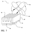
- the heat sink 80 is attached to an integrated circuit 78 such that the integrated circuit 78 and the attachment surface 84 of the heat sink are in thermal contact. Intervening layers, mechanical devices, or thermally conductive adhesives may be used to bond together the heat sink 80 and the heat-producing device 78.
- the bulk region 82 of the heat sink 80 provides a thermal mass to temporarily store thermal energy that is transferred from a heat-producing device. The thermal energy stored in the heat sink 80 is then released into the surrounding ambient by the convective surface 86.
- the module conductivity between the thermal generating device 78 and the heat sink 80 thereby allows thermal energy, as heat, to be conducted from the integrated circuit or module 78, into the heat sink 80, and then into the surrounding ambient.
- the embodiment uses air 88 as the ambient. This approach is further enhanced by adding a fan 90 to force air 88 over the convective surface 86 and to thereby increase the thermal transfer rate.
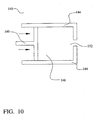
- air may be replaced with a liquid 110, such as chilled water, in a liquid cooled system 100.
- the liquid 110 is contained by a structure 112 that allows the convective surface 108 of the heat sink to receive optimal exposure to the liquid 110.
- the thermal generating device 102 may be shielded from direct contact with the liquid 110 by the containing structure 112.
- the conductive loaded, resin-based heat sink is impervious to moisture. Therefore, the heat sink 106 and 108 can be exposed to external environments like the cooling liquid 110.
- the heat sink devices 12 and 22, as shown in Figs. 1a and 1b, are fabricated of the conductor loaded, resin-based material, exhibits excellent thermal conductivity as well.
- the presence of the conductive materials homogenized within the base resin increases the thermal conductivity to a level sufficient for a heat dissipation structure.
- the conductor loaded, resin-based material provides sufficient structural stability for a reliable heat dissipation device that will perform over a large number of thermal cycles.
- the heat sink can be tailored to the expected environmental characteristics depending on the type of base resin selected.
- the conductive loaded resin-based material typically comprises a micron powder(s) of conductor particles and/or in combination of micron fiber(s) homogenized within a base resin host.
- Fig. 2 shows cross section view of an example of conductor loaded resin-based material 32 having powder of conductor particles 34 in a base resin host 30.
- the diameter D of the conductor particles 34 in the powder is between about 3 and 12 microns.
- Fig. 3 shows a cross section view of an example of conductor loaded resin-based material 36 having conductor fibers 38 in a base resin host 30.
- the conductor fibers 38 have a diameter of between about 3 and 12 microns, typically in the range of 10 microns or between about 8 and 12 microns, and a length of between about 2 and 14 millimeters.
- the conductors used for these conductor particles 34 or conductor fibers 38 can be stainless steel, nickel, copper, silver, or other suitable metals or conductive fibers, or combinations thereof. These conductor particles and or fibers are homogenized within a base resin.
- the conductive loaded resin-based materials have a resistivity between about 5 and 25 ohms per square, other resistivities can be achieved by varying the doping parameters and/or resin selection.
- the ratio of the weight of the conductor material, in this example the conductor particles 34 or conductor fibers 38, to the weight of the base resin host 30 is between about 0.20 and 0.40, and is preferably about 0.30.
- Stainless Steel Fiber of 8-11 micron in diameter and lengths of 4-6 mm with a fiber weight to base resin weight ratio of 0.30 will produce a very highly conductive parameter, efficient within any EMF spectrum.
- Fig. 4 another preferred embodiment of the present invention is illustrated where the conductive materials comprise a combination of both conductive powders 34 and micron conductive fibers 38 homogenized together within the resin base 30 during a molding process.
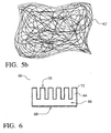
- the conductive loaded resin-based material can be formed into fibers or textiles that are then woven or webbed into a conductive fabric.
- the conductive loaded resin-based material is formed in strands that can be woven as shown.
- Fig. 5a shows a conductive fabric 42 where the fibers are woven together in a two-dimensional weave 46 and 50 of fibers or textiles.
- Fig. 5b shows a conductive fabric 42' where the fibers are formed in a webbed arrangement. In the webbed arrangement, one or more continuous strands of the conductive fiber are nested in a random fashion.
- the resulting conductive fabrics or textiles 42 see Fig. 5a, and 42', see Fig. 5b, can be made very thin, thick, rigid, flexible or in solid form(s).
- a conductive, but cloth-like, material can be formed using woven or webbed micron stainless steel fibers, or other micron conductive fibers. These woven or webbed conductive cloths could also be sandwich laminated to one or more layers of materials such as Polyester(s), Teflon(s), Kevlar(s) or any other desired resin-based material(s). This conductive fabric may then be cut into desired shapes and sizes.
- the thermal dissipation device 60 comprises a heat sink 64 fabricated with the conductive loaded, resin-based material.
- the heat sink 64 again features an attachment surface 68, a convective surface 70, and a bulk region 66 therebetween.
- a metal layer 72 is formed on the conductive loaded, resin-based heat sink 64.
- the metal layer 72 may be added to alter the thermal characteristics or the appearance of the composite heat sink.
- the metal layer 72 may be formed overlying the attachment surface 68 to alter the thermal conductivity characteristics between the heat sink 64 and the thermal generating device, not shown.
- the metal layer 72 may be formed overlying the convective surface 70 to alter the heat transfer characteristics from the heat sink 64 to the ambient medium through the fins 70.
- the metal layer 72 may be formed overlying all of the conductive loaded, resin-based heat sink 64 as shown.
- the metal layer 72 may be formed by plating or by coating. If the method of formation is metal plating, then the resin-based structural material of the conductive loaded, resin-based material is one that can be metal plated. There are very many of the polymer resins that can be plated with metal layers. For example, GE Plastics, SUPEC, VALOX, ULTEM, CYCOLAC, UGIKRAL, STYRON, CYCOLOY are a few resin-based materials that can be metal plated.
- the metal layer 72 may be formed by, for example, electroplating or physical vapor deposition.
- the resin-based structural material loaded with micron conductive powders or fibers can be formed into heat sinks in any of several ways.
- the conductive loaded resin-based materials can be molded, cut, or milled to form a heat sink.
- Fig. 9 as a first preferred method, a simplified schematic diagram of an injection molding sequence 120 for forming a heat sink 126 is shown.
- the mold comprises an upper portion 122 and a lower portion 124.
- Conductive loaded blended resin-based material 125 is injected into the mold cavity 125 through an injection opening 128 until the cavity 125 is filled, and then the inlet 128 valve 130 is closed.
- the homogenized conductive material is then cured by thermal reaction.
- the upper portion 122 and the lower portion 124 of the mold are separated and the completed conductive heat sink 126 is removed.
- a second preferred method 140 of forming the heat sink 166 from the conductive loaded resin-based material is shown.
- the heat sink is formed by extrusion.
- Conductive loaded resin-based material is placed in the hopper 148 of the extrusion unit 140.
- a piston, screw, press or other means 160 is then used to force the thermally molten or the chemically induced curing conductive loaded resin-based material through an extrusion opening 152 which shapes the thermally molten curing or chemically induced cured conductive loaded resin-based material to the desired shape.
- the conductive loaded resin-based material is then fully cured by chemical reaction or thermal reaction to a hardened or pliable state and is ready for use.
- Alternative methods of forming the heat sink device from the conductive loaded, resin-based material include over-molding, lamination, milling, stamping, or cutting. Milling and cutting are performed on conductive loaded resin-based material that is already cured into a block or sheet.
- a fifth preferred embodiment of the present invention illustrates a heat pipe 204 molded of conductive loaded resin-based material according to the present invention.
- a heat source is thermally coupled to heat spreader 212.
- a heat pipe 204 is used to conduct heat from the heat spreader 212 to a heat sink 216 where the heat is finally dissipated to the ambient.
- the heat spreader 212, heat pipe 204, and heat sink 216 may all be molded of the conductive loaded resin-based material described herein.
- the heat pipe comprises an outer conduit 220 of conductive loaded resin-based material.
- the outer conduit 220 seals in a small amount of a vaporizable liquid, such as glycol, inside 224 the pipe 204.
- a vaporizable liquid such as glycol
- heat energy from the heat source causes the vaporizable liquid to boil into the vapor state.
- the liquid molecules absorb the latent heat of vaporization from the heat source energy.
- the vaporized liquid then transports the heat energy away from the heat source and to the heat sink 216.
- thermal energy is transferred out of the vaporized liquid and into the heat sink 216 to thereby release the latent heat of vaporization and results in condensation of the liquid.
- the heat sink 216 then releases this energy to the ambient.
- the heat pipe may be size appropriately to transfer heat into the ambient without a heat sink or fin mechanism at the condensation end.
- the heat pipe 204 allows heat to be routed away from a heat source using a space efficient, small pipe. This technique facilitates the use of thermal generating devices, such as microprocessors or power supplies, in a space-confined area, such as a laptop computer. If the heat pipe 204 is oriented in a vertical manner, then the condensed liquid simply flows down to the heat source end of the heat pipe 204. In other orientations, a wicking layer 228 may be added to the conduit 220. The wicking layer 228 is used to store the small amount of vaporizable liquid in the heat pipe 204. During a thermal event, the vaporized liquid leaves the wicking layer at the heated end. At the cool end of the pipe, the vapor condenses back to liquid and is stored in the wicking 228. If used, the wicking material 228 preferably comprises a sintered powder, a grooved tube, and/or a screen mesh.
- a heat sink 304 for a group of lights 314 and, more particularly, a group of light emitting diode (LED) devices 314 is molded from the conductive loaded resin-based materials).
- the heat sink section 308, molded of conductive loaded resin-based material, also serves as one electrical terminal for the LED device(s) 314.
- the second electrical terminal 312 is also molded of conductive loaded resin-based material.
- the first terminal 308, the second terminal 312, and the heat sink fins 322 are over-molded onto the LED device(s) 314.
- the heat sink 330 is electrically isolated from the first terminal 308 and second terminal 312 by an insulating layer 326.
- the insulating layer 326 is thermally conductive.
- the first and second terminals, of conductive loaded resin-based material are first molded onto the LED anode/cathode, then the heat sink 330, of conductive loaded resin-based material, is over-molded onto the LED-terminal subassembly 308, 312, and 314.
- Either embodiment represents a large cost and weight savings when compared to metal terminal and heat sink systems.
- the heat-dissipating device is formed from a conductive loaded resin-based material to reduce manufacturing and material cost.
- the heat-dissipating device is formed from a conductive loaded resin-based material where the thermal characteristics of the heat sink can be adjusted by altering the composition of the material.
- the thermal performance of the heat-dissipating device formed from the conductive loaded resin-based material may be altered by adding a metal layer overlying the heat sink.
- Methods to fabricate a heat-dissipating device from a conductive loaded resin-based material incorporate various forms of the material.
- a method to fabricate a heat-dissipating device from a conductive loaded resin-based fabric is achieved.
- novel methods and devices of the present invention provide an effective and manufacturable alternative to the prior art.
Landscapes
- Engineering & Computer Science (AREA)
- General Engineering & Computer Science (AREA)
- Physics & Mathematics (AREA)
- Mechanical Engineering (AREA)
- Thermal Sciences (AREA)
- Manufacturing & Machinery (AREA)
- Microelectronics & Electronic Packaging (AREA)
- General Physics & Mathematics (AREA)
- Computer Hardware Design (AREA)
- Chemical & Material Sciences (AREA)
- Theoretical Computer Science (AREA)
- Dispersion Chemistry (AREA)
- Life Sciences & Earth Sciences (AREA)
- Sustainable Development (AREA)
- Cooling Or The Like Of Semiconductors Or Solid State Devices (AREA)
- Cooling Or The Like Of Electrical Apparatus (AREA)
- Injection Moulding Of Plastics Or The Like (AREA)
- Extrusion Moulding Of Plastics Or The Like (AREA)
Applications Claiming Priority (6)
| Application Number | Priority Date | Filing Date | Title |
|---|---|---|---|
| US46207203P | 2003-04-14 | 2003-04-14 | |
| US462072P | 2003-04-14 | ||
| US47877503P | 2003-06-16 | 2003-06-16 | |
| US478775P | 2003-06-16 | ||
| US10/807,036 US7027304B2 (en) | 2001-02-15 | 2004-03-23 | Low cost thermal management device or heat sink manufactured from conductive loaded resin-based materials |
| US807036 | 2004-03-23 |
Publications (2)
| Publication Number | Publication Date |
|---|---|
| EP1469513A2 true EP1469513A2 (fr) | 2004-10-20 |
| EP1469513A3 EP1469513A3 (fr) | 2004-12-15 |
Family
ID=32913043
Family Applications (1)
| Application Number | Title | Priority Date | Filing Date |
|---|---|---|---|
| EP04368030A Withdrawn EP1469513A3 (fr) | 2003-04-14 | 2004-04-14 | Dispositif de traitement thermique ou dissipateur de chaleur à faible coût fabriqué à partir de matériaux conducteurs à base de résine |
Country Status (6)
| Country | Link |
|---|---|
| US (1) | US7027304B2 (fr) |
| EP (1) | EP1469513A3 (fr) |
| JP (1) | JP2004349685A (fr) |
| KR (1) | KR20040089590A (fr) |
| CN (1) | CN1551339A (fr) |
| CA (1) | CA2464280A1 (fr) |
Cited By (9)
| Publication number | Priority date | Publication date | Assignee | Title |
|---|---|---|---|---|
| WO2006128826A1 (fr) * | 2005-06-01 | 2006-12-07 | Siemens Aktiengesellschaft | Appareil electronique pourvu d'une resistance |
| US7427807B2 (en) | 2005-02-18 | 2008-09-23 | Mitac Technology Corp. | Chip heat dissipation structure and manufacturing method |
| US7504148B2 (en) | 2005-03-03 | 2009-03-17 | Mitac Technology Corp | Printed circuit board structure and manufacturing method thereof |
| DE102009022877A1 (de) * | 2009-04-29 | 2010-11-11 | Electrovac Ag | Gekühlte elektrische Baueinheit |
| WO2011123267A1 (fr) * | 2010-04-02 | 2011-10-06 | GE Lighting Solutions, LLC | Dissipateurs thermiques légers et lampes à del utilisant ces derniers |
| WO2013173067A1 (fr) * | 2012-05-18 | 2013-11-21 | 3M Innovative Properties Company | Appareil et procédé de moulage par injection |
| EP2871674A4 (fr) * | 2012-07-07 | 2016-02-17 | Dexerials Corp | Feuille thermo-conductrice |
| US10340424B2 (en) | 2002-08-30 | 2019-07-02 | GE Lighting Solutions, LLC | Light emitting diode component |
| TWI901127B (zh) * | 2024-05-17 | 2025-10-11 | 國立高雄科技大學 | 散熱板結構及其製造方法 |
Families Citing this family (77)
| Publication number | Priority date | Publication date | Assignee | Title |
|---|---|---|---|---|
| US20040227688A1 (en) * | 2001-02-15 | 2004-11-18 | Integral Technologies, Inc. | Metal plating of conductive loaded resin-based materials for low cost manufacturing of conductive articles |
| US20050200329A1 (en) * | 2001-02-15 | 2005-09-15 | Integral Technologies, Inc. | Low cost charger connections manufactured from conductive loaded resin-based material |
| US6935022B2 (en) * | 2001-08-28 | 2005-08-30 | Advanced Materials Technologies Pte, Ltd. | Advanced microelectronic heat dissipation package and method for its manufacture |
| US8309112B2 (en) * | 2003-12-24 | 2012-11-13 | Advanced Cardiovascular Systems, Inc. | Coatings for implantable medical devices comprising hydrophilic substances and methods for fabricating the same |
| US20050243521A1 (en) * | 2004-04-30 | 2005-11-03 | Michael Li | Aligning socket load plates to integral heat spreaders |
| US20060070720A1 (en) * | 2004-09-17 | 2006-04-06 | Capp Joseph P | Heat riser |
| US11320129B1 (en) | 2004-10-05 | 2022-05-03 | Steven Michael Colby | LED bulb including pulse generator and/or AC/DC converter |
| US9874332B1 (en) * | 2013-01-15 | 2018-01-23 | Steven Michael Colby | Bulb including removable cover |
| KR100638047B1 (ko) * | 2004-10-15 | 2006-10-23 | 엘지전자 주식회사 | 백라이트 유닛을 갖는 액정 디스플레이 |
| DE102005063433B4 (de) * | 2004-10-29 | 2009-11-26 | Lg Display Co., Ltd. | Hintergrundbeleuchtungseinheit und Flüssigkristall-Anzeigevorrichtung |
| US20060196640A1 (en) * | 2004-12-01 | 2006-09-07 | Convergence Technologies Limited | Vapor chamber with boiling-enhanced multi-wick structure |
| WO2006088065A1 (fr) * | 2005-02-16 | 2006-08-24 | Hitachi Metals, Ltd. | Element de dissipation thermique et son procede de fabrication |
| US20070200133A1 (en) * | 2005-04-01 | 2007-08-30 | Akira Hashimoto | Led assembly and manufacturing method |
| CN100566527C (zh) * | 2005-04-07 | 2009-12-02 | 神基科技股份有限公司 | 黏着材料与其制作方法 |
| TWM278828U (en) * | 2005-05-11 | 2005-10-21 | Shiu Yung Yuan | LED planar light source module |
| TWI275342B (en) * | 2005-07-29 | 2007-03-01 | Delta Electronics Inc | Method for increasing heat-dissipating efficiency of a heat-dissipating device and the structure thereof |
| JP4830436B2 (ja) * | 2005-10-03 | 2011-12-07 | 株式会社日立製作所 | ディスプレイ装置 |
| US7365988B2 (en) * | 2005-11-04 | 2008-04-29 | Graftech International Holdings Inc. | Cycling LED heat spreader |
| KR100732320B1 (ko) | 2006-01-24 | 2007-06-25 | 주식회사 케이씨티 | 도전성 수지 조성물과 그 성형품의 제조방법 |
| US7974096B2 (en) * | 2006-08-17 | 2011-07-05 | Ati Technologies Ulc | Three-dimensional thermal spreading in an air-cooled thermal device |
| US20090086491A1 (en) | 2007-09-28 | 2009-04-02 | Ruud Lighting, Inc. | Aerodynamic LED Floodlight Fixture |
| US7952262B2 (en) | 2006-09-30 | 2011-05-31 | Ruud Lighting, Inc. | Modular LED unit incorporating interconnected heat sinks configured to mount and hold adjacent LED modules |
| US7686469B2 (en) | 2006-09-30 | 2010-03-30 | Ruud Lighting, Inc. | LED lighting fixture |
| US9243794B2 (en) | 2006-09-30 | 2016-01-26 | Cree, Inc. | LED light fixture with fluid flow to and from the heat sink |
| US9028087B2 (en) | 2006-09-30 | 2015-05-12 | Cree, Inc. | LED light fixture |
| US7784972B2 (en) * | 2006-12-22 | 2010-08-31 | Nuventix, Inc. | Thermal management system for LED array |
| EP2109887B1 (fr) * | 2007-02-02 | 2018-06-27 | DSM IP Assets B.V. | Assemblage de transport thermique |
| US8356410B2 (en) * | 2007-06-13 | 2013-01-22 | The Boeing Company | Heat pipe dissipating system and method |
| JP4631877B2 (ja) * | 2007-07-02 | 2011-02-16 | スターライト工業株式会社 | 樹脂製ヒートシンク |
| US7843695B2 (en) * | 2007-07-20 | 2010-11-30 | Honeywell International Inc. | Apparatus and method for thermal management using vapor chamber |
| US20090145581A1 (en) * | 2007-12-11 | 2009-06-11 | Paul Hoffman | Non-linear fin heat sink |
| JP2009188720A (ja) * | 2008-02-06 | 2009-08-20 | Panasonic Corp | 固体撮像装置およびその製造方法 |
| CN101977976B (zh) * | 2008-03-20 | 2014-08-27 | 帝斯曼知识产权资产管理有限公司 | 导热塑料材料的热沉 |
| TWM343111U (en) * | 2008-04-18 | 2008-10-21 | Genius Electronic Optical Co Ltd | Light base of high-wattage LED street light |
| KR101022954B1 (ko) * | 2008-05-30 | 2011-03-16 | 삼성전기주식회사 | 방열핀과 이 방열핀을 포함하는 패키지 기판 및 그제조방법 |
| US20100014251A1 (en) * | 2008-07-15 | 2010-01-21 | Advanced Micro Devices, Inc. | Multidimensional Thermal Management Device for an Integrated Circuit Chip |
| JP2010102978A (ja) * | 2008-10-24 | 2010-05-06 | Koito Mfg Co Ltd | 車両用灯具 |
| US8192048B2 (en) * | 2009-04-22 | 2012-06-05 | 3M Innovative Properties Company | Lighting assemblies and systems |
| JP5683799B2 (ja) * | 2009-09-14 | 2015-03-11 | スターライト工業株式会社 | 自動車用led用ヒートシンク |
| US8593040B2 (en) | 2009-10-02 | 2013-11-26 | Ge Lighting Solutions Llc | LED lamp with surface area enhancing fins |
| US8668356B2 (en) * | 2010-04-02 | 2014-03-11 | GE Lighting Solutions, LLC | Lightweight heat sinks and LED lamps employing same |
| TW201204991A (en) * | 2010-07-30 | 2012-02-01 | Zhen-Meng Lin | Molding method and structure of LED lamp heat sink with micro/nano metal and graphite |
| CN102345842A (zh) * | 2010-08-06 | 2012-02-08 | 林振孟 | 具微奈米金属和石墨的led灯具散热器结构 |
| CN203594979U (zh) * | 2011-01-19 | 2014-05-14 | 格拉弗技术国际控股有限公司 | 电灯灯泡 |
| JP5738652B2 (ja) * | 2011-03-30 | 2015-06-24 | 日東電工株式会社 | 熱伝導性シートの製造方法および熱伝導性シート |
| US20120299173A1 (en) * | 2011-05-26 | 2012-11-29 | Futurewei Technologies, Inc. | Thermally Enhanced Stacked Package and Method |
| US8723205B2 (en) | 2011-08-30 | 2014-05-13 | Abl Ip Holding Llc | Phosphor incorporated in a thermal conductivity and phase transition heat transfer mechanism |
| US8759843B2 (en) | 2011-08-30 | 2014-06-24 | Abl Ip Holding Llc | Optical/electrical transducer using semiconductor nanowire wicking structure in a thermal conductivity and phase transition heat transfer mechanism |
| US8710526B2 (en) | 2011-08-30 | 2014-04-29 | Abl Ip Holding Llc | Thermal conductivity and phase transition heat transfer mechanism including optical element to be cooled by heat transfer of the mechanism |
| US9500355B2 (en) | 2012-05-04 | 2016-11-22 | GE Lighting Solutions, LLC | Lamp with light emitting elements surrounding active cooling device |
| CN102651961B (zh) * | 2012-05-29 | 2016-02-03 | 安顿雷纳(上海)纤维材料科技有限公司 | 一种导热散热界面材料及其制造方法 |
| EP2713132A1 (fr) * | 2012-09-26 | 2014-04-02 | Alcatel Lucent | Appareil de transfert de chaleur par évaporation |
| KR101543888B1 (ko) * | 2013-12-20 | 2015-08-11 | 주식회사 포스코 | 방열성이 우수한 금속 봉지재, 그 제조방법 및 상기 금속 봉지재로 봉지된 유연전자소자 |
| JP6242296B2 (ja) * | 2014-05-30 | 2017-12-06 | ダイキョーニシカワ株式会社 | 電池モジュール |
| KR101648437B1 (ko) * | 2014-06-02 | 2016-08-17 | 주식회사 티앤머티리얼스 | 탄소계 금속기지 복합체를 이용한 핀 타입 방열 기판 제조방법 |
| CN105742252B (zh) | 2014-12-09 | 2019-05-07 | 台达电子工业股份有限公司 | 一种功率模块及其制造方法 |
| FR3030911B1 (fr) * | 2014-12-17 | 2018-05-18 | Thales | Source monolithique d'antenne pour application spatiale |
| CN105114920A (zh) * | 2015-09-17 | 2015-12-02 | 张逸兴 | 一种利用导热材料线材编织物换热的装置 |
| GB2543790A (en) * | 2015-10-28 | 2017-05-03 | Sustainable Engine Systems Ltd | Pin fin heat exchanger |
| US11283186B2 (en) * | 2016-03-25 | 2022-03-22 | Commscope Technologies Llc | Antennas having lenses formed of lightweight dielectric materials and related dielectric materials |
| US11431100B2 (en) | 2016-03-25 | 2022-08-30 | Commscope Technologies Llc | Antennas having lenses formed of lightweight dielectric materials and related dielectric materials |
| WO2017184148A1 (fr) * | 2016-04-21 | 2017-10-26 | Hewlett-Packard Development Company, L.P. | Nanotube de carbone et mèche de caloduc à base d'aérogel de graphène |
| JP2018037520A (ja) * | 2016-08-31 | 2018-03-08 | 富士通株式会社 | 半導体装置、電子装置、半導体装置の製造方法及び電子装置の製造方法 |
| US10543036B2 (en) * | 2017-06-13 | 2020-01-28 | Covidien Lp | Systems and methods of cooling surgical instruments |
| US11527835B2 (en) | 2017-09-15 | 2022-12-13 | Commscope Technologies Llc | Methods of preparing a composite dielectric material |
| US10876606B2 (en) * | 2018-03-13 | 2020-12-29 | Gates Corporation | Orbital tensioner |
| CN108844395A (zh) * | 2018-04-23 | 2018-11-20 | 深圳市邦德威尔新型材料有限公司 | 一种散热部件及其制作工艺 |
| CN112188953A (zh) * | 2018-05-25 | 2021-01-05 | 昕诺飞控股有限公司 | 由fdm打印的导热复合物及有效散热的策略 |
| TW202100626A (zh) * | 2019-01-29 | 2021-01-01 | 日商松下知識產權經營股份有限公司 | 衝擊吸收積層體、顯示裝置 |
| JP7164023B2 (ja) * | 2019-03-22 | 2022-11-01 | 昭和電工マテリアルズ株式会社 | 冷却構造体 |
| US11333223B2 (en) | 2019-08-06 | 2022-05-17 | Gates Corporation | Orbital tensioner |
| CN110791257A (zh) * | 2019-10-08 | 2020-02-14 | 鞍钢股份有限公司 | 一种定向传热相变储热材料的制备方法及装置 |
| USD926077S1 (en) * | 2019-10-10 | 2021-07-27 | Calyxt, Inc. | Plant separator |
| CN112553547B (zh) * | 2020-12-07 | 2022-01-18 | 深圳市天士力神通本草技术开发有限公司 | 一种高导热金属基碳纤维发热体材料的制备方法 |
| DE102022202730B4 (de) * | 2022-03-21 | 2024-02-15 | Siemens Healthcare Gmbh | Röntgenhochspannungsgenerator mit einem oszillierendem Wärmerohr |
| JP7719120B2 (ja) * | 2023-05-10 | 2025-08-05 | 矢崎総業株式会社 | 車両用電源ボックス |
| DE102023115440A1 (de) * | 2023-06-14 | 2024-12-19 | Relineeurope Gmbh | Aushärtevorrichtung mit lüfter und ablenkelement |
Family Cites Families (36)
| Publication number | Priority date | Publication date | Assignee | Title |
|---|---|---|---|---|
| US3936686A (en) * | 1973-05-07 | 1976-02-03 | Moore Donald W | Reflector lamp cooling and containing assemblies |
| US4838346A (en) * | 1988-08-29 | 1989-06-13 | The United States Of America As Represented By The Administrator Of The National Aeronautics And Space Administration | Reusable high-temperature heat pipes and heat pipe panels |
| US5060114A (en) * | 1990-06-06 | 1991-10-22 | Zenith Electronics Corporation | Conformable pad with thermally conductive additive for heat dissipation |
| JPH04291948A (ja) | 1991-03-20 | 1992-10-16 | Fujitsu Ltd | 半導体装置及びその製造方法及び放熱フィン |
| US5371404A (en) * | 1993-02-04 | 1994-12-06 | Motorola, Inc. | Thermally conductive integrated circuit package with radio frequency shielding |
| AU7841594A (en) | 1993-09-30 | 1995-04-18 | Universal Electronics Inc. | Led assembly with enhanced power output |
| US5649593A (en) * | 1996-01-17 | 1997-07-22 | Kitagawa Industries Co., Ltd. | Radiator member |
| US5738936A (en) * | 1996-06-27 | 1998-04-14 | W. L. Gore & Associates, Inc. | Thermally conductive polytetrafluoroethylene article |
| US5695847A (en) * | 1996-07-10 | 1997-12-09 | Browne; James M. | Thermally conductive joining film |
| US5857767A (en) * | 1996-09-23 | 1999-01-12 | Relume Corporation | Thermal management system for L.E.D. arrays |
| US5781412A (en) * | 1996-11-22 | 1998-07-14 | Parker-Hannifin Corporation | Conductive cooling of a heat-generating electronic component using a cured-in-place, thermally-conductive interlayer having a filler of controlled particle size |
| JP2001503471A (ja) * | 1997-02-07 | 2001-03-13 | ロックタイト コーポレーション | 伝導性樹脂組成物 |
| DE19805930A1 (de) * | 1997-02-13 | 1998-08-20 | Furukawa Electric Co Ltd | Kühlvorrichtung |
| US5986885A (en) * | 1997-04-08 | 1999-11-16 | Integrated Device Technology, Inc. | Semiconductor package with internal heatsink and assembly method |
| CA2255441C (fr) * | 1997-12-08 | 2003-08-05 | Hiroki Sekiya | Boitier pour dispositif d'alimentation a semiconducteurs et methode d'assemblage connexe |
| US6107216A (en) * | 1997-12-12 | 2000-08-22 | Raytheon Company | Bonded structure with high-conductivity bonding element |
| JP2000273196A (ja) * | 1999-03-24 | 2000-10-03 | Polymatech Co Ltd | 熱伝導性樹脂基板および半導体パッケージ |
| GB2358243B (en) * | 1999-11-24 | 2004-03-31 | 3Com Corp | Thermally conductive moulded heat sink |
| US6397941B1 (en) * | 1999-12-01 | 2002-06-04 | Cool Options, Inc. | Net-shape molded heat exchanger |
| JP2001217359A (ja) * | 2000-01-31 | 2001-08-10 | Shinko Electric Ind Co Ltd | 放熱用フィン及びその製造方法並びに半導体装置 |
| US6949822B2 (en) | 2000-03-17 | 2005-09-27 | International Rectifier Corporation | Semiconductor multichip module package with improved thermal performance; reduced size and improved moisture resistance |
| RU2206502C2 (ru) * | 2000-11-21 | 2003-06-20 | Акционерное общество закрытого типа "Карбид" | Композиционный материал |
| NL1016779C2 (nl) * | 2000-12-02 | 2002-06-04 | Cornelis Johannes Maria V Rijn | Matrijs, werkwijze voor het vervaardigen van precisieproducten met behulp van een matrijs, alsmede precisieproducten, in het bijzonder microzeven en membraanfilters, vervaardigd met een dergelijke matrijs. |
| KR20020045694A (ko) | 2000-12-09 | 2002-06-20 | 이택렬 | 광 반도체 소자 및 그 제조방법 |
| US6741221B2 (en) | 2001-02-15 | 2004-05-25 | Integral Technologies, Inc. | Low cost antennas using conductive plastics or conductive composites |
| KR100419611B1 (ko) | 2001-05-24 | 2004-02-25 | 삼성전기주식회사 | 발광다이오드 및 이를 이용한 발광장치와 그 제조방법 |
| JP4714371B2 (ja) | 2001-06-06 | 2011-06-29 | ポリマテック株式会社 | 熱伝導性成形体及びその製造方法 |
| GB0116700D0 (en) | 2001-07-09 | 2001-08-29 | Sayers Michael P | Electrically conductive composition |
| WO2003017365A2 (fr) | 2001-08-17 | 2003-02-27 | Honeywell International Inc. | Dispositifs de transfert thermique |
| JP2003100968A (ja) * | 2001-09-21 | 2003-04-04 | Toyota Industries Corp | 放熱材及びその製造方法 |
| US6565772B2 (en) * | 2001-09-25 | 2003-05-20 | Midwest Thermal Spray | Conductive resin composition |
| US6822018B2 (en) * | 2002-02-15 | 2004-11-23 | Delphi Technologies, Inc. | Thermally-conductive electrically-insulating polymer-base material |
| US20030183379A1 (en) | 2002-03-29 | 2003-10-02 | Krassowski Daniel W. | Optimized heat sink using high thermal conducting base and low thermal conducting fins |
| US6919504B2 (en) * | 2002-12-19 | 2005-07-19 | 3M Innovative Properties Company | Flexible heat sink |
| US7252877B2 (en) * | 2003-02-04 | 2007-08-07 | Intel Corporation | Polymer matrices for polymer solder hybrid materials |
| US20040264195A1 (en) * | 2003-06-25 | 2004-12-30 | Chia-Fu Chang | Led light source having a heat sink |
-
2004
- 2004-03-23 US US10/807,036 patent/US7027304B2/en not_active Expired - Fee Related
- 2004-04-13 CA CA002464280A patent/CA2464280A1/fr not_active Abandoned
- 2004-04-14 KR KR1020040025732A patent/KR20040089590A/ko not_active Ceased
- 2004-04-14 EP EP04368030A patent/EP1469513A3/fr not_active Withdrawn
- 2004-04-14 JP JP2004119383A patent/JP2004349685A/ja active Pending
- 2004-04-14 CN CNA2004100387966A patent/CN1551339A/zh active Pending
Cited By (15)
| Publication number | Priority date | Publication date | Assignee | Title |
|---|---|---|---|---|
| US10340424B2 (en) | 2002-08-30 | 2019-07-02 | GE Lighting Solutions, LLC | Light emitting diode component |
| US7427807B2 (en) | 2005-02-18 | 2008-09-23 | Mitac Technology Corp. | Chip heat dissipation structure and manufacturing method |
| US7504148B2 (en) | 2005-03-03 | 2009-03-17 | Mitac Technology Corp | Printed circuit board structure and manufacturing method thereof |
| WO2006128826A1 (fr) * | 2005-06-01 | 2006-12-07 | Siemens Aktiengesellschaft | Appareil electronique pourvu d'une resistance |
| DE102009022877A1 (de) * | 2009-04-29 | 2010-11-11 | Electrovac Ag | Gekühlte elektrische Baueinheit |
| DE102009022877B4 (de) * | 2009-04-29 | 2014-12-24 | Rogers Germany Gmbh | Gekühlte elektrische Baueinheit |
| US10240772B2 (en) | 2010-04-02 | 2019-03-26 | GE Lighting Solutions, LLC | Lightweight heat sinks and LED lamps employing same |
| WO2011123267A1 (fr) * | 2010-04-02 | 2011-10-06 | GE Lighting Solutions, LLC | Dissipateurs thermiques légers et lampes à del utilisant ces derniers |
| AU2011233568B2 (en) * | 2010-04-02 | 2015-11-12 | GE Lighting Solutions, LLC | Lightweight heat sinks and LED lamps employing same |
| US8663537B2 (en) | 2012-05-18 | 2014-03-04 | 3M Innovative Properties Company | Injection molding apparatus and method |
| WO2013173067A1 (fr) * | 2012-05-18 | 2013-11-21 | 3M Innovative Properties Company | Appareil et procédé de moulage par injection |
| US10106672B2 (en) | 2012-07-07 | 2018-10-23 | Dexerials Corporation | Heat conductive sheet |
| EP2871674A4 (fr) * | 2012-07-07 | 2016-02-17 | Dexerials Corp | Feuille thermo-conductrice |
| EP3790044A1 (fr) * | 2012-07-07 | 2021-03-10 | Dexerials Corporation | Feuille de conduction de chaleur |
| TWI901127B (zh) * | 2024-05-17 | 2025-10-11 | 國立高雄科技大學 | 散熱板結構及其製造方法 |
Also Published As
| Publication number | Publication date |
|---|---|
| US7027304B2 (en) | 2006-04-11 |
| EP1469513A3 (fr) | 2004-12-15 |
| CN1551339A (zh) | 2004-12-01 |
| US20040174651A1 (en) | 2004-09-09 |
| JP2004349685A (ja) | 2004-12-09 |
| CA2464280A1 (fr) | 2004-10-14 |
| KR20040089590A (ko) | 2004-10-21 |
Similar Documents
| Publication | Publication Date | Title |
|---|---|---|
| US7027304B2 (en) | Low cost thermal management device or heat sink manufactured from conductive loaded resin-based materials | |
| JP5568289B2 (ja) | 放熱部品及びその製造方法 | |
| CN101601130B (zh) | 热传输组件 | |
| JP5144635B2 (ja) | 電子装置の製造方法 | |
| US20070053166A1 (en) | Heat dissipation device and composite material with high thermal conductivity | |
| US7268479B2 (en) | Low cost lighting circuits manufactured from conductive loaded resin-based materials | |
| KR20040005940A (ko) | 열관리 물질, 장치 및 방법 | |
| JP2017220539A (ja) | ヒートシンク及び冷却器 | |
| TWI603441B (zh) | 功率模組及其製造方法 | |
| EP1469707A2 (fr) | Procédé de fabrication d'un circuit d'éclairage avec une composition à base de resine conductrice | |
| CN112382620A (zh) | 热传导结构及其制造方法、移动装置 | |
| TWM337227U (en) | Circuit board having heat dissipating function | |
| JP4443746B2 (ja) | 異方性伝熱シートの製造方法 | |
| WO2003017365A2 (fr) | Dispositifs de transfert thermique | |
| CN101017067A (zh) | 散热板及其制备方法 | |
| US7645641B2 (en) | Cooling device with a preformed compliant interface | |
| CN207443315U (zh) | 一种带有金属嵌件的通信设备用轻量化塑料散热器 | |
| JPH1168263A (ja) | 電子回路基板 | |
| CN207305063U (zh) | 热管与pcb板配合结构 | |
| CN206686497U (zh) | 一种基于金属相变导热导电的散热装置 | |
| US20060000590A1 (en) | Low cost vehicle heat exchange devices manufactured from conductive loaded resin-based materials | |
| JP7129316B2 (ja) | 沸騰伝熱部材および沸騰冷却装置 | |
| US20050274013A1 (en) | Low cost vehicle heat exchange devices manufactured from conductive loaded resin-based materials | |
| TW201146097A (en) | Heat dissipating plate | |
| US7002234B2 (en) | Low cost capacitors manufactured from conductive loaded resin-based materials |
Legal Events
| Date | Code | Title | Description |
|---|---|---|---|
| PUAI | Public reference made under article 153(3) epc to a published international application that has entered the european phase |
Free format text: ORIGINAL CODE: 0009012 |
|
| AK | Designated contracting states |
Kind code of ref document: A2 Designated state(s): AT BE BG CH CY CZ DE DK EE ES FI FR GB GR HU IE IT LI LU MC NL PL PT RO SE SI SK TR |
|
| AX | Request for extension of the european patent |
Extension state: AL HR LT LV MK |
|
| PUAL | Search report despatched |
Free format text: ORIGINAL CODE: 0009013 |
|
| RIC1 | Information provided on ipc code assigned before grant |
Ipc: 7F 21V 29/00 B Ipc: 7H 01L 33/00 B Ipc: 7H 01L 23/473 B Ipc: 7H 01L 23/467 B Ipc: 7H 01L 23/367 B Ipc: 7H 01L 23/427 B Ipc: 7H 01L 23/373 A |
|
| AK | Designated contracting states |
Kind code of ref document: A3 Designated state(s): AT BE BG CH CY CZ DE DK EE ES FI FR GB GR HU IE IT LI LU MC NL PL PT RO SE SI SK TR |
|
| AX | Request for extension of the european patent |
Extension state: AL HR LT LV MK |
|
| 17P | Request for examination filed |
Effective date: 20050615 |
|
| AKX | Designation fees paid |
Designated state(s): AT BE BG CH CY CZ DE DK EE ES FI FR GB GR HU IE IT LI LU MC NL PL PT RO SE SI SK TR |
|
| STAA | Information on the status of an ep patent application or granted ep patent |
Free format text: STATUS: THE APPLICATION IS DEEMED TO BE WITHDRAWN |
|
| 18D | Application deemed to be withdrawn |
Effective date: 20060419 |