EP1470065B1 - Integriertes fördersystem zur beförderung von lasten, insbesondere fahrzeugen, entlang einer fertigungsstrasse - Google Patents
Integriertes fördersystem zur beförderung von lasten, insbesondere fahrzeugen, entlang einer fertigungsstrasse Download PDFInfo
- Publication number
- EP1470065B1 EP1470065B1 EP02805877A EP02805877A EP1470065B1 EP 1470065 B1 EP1470065 B1 EP 1470065B1 EP 02805877 A EP02805877 A EP 02805877A EP 02805877 A EP02805877 A EP 02805877A EP 1470065 B1 EP1470065 B1 EP 1470065B1
- Authority
- EP
- European Patent Office
- Prior art keywords
- module
- belt
- powered
- trucks
- rails
- Prior art date
- Legal status (The legal status is an assumption and is not a legal conclusion. Google has not performed a legal analysis and makes no representation as to the accuracy of the status listed.)
- Expired - Lifetime
Links
- 238000004519 manufacturing process Methods 0.000 title description 9
- 238000011144 upstream manufacturing Methods 0.000 claims description 17
- 125000006850 spacer group Chemical group 0.000 claims description 5
- 239000003831 antifriction material Substances 0.000 claims description 3
- 230000006835 compression Effects 0.000 claims 1
- 238000007906 compression Methods 0.000 claims 1
- 230000015572 biosynthetic process Effects 0.000 description 2
- 239000000463 material Substances 0.000 description 2
- 238000000034 method Methods 0.000 description 2
- 229910000831 Steel Inorganic materials 0.000 description 1
- 230000005540 biological transmission Effects 0.000 description 1
- 229910001234 light alloy Inorganic materials 0.000 description 1
- 239000002184 metal Substances 0.000 description 1
- 239000010959 steel Substances 0.000 description 1
- 230000036967 uncompetitive effect Effects 0.000 description 1
Images


Classifications
-
- B—PERFORMING OPERATIONS; TRANSPORTING
- B62—LAND VEHICLES FOR TRAVELLING OTHERWISE THAN ON RAILS
- B62D—MOTOR VEHICLES; TRAILERS
- B62D65/00—Designing, manufacturing, e.g. assembling, facilitating disassembly, or structurally modifying motor vehicles or trailers, not otherwise provided for
- B62D65/02—Joining sub-units or components to, or positioning sub-units or components with respect to, body shell or other sub-units or components
- B62D65/18—Transportation, conveyor or haulage systems specially adapted for motor vehicle or trailer assembly lines
-
- B—PERFORMING OPERATIONS; TRANSPORTING
- B65—CONVEYING; PACKING; STORING; HANDLING THIN OR FILAMENTARY MATERIAL
- B65G—TRANSPORT OR STORAGE DEVICES, e.g. CONVEYORS FOR LOADING OR TIPPING, SHOP CONVEYOR SYSTEMS OR PNEUMATIC TUBE CONVEYORS
- B65G35/00—Mechanical conveyors not otherwise provided for
- B65G35/08—Mechanical conveyors not otherwise provided for comprising trains of unconnected load-carriers, e.g. belt sections, movable in a path, e.g. a closed path, adapted to contact each other and to be propelled by means arranged to engage each load-carrier in turn
-
- B—PERFORMING OPERATIONS; TRANSPORTING
- B65—CONVEYING; PACKING; STORING; HANDLING THIN OR FILAMENTARY MATERIAL
- B65G—TRANSPORT OR STORAGE DEVICES, e.g. CONVEYORS FOR LOADING OR TIPPING, SHOP CONVEYOR SYSTEMS OR PNEUMATIC TUBE CONVEYORS
- B65G2201/00—Indexing codes relating to handling devices, e.g. conveyors, characterised by the type of product or load being conveyed or handled
- B65G2201/02—Articles
- B65G2201/0294—Vehicle bodies
Definitions
- the present invention relates to an integrated conveyor system for moving loads, in particular vehicles, along an assembly line.
- European Patent n. 0873271 filed by the present Applicant, describes a modular conveyor (known commercially as TTS) comprising a number of modules powered by independent motors, and each of which comprises a contoured structure (e.g. extruded, but which can also be formed using steel sections or other methods) defining a pair of rails, and a powered belt stretched inside the transverse space between the pair of rails, over or under the rails.
- the modules are arranged with the pairs of rails end to end to form a substantially continuous support and guide structure defining an endless path, and along which run a number of trucks, which engage the rails with respective rollers, and each of which has at least one pair of grip pads for engaging the belt of each module with the aid of push means.
- the trucks are thus moved selectively by the belt of each module along the rails in a predetermined direction; and transit from one module to the next is made possible by the distance between the pads of each truck being greater than the distance between the belts of two adjacent modules, so that, until the downstream pad of a truck traveling between two modules engages the downstream module, the upstream pad of the same truck still engages the belt of the module the truck is leaving, so that the truck is "pushed” onto the downstream module.
- the downstream pad engages the belt of the downstream module
- the truck is "pulled” by the downstream module belt, thus enabling the upstream pad to leave the upstream module.
- Conveyors of the above type have been enormously successful commercially, in that the modules can be floor-mounted or suspended from an overhead structure, and provide for moving the trucks horizontally as well as up and down inclines; curved portions can be formed using modules of appropriate length and shape; and the same trucks can be equipped with floor conveyor pallets, or with attachments, possibly movable vertically, for overhead loads.
- the TTS conveyor is currently unsuitable, in terms of cost, for vehicle assembly lines involving a high degree of precision, and is mainly used for other types of transportation and/or as assembly line return lines.
- Assembly lines are therefore equipped with conventional conveyors, in which a number of nonpowered trucks or platforms are accumulated to form a "train", which is moved along the assembly line by pushing the last upstream platform in the train (here and in the following description, "upstream” and “downstream” are used with reference to the traveling direction of the movable conveying members, be they trucks or platforms) by means of a push station defined by a number of powered rollers, which frictionally and laterally engage the longitudinal edges of the last upstream, i.e. tail, platform in the train; and the train of trucks/platforms is held together, with the trucks/platforms contacting one another, by a downstream braking station acting on the lead truck/platform in the train.
- a push station defined by a number of powered rollers, which frictionally and laterally engage the longitudinal edges of the last upstream, i.e. tail, platform in the train
- the train of trucks/platforms is held together, with the trucks/platforms contacting one another, by a downstream braking station acting on the lead truck
- the conveyor system resulting from integrating the above conveyor system and the TTS conveyor has several drawbacks, such as relatively high manufacturing cost, excessive rail size, and no standardization. Moreover, the number of trucks/platforms in the "train”, and hence the length of the production line, are restricted by the horizontal force the push station is capable of producing.
- an integrated conveyor system comprising a number of trucks, and a number of independent modules, each comprising a pair of rails, and a powered belt stretched inside the transverse space defined between the pair of rails; the modules being arranged with the pairs of rails end to end to form a substantially continuous support and guide structure for said trucks, which run along said pairs of rails, and each have at least one pair of grip pads, which, with the aid of push means, selectively engage, and are moved along the rails in a predetermined direction by, the powered belts of said modules; the pads of each truck being located such a distance apart that, when a truck leaves a first module to engage a second module adjacent to the first, at least one pad of the truck still cooperates with the belt of at least one of said first and second modules; characterized by also comprising:
- the system also comprises a brake module having a nonpowered idle belt, and located at a second end of the work line opposite the first end.
- Both the production line and the return line are therefore formed using standard TTS modules, thus reducing the size and cost of the production line rails and the cost of the conveyor system as a whole, by using standard, mass produced components.
- no sophisticated, high-cost electronic control system is required to synchronize the speed of the motors of the TTS modules forming the production line.
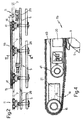
- number 1 indicates as a whole an integrated conveyor system comprising a number of independent modules 11, each comprising ( Figure 3) a pair of rails 2, 3, and a powered belt 4 stretched inside the transverse space defined between the pair of rails 2, 3.
- Modules 11 are arranged with the pairs of rails 2, 3 end to end to form a support and guide structure 7, which is substantially continuous (except for the small assembly gap between adjacent modules) and forms an endless path of any shape (Figure 1) for a number of trucks 5 which run along pairs of rails 2, 3.
- Each truck 5 comprises a number of wheels or rollers 49 idly engaging pairs of rails 2, 3 to guide the truck both transversely and vertically; and at least one pair of grip pads 8 and 9, which, with the aid of push means 10 (Figure 3) defined, for example, by helical springs, selectively engage powered belts 4 of modules 11, and are moved by powered belts 4 of modules 11 in a predetermined direction depending on the traveling direction of belts 4.
- the powered belt 4 of each module 11 is supported over and connected integrally to rails 2, 3 by a supporting structure 14 ( Figure 3) made, like rails 2, 3, preferably, though not necessarily, from extruded metal sections, e.g. of light alloy.
- each structure 14 supports a belt 4 stretched, to form an endless loop comprising two straight branches, between a pair of rotary pulleys 15, 16 ( Figures 2 and 4), which are thus carried integrally by respective module 11.
- Belts 4 are preferably, though not necessarily, double-toothed belts ( Figures 4 and 5), i.e. having a number of transverse teeth 18 formed on an outer face (facing trucks 5 in use) of the bottom branch (adjacent to trucks 5 in use) defined by belt 4, and a number of transverse teeth 19 formed on an inner face (facing away from trucks 5) of said bottom branch of belt 4.
- the invention obviously also extends to the use of flat belts having no teeth on one or both faces.
- Pads 8, 9 of each truck 5 are preferably, though not necessarily, toothed pads for engaging the outer face of the bottom branch of each belt 4.
- the face of each pad 8, 9 facing the outer face of the bottom branch of each belt may be made of (covered with) high-friction-coefficient material. Whichever the case, pads 8, 9 are so spaced apart that, when a truck 5 leaves a first module 11 to engage a second module 11 adjacent to the first, at least one pad of truck 5 still cooperates with belt 4 of at least one of the adjacent modules 11.
- the upstream pad 8 (in the traveling direction of trucks 5) continues to mesh with belt 4 of the upstream module 11 truck 5 is leaving, until the downstream pad 9 of the same truck 5 passes over the gap between the two adjacent modules 11 and engages belt 4 of the adjacent downstream module 11.
- a spacer 20 ( Figures 4 and 5) made of antifriction (e.g. plastic) material is located between the respective inner faces of the two branches of each belt 4, and along which the inner face of the branch of belt 4 facing trucks 5 slides smoothly.
- Belts 4 are powered by motors 21 ( Figure 4), e.g. for driving one of pulleys 15, 16, which, to mesh with the teeth (if any) of belts 4, are preferably, though not necessarily, also toothed.
- the transmission (nonpowered) pulley may be smooth.
- conveyor system 1 also comprises a number of modules 11a having no powered belts 4 or supporting structures 14 (therefore only comprising rails 2, 3), and aligned to define a work line 25 of desired length, of which Figure 1 shows schematically the opposite ends and the intermediate portion indicated by a dot-and-dash line; and a push module 11b ( Figures 1 and 2) having a belt 4 powered by a motor 21, and located at the upstream (start) end of work line 25.
- Trucks 5 have stop means defined, for example, by the opposite ends of longitudinal bars 26 (Figure 2), to form, along work line 25 and downstream from push module 11b, a train of carriages 5 contacting one another between rails 2, 3 ( Figures 1 and 2). According to the invention, the train of carriages 5 is pushed along at a predetermined speed solely by the powered belt 4 of push module 11b, as described in detail later on.
- Conveyor system 1 also comprises a brake module 11c having an idle belt 4 - i.e. a belt stretched between two pulleys 15, 16 fitted to a structure 14, and having a spacer 20 but no motor 21 - and located at the downstream (finish) end of work line 25 opposite the upstream end.
- a brake module 11c having an idle belt 4 - i.e. a belt stretched between two pulleys 15, 16 fitted to a structure 14, and having a spacer 20 but no motor 21 - and located at the downstream (finish) end of work line 25 opposite the upstream end.
- Conveyor system 1 also comprises a decelerating station defined by at least one module 11d having a powered belt 4 with a special motor 21 for rapidly varying the traveling speed of belt 4 under the command of a central control unit 30 defined, for example, by a PLC.
- Module 11d is located immediately upstream from push module 11b, and, in addition to special motor 21, also comprises, a control substation 31 of central control unit 30, for directly controlling the speed of motor 21 of module 11d; first sensors 32 for determining the linear speed of belts 4 of push module 11b and module 11d defining the decelerating station; and second sensors 33 for determining the presence/absence of a truck 5 along an end portion of the pair of rails 2, 3 of module 11d adjacent to push module 11b.
- central control unit 30, together with substation 31 therefore provides for gradually varying the linear speed of powered belt 4 of module 11d between the speed of powered belt 4 of the adjacent upstream standard module 11 and the speed of belt 4 of push module 11b, within the time interval in which one pad (8) of a truck 5 leaves belt 4 of the module 11 immediately upstream from the decelerating station, and another pad (9) of the same truck 5 engages belt 4 of push module 11b ( Figure 1).
- conveyor system 1 also comprises an accelerating station defined by at least one module 11e having a powered belt 4 and located immediately downstream from brake module 11c.
- Module 11e is identical with module 11d described above, and comprises a substation 31 of central control unit 30; sensors 32 for determining the linear speed of belt 4 of module 11e and, possibly, of brake module 11c; and sensors 33 for determining the presence/absence of a truck 5 along an end portion of the pair of rails 2, 3 of brake module 11c.
- the drive means of module 11e thus provide for gradually varying the linear speed of respective powered belt 4 between the speed of idle belt 4 of brake module 11c and the speed of powered belt 4 of the standard module 11 immediately downstream from the accelerating station, within the time interval in which one pad (8) of a truck 5 leaves the idle belt 4 of brake module 11c, and another pad (9) of the same truck 5 engages powered belt 4 of the module 11 immediately downstream from the accelerating station (module 11e).
- electronic control systems 30, 31, 32, 33 selectively ensure only one truck 5 at a time engages belts 4 of the modules defining the decelerating and accelerating stations.
- module 11b is equipped with additional push means to springs 10 of trucks 5, for increasing the pressure exerted by pads 8, 9 on the outer face of the branch of each belt 4 facing trucks 5; which additional push means comprise a reduction in the vertical assembly distance d ( Figure 2) between the powered belt 4 and the pair of rails 2, 3 of module 11b, so as to increase precompression of springs 10 of the truck 5 engaging push module 11b.
- push module 11b may comprise, in addition to powered belt 4, a second belt 40 ( Figures 2, 4 and 5), which is stretched between two idle pulleys 41, has smooth faces, and the branch of which facing trucks 5 is interposed between the inner face of the corresponding branch of powered belt 4 of push module 11b, and spacer 20 of antifriction material.
- a second belt 40 Figures 2, 4 and 5
- Conveyor system 1 thus provides for moving a train, comprising a large number of trucks 5, along work line 25 at rigorously controlled, constant speed, and much more accurately and reliably than conventional conveyor systems.
- only two modules (11d and 11e) of system 1 require more sophisticated motors 21, which are anyway controlled by a low-cost electronic control system, thus greatly reducing the cost of the system as a whole.
- Distance d is varied by moving rails 2, 3 of push module 11b slightly closer vertically to belt 4 by means of a support 14 fitted closer to the transverse space between rails 2, 3 in which pads 8, 9 of trucks 5 run.
- a support 14 fitted closer to the transverse space between rails 2, 3 in which pads 8, 9 of trucks 5 run.
Landscapes
- Engineering & Computer Science (AREA)
- Mechanical Engineering (AREA)
- Manufacturing & Machinery (AREA)
- Chemical & Material Sciences (AREA)
- Combustion & Propulsion (AREA)
- Transportation (AREA)
- Intermediate Stations On Conveyors (AREA)
- Automatic Assembly (AREA)
- Automobile Manufacture Line, Endless Track Vehicle, Trailer (AREA)
- Structure Of Belt Conveyors (AREA)
- Control Of Conveyors (AREA)
- Pusher Or Impeller Conveyors (AREA)
- Escalators And Moving Walkways (AREA)
Claims (13)
- Integriertes Fördersystem (1) mit einer Anzahl von Lastfahrzeugen (5) und einer Anzahl von unabhängigen Einheiten (11), die jeweils ein Paar von Schienen (2, 3) und innerhalb des quer zwischen dem Paar von Schienen von mindestens einer der Einheiten definierten Raums einen angetriebenen Riemen (4) umfassen, wobei die Einheiten mit den Paaren von Schienen Ende an Ende angeordnet sind, um eine im wesentlichen kontinuierliche Trag- und Leitstruktur (7) für die Lastfahrzeuge zu bilden, welche entlang der Paare von Schienen laufen und jeweils mindestens ein Paar von Greifpolstern (8,9) aufweisen, welche, unter Mithilfe von Schubeinrichtungen (10), selektiv ineinander greifen und mittels des angetriebenen Riemens von mindestens einer der Einheiten in eine vorbestimmte Richtung entlang der Schienen bewegt werden, wobei die Polster (8,9) von jedem Lastfahrzeug mit solch einem Abstand zueinander angeordnet sind, dass, wenn ein Lastfahrzeug eine erste Einheit verlässt, um eine zweite Einheit nahe der ersten Einheit zu ergreifen, mindestens ein Polster des Lastfahrzeugs weiterhin mit dem Riemen von mindestens einer der ersten und zweiten Einheiten zusammenwirkt, des weiteren gekennzeichnet durch,eine Anzahl von Einheiten (11a), ohne angetriebenen Riemen und derart ausgerichtet zur Bildung einer Bearbeitungslinie; undeine Schubeinheit (11b), die einen angetriebenen Riemen (4) aufweist und an einem ersten Ende der Bearbeitungslinie angeordnet ist;Lastfahrzeuge, die Anhalteeinrichtungen aufweisen, um entlang der Bearbeitungslinie und stromabwärts von der Schubeinheit einen Zug aus sich einander zwischen den Schienen kontaktierenden Lastfahrzeugen zu bilden, wobei der zug aus Lastfahrzeugen nur durch den angetriebenen Riemen der Schubeinheit mit einer vorbestimmten Geschwindigkeit geschoben wird.
- Integriertes Fördersystem nach Anspruch 1, dadurch gekennzeichnet, dass es weiterhin eine Bremseinheit (11c) umfasst, die einen nicht angetriebenen leerlaufenden Riemen aufweist und an einem zweiten Ende gegenüber dem ersten Ende der Bearbeitungslinie angeordnet ist.
- Integriertes Fördersystem nach Anspruch 1 oder 2, dadurch gekennzeichnet, dass die angetriebenen Riemen und der leerlaufende Riemen jeweils gespannt sind, um eine endlose Schleife mit zwei geraden Abschnitten zwischen zwei drehbaren Riemenscheiben (15,16) zu bilden, welche integral durch jede Einheit getragen sind.
- Integriertes Fördersystem nach Anspruch 2 oder 3, dadurch gekennzeichnet, dass es weiterhin eine Verzögerungsstation (11d) umfasst, die mittels mindestens einer der Einheiten definiert ist und einen angetriebenen Riemen aufweist und unmittelbar stromaufwärts zu der Schubeinheit angeordnet ist sowie Antriebsmittel (21) dieser mindestens einen Einheit, welche die Verzögerungsstation definieren und die Lineargeschwindigkeit des entsprechend angetriebenen Riemens zwischen der Geschwindigkeit des angetriebenen Riemens der unmittelbar stromaufwärts angeordneten Einheit und der Geschwindigkeit des Riemens der Schubeinheiten innerhalb eines Zeitraums stufenweise ändern, in welchem ein Polster von einem Lastfahrzeug den Riemen der Einheit unmittelbar stromaufwärts von der Verzögerungsstation verlässt, und ein anderes Polster desselben Lastfahrzeugs in den Riemen der Schubeinheit eingreift.
- Integriertes Fördersystem nach einem der Ansprüche 2 bis 4, dadurch gekennzeichnet, dass es weiterhin eine Beschleunigungsstation (11e) umfasst, die mittels mindestens einer der Einheiten definiert ist und einen angetriebenen Riemen (4) aufweist und unmittelbar stromabwärts zu der Bremseinheit angeordnet ist sowie Antriebsmittel (21) dieser mindestens einen Einheit, welche die Beschleunigungsstation definieren, die die Lineargeschwindigkeit des entsprechend angetriebenen Riemens zwischen der Geschwindigkeit des leerlaufenden Riemens der Bremseinheit und der Geschwindigkeit des angetriebenen Riemens der Einheit unmittelbar stromabwärts zur Beschleunigungsstation, innerhalb eines Zeitraums stufenweise ändern, in welchem ein Polster von einem Lastfahrzeug den leerlaufenden Riemen der Bremseinheit verlässt und ein anderes Polster desselben Lastfahrzeugs in den angetriebenen Riemen der Einheit unmittelbar stromabwärts von der Beschleunigungsstation eingreift.
- Integriertes Fördersystem nach Anspruch 4, dadurch gekennzeichnet, dass die Verzögerungsstation elektronische Steuermittel (30,31) aufweist, die erste Sensoren (32) zur Messung der Lineargeschwindigkeit der Riemen der Schubeinheit (11b) und der mindestens einen die Verzögerungsstation definierenden Einheit aufweist, und zweite Sensoren (33) zur Messung der Anwesenheit/Abwesenheit eines Lastfahrzeugs entlang eines Endstücks des Paares von Schienen der mindestens einen die Verzögerungsstation definierenden Einheit nahe zu der Schubeinheit.
- Integriertes Fördersystem nach Anspruch 5, dadurch gekennzeichnet, dass die Beschleunigungsstation elektronische Steuermittel (30,31) aufweist, die erste Sensoren (32) zur Messung der Lineargeschwindigkeit der Riemen der Bremseinheit und der mindestens einen die Beschleunigungsstation definierenden Einheit aufweist, und zweite Sensoren (33) zur Messung der Anwesenheit/Abwesenheit eines Lastfahrzeugs entlang eines Endstücks des Paares von Schienen der Bremseinheit.
- Integriertes Fördersystem nach Anspruch 6 und 7, dadurch gekennzeichnet, dass die elektronischen Steuermittel selektiv sicherstellen, dass nur ein Lastfahrzeug zu einer zeit in den Riemen der mindestens einen Einheit eingreift, welche die Verzögerungsstation und die Beschleunigungsstation definiert.
- Integriertes Fördersystem nach an einem der Ansprüche 2 bis 8, dadurch gekennzeichnet, dass ein zwischenstück (20) aus Gleitmaterial zwischen entsprechenden inneren Flächen der entsprechenden Abschnitte von jedem der angetriebenen Riemen und dem leerlaufenden Riemen angeordnet ist, und entlang welchem die innere Fläche des Riemenabschnittes gleitet, der den Lastfahrzeugen zugewandt ist.
- Integriertes Fördersystem nach Anspruch 9, dadurch gekennzeichnet, dass die angetriebenen Riemen und der leerlaufende Riemen doppelt gezahnte Riemen sind und die Polster gezahnte Polster sind, die in Aussenflächen von einem Abschnitt jedes dem Lastfahrzeug zugewandten Riemens eingreifen.
- Integriertes Fördersystem nach Anspruch 10, dadurch gekennzeichnet, dass die Schubeinheit zusätzlich zu dem angetriebenen Riemen einen zweiten Riemen (40) umfasst, welcher zwischen einem Paar von leerlaufenden Riemenscheiben (41) gespannt ist und glatte Flächen aufweist, und von welchem ein Abschnitt, welcher dem Lastfahrzeug (5) gegenüberliegt, zwischen die innere Fläche des entsprechenden Abschnitts des angetriebenen Riemens (4), der Schubeinheit (11b) und dem Zwischenstück (20) aus Gleitmaterial gelegt ist.
- Integriertes Fördersystem nach Anspruch 11, dadurch gekennzeichnet, dass die Schubeinheit für jedes Polster elastische Mittel zum Pressen der Polster gegen eine Aussenfläche des Abschnitts jedes Riemens umfasst, der dem Lastfahrzeug gegenüberliegt, und für die Schubeinheit eine Reduzierung des Fertigungsabstandes zwischen dem angetriebenen Riemen und dem Paar von Schienen, so dass die Kompression der elastischem Mittel des Lastfahrzeugs, welche in die Schubeinheit eingreifen, erhöht ist, um so die Schubkraft zu erhöhen, die auf das Lastfahrzeug des angetriebenen Riemens ausgeübt werden kann.
- Integriertes Fördersystem nach einem der vorausgehenden Ansprüche, dadurch gekennzeichnet, dass die Lastfahrzeuge (5) jeweils mehrere Räder oder Rollen (49) aufweisen, welche freilaufend in Paare von Schienen eingreifen, um die Lastfahrzeuge sowohl quer als auch vertikal zu führen.
Priority Applications (1)
| Application Number | Priority Date | Filing Date | Title |
|---|---|---|---|
| SI200230194T SI1470065T1 (sl) | 2001-12-27 | 2002-12-23 | Integrirani transportni sistem za prevoz bremen, predvsem vozil, vzdolz izdelovalne steze |
Applications Claiming Priority (3)
| Application Number | Priority Date | Filing Date | Title |
|---|---|---|---|
| ITTO20011223 | 2001-12-27 | ||
| IT2001TO001223A ITTO20011223A1 (it) | 2001-12-27 | 2001-12-27 | Sistema trasportatore integrato per la movimentazione di carichi,in particolare di veicoli lungo una linea di produzione. |
| PCT/IT2002/000821 WO2003055774A1 (en) | 2001-12-27 | 2002-12-23 | Integrated conveyor system for moving loads, in particular vehicles, along a production line |
Publications (2)
| Publication Number | Publication Date |
|---|---|
| EP1470065A1 EP1470065A1 (de) | 2004-10-27 |
| EP1470065B1 true EP1470065B1 (de) | 2005-08-31 |
Family
ID=11459356
Family Applications (1)
| Application Number | Title | Priority Date | Filing Date |
|---|---|---|---|
| EP02805877A Expired - Lifetime EP1470065B1 (de) | 2001-12-27 | 2002-12-23 | Integriertes fördersystem zur beförderung von lasten, insbesondere fahrzeugen, entlang einer fertigungsstrasse |
Country Status (9)
| Country | Link |
|---|---|
| US (1) | US7497167B2 (de) |
| EP (1) | EP1470065B1 (de) |
| CN (1) | CN100344516C (de) |
| AT (1) | ATE303333T1 (de) |
| AU (1) | AU2002367125A1 (de) |
| DE (1) | DE60205949T2 (de) |
| ES (1) | ES2247428T3 (de) |
| IT (1) | ITTO20011223A1 (de) |
| WO (1) | WO2003055774A1 (de) |
Cited By (2)
| Publication number | Priority date | Publication date | Assignee | Title |
|---|---|---|---|---|
| CN101480975B (zh) * | 2008-12-02 | 2012-02-08 | 上汽通用五菱汽车股份有限公司 | 输送系统的液压安全锁紧机构 |
| EP2921429A1 (de) * | 2014-03-18 | 2015-09-23 | Ferag AG | Einrichtung und Verfahren zum Bremsen von Förderwagen einer Fördervorrichtung |
Families Citing this family (15)
| Publication number | Priority date | Publication date | Assignee | Title |
|---|---|---|---|---|
| WO2004056681A1 (ja) * | 2002-12-20 | 2004-07-08 | Honda Motor Co., Ltd. | 搬送システム |
| WO2008079866A2 (en) * | 2006-12-21 | 2008-07-03 | Rail-Veyor Systems, Inc. | Method of controlling a rail transport system for conveying bulk materials |
| CN101293542B (zh) * | 2008-05-05 | 2010-06-02 | 辽宁曙光汽车集团股份有限公司 | 轻型汽车驱动桥总成组装生产线 |
| US8375865B2 (en) * | 2010-09-03 | 2013-02-19 | Jose Alberto Zayas | Overhead suspended personal transportation and freight delivery surface transportation system |
| DE102011078707A1 (de) * | 2011-07-05 | 2013-01-10 | Dürr Systems GmbH | Fördervorrichtung |
| CN102700886B (zh) * | 2012-05-18 | 2014-04-09 | 张家港化工机械股份有限公司 | 伸缩式u型管用运输平台 |
| US9342633B2 (en) * | 2013-01-16 | 2016-05-17 | Joseph François Haché | System and method for manufacturing window frames |
| MY177010A (en) * | 2013-07-10 | 2020-09-01 | Honda Motor Co Ltd | Transport device |
| CN103587609B (zh) * | 2013-10-16 | 2017-02-08 | 湖北华昌达智能装备股份有限公司 | 一种汽车总装生产的滑板输送系统 |
| CN103802915B (zh) * | 2014-02-18 | 2016-01-20 | 柯马(上海)工程有限公司 | 一种可拼装式柔性传输系统及其拼装方法 |
| CN104709685B (zh) * | 2015-01-19 | 2017-02-22 | 上海理工大学 | 一种nc自动化直角轨道 |
| CN105600295B (zh) * | 2016-02-02 | 2017-11-03 | 烟台奥德克汽车设备技术有限公司 | 一种汽车白车身输送装置及输送方法 |
| CN108217235B (zh) * | 2018-01-05 | 2020-03-27 | 淮南矿业(集团)有限责任公司 | 一种含有多爪推车机的翻车系统及其应用方法 |
| DE102019113637A1 (de) * | 2019-05-22 | 2020-11-26 | Eisenmann Se | Freifahrender Transportwagen, Fördersystem und Behandlungsanlage |
| IT202100000698A1 (it) * | 2021-01-15 | 2022-07-15 | Geico Spa | Sistema di trasporto modulare perfezionato |
Family Cites Families (11)
| Publication number | Priority date | Publication date | Assignee | Title |
|---|---|---|---|---|
| AT350470B (de) * | 1977-12-15 | 1979-06-11 | Sticht Walter | Fertigungsanlage fuer in zwei oder mehreren schritten herzustellende bauteile |
| FR2467754A1 (fr) * | 1979-10-24 | 1981-04-30 | Cellai Stelvio | Transporteur-tracteur aerien automoteur automatique se deplacant sur un cable porteur |
| US4524863A (en) * | 1983-07-22 | 1985-06-25 | Rockwell International Corporation | Conveyor apparatus |
| DE3819102C1 (de) * | 1988-06-04 | 1989-10-12 | Jennewein, Manfred A., 6082 Moerfelden-Walldorf, De | |
| US5213195A (en) | 1989-03-08 | 1993-05-25 | Walter Sticht | Assembly line |
| US5577593A (en) * | 1995-01-27 | 1996-11-26 | Fki Industries, Inc. | Carrier conveyor system |
| IT1281121B1 (it) | 1995-12-29 | 1998-02-11 | C P M S P A Costruzioni Prefab | Trasportatore per un impianto di movimentazione di carichi. |
| US5669309A (en) * | 1996-04-17 | 1997-09-23 | General Motors Corporation | Accumulating conveyor system |
| AU742194B2 (en) * | 1997-12-23 | 2001-12-20 | Ferag Ag | Conveyor device and corresponding transport means |
| DE20012052U1 (de) * | 2000-07-12 | 2000-10-12 | Siemens AG, 80333 München | Transport- und Positioniervorrichtung für Tragrahmen bzw. Skids |
| US6705454B2 (en) * | 2001-08-01 | 2004-03-16 | Cinetic Automation Corporation | Accumulating power roll conveyor system |
-
2001
- 2001-12-27 IT IT2001TO001223A patent/ITTO20011223A1/it unknown
-
2002
- 2002-12-23 ES ES02805877T patent/ES2247428T3/es not_active Expired - Lifetime
- 2002-12-23 AT AT02805877T patent/ATE303333T1/de active
- 2002-12-23 WO PCT/IT2002/000821 patent/WO2003055774A1/en not_active Ceased
- 2002-12-23 US US10/500,095 patent/US7497167B2/en not_active Expired - Lifetime
- 2002-12-23 CN CNB028271572A patent/CN100344516C/zh not_active Expired - Lifetime
- 2002-12-23 DE DE60205949T patent/DE60205949T2/de not_active Expired - Lifetime
- 2002-12-23 EP EP02805877A patent/EP1470065B1/de not_active Expired - Lifetime
- 2002-12-23 AU AU2002367125A patent/AU2002367125A1/en not_active Abandoned
Cited By (3)
| Publication number | Priority date | Publication date | Assignee | Title |
|---|---|---|---|---|
| CN101480975B (zh) * | 2008-12-02 | 2012-02-08 | 上汽通用五菱汽车股份有限公司 | 输送系统的液压安全锁紧机构 |
| EP2921429A1 (de) * | 2014-03-18 | 2015-09-23 | Ferag AG | Einrichtung und Verfahren zum Bremsen von Förderwagen einer Fördervorrichtung |
| CH709389A1 (de) * | 2014-03-18 | 2015-09-30 | Ferag Ag | Einrichtung und Verfahren zum Bremsen von Förderwagen einer Fördervorrichtung. |
Also Published As
| Publication number | Publication date |
|---|---|
| ITTO20011223A0 (it) | 2001-12-27 |
| ES2247428T3 (es) | 2006-03-01 |
| WO2003055774A8 (en) | 2004-04-08 |
| CN1615261A (zh) | 2005-05-11 |
| DE60205949T2 (de) | 2006-05-18 |
| US20060096835A1 (en) | 2006-05-11 |
| DE60205949D1 (de) | 2005-10-06 |
| AU2002367125A8 (en) | 2003-07-15 |
| US7497167B2 (en) | 2009-03-03 |
| EP1470065A1 (de) | 2004-10-27 |
| WO2003055774A1 (en) | 2003-07-10 |
| CN100344516C (zh) | 2007-10-24 |
| ITTO20011223A1 (it) | 2003-06-27 |
| ATE303333T1 (de) | 2005-09-15 |
| AU2002367125A1 (en) | 2003-07-15 |
Similar Documents
| Publication | Publication Date | Title |
|---|---|---|
| US7497167B2 (en) | Integrated conveyor system for moving loads, in particular vehicles, along a production line | |
| KR101446380B1 (ko) | 케이블철도시스템 | |
| US6176367B1 (en) | Device for conveyance along assembly lines and the like | |
| SU1616511A3 (ru) | Установка дл сортировки деталей | |
| US9333876B2 (en) | Cable transportation system and relative operating method | |
| CA2156581A1 (en) | Conveying System | |
| KR100511175B1 (ko) | 화물이송장치용컨베이어 | |
| CA2310405C (en) | Conveying apparatus and corresponding transporting means | |
| WO1995028310A1 (en) | Transit system employing a traction belt | |
| US7308978B2 (en) | Drive equipment for escalator step or moving walkway plate | |
| US8960096B2 (en) | Chair-lift station having a high flow and small dimensions | |
| CN101234728B (zh) | 用于输送乘客/货物的运输系统的随行托板组件 | |
| CA2476016A1 (en) | Drive equipment for escalator step or walkway plate | |
| EP2058263B1 (de) | Antriebssystem für Fahrsteige und Fahrtreppe | |
| US3651763A (en) | Conveying apparatus | |
| CA2184987A1 (en) | Mono-or Twin-Rail Overhead Chain Conveyor | |
| US5188037A (en) | Chairlift or gondola-lift having a friction-based driving device for chairs or cars | |
| CN217554939U (zh) | 一种板条组输送装置 | |
| CN105579383A (zh) | 用来运送乘客的传送系统 | |
| US10118629B2 (en) | High speed transportation system | |
| AU2021215788A1 (en) | Warehouse vehicle having a tracked drive | |
| CN2471617Y (zh) | 双轨直线型穿梭车 | |
| JPH07237874A (ja) | 動く歩道のハンドレール駆動装置 | |
| KR100428374B1 (ko) | 자동화 생산라인의 대차 이송 시스템 | |
| JPH09169484A (ja) | 加減速型乗客コンベヤの駆動装置 |
Legal Events
| Date | Code | Title | Description |
|---|---|---|---|
| PUAI | Public reference made under article 153(3) epc to a published international application that has entered the european phase |
Free format text: ORIGINAL CODE: 0009012 |
|
| 17P | Request for examination filed |
Effective date: 20040726 |
|
| AK | Designated contracting states |
Kind code of ref document: A1 Designated state(s): AT BE BG CH CY CZ DE DK EE ES FI FR GB GR IE IT LI LU MC NL PT SE SI SK TR |
|
| AX | Request for extension of the european patent |
Extension state: AL LT LV MK RO |
|
| GRAP | Despatch of communication of intention to grant a patent |
Free format text: ORIGINAL CODE: EPIDOSNIGR1 |
|
| GRAS | Grant fee paid |
Free format text: ORIGINAL CODE: EPIDOSNIGR3 |
|
| GRAA | (expected) grant |
Free format text: ORIGINAL CODE: 0009210 |
|
| AK | Designated contracting states |
Kind code of ref document: B1 Designated state(s): AT BE BG CH CY CZ DE DK EE ES FI FR GB GR IE IT LI LU MC NL PT SE SI SK TR |
|
| AX | Request for extension of the european patent |
Extension state: LT LV |
|
| PG25 | Lapsed in a contracting state [announced via postgrant information from national office to epo] |
Ref country code: CH Free format text: LAPSE BECAUSE OF FAILURE TO SUBMIT A TRANSLATION OF THE DESCRIPTION OR TO PAY THE FEE WITHIN THE PRESCRIBED TIME-LIMIT Effective date: 20050831 Ref country code: LI Free format text: LAPSE BECAUSE OF FAILURE TO SUBMIT A TRANSLATION OF THE DESCRIPTION OR TO PAY THE FEE WITHIN THE PRESCRIBED TIME-LIMIT Effective date: 20050831 Ref country code: SK Free format text: LAPSE BECAUSE OF FAILURE TO SUBMIT A TRANSLATION OF THE DESCRIPTION OR TO PAY THE FEE WITHIN THE PRESCRIBED TIME-LIMIT Effective date: 20050831 Ref country code: EE Free format text: LAPSE BECAUSE OF FAILURE TO SUBMIT A TRANSLATION OF THE DESCRIPTION OR TO PAY THE FEE WITHIN THE PRESCRIBED TIME-LIMIT Effective date: 20050831 |
|
| REG | Reference to a national code |
Ref country code: GB Ref legal event code: FG4D Ref country code: CH Ref legal event code: EP |
|
| REG | Reference to a national code |
Ref country code: IE Ref legal event code: FG4D |
|
| REF | Corresponds to: |
Ref document number: 60205949 Country of ref document: DE Date of ref document: 20051006 Kind code of ref document: P |
|
| PG25 | Lapsed in a contracting state [announced via postgrant information from national office to epo] |
Ref country code: DK Free format text: LAPSE BECAUSE OF FAILURE TO SUBMIT A TRANSLATION OF THE DESCRIPTION OR TO PAY THE FEE WITHIN THE PRESCRIBED TIME-LIMIT Effective date: 20051130 Ref country code: GR Free format text: LAPSE BECAUSE OF FAILURE TO SUBMIT A TRANSLATION OF THE DESCRIPTION OR TO PAY THE FEE WITHIN THE PRESCRIBED TIME-LIMIT Effective date: 20051130 Ref country code: BG Free format text: LAPSE BECAUSE OF FAILURE TO SUBMIT A TRANSLATION OF THE DESCRIPTION OR TO PAY THE FEE WITHIN THE PRESCRIBED TIME-LIMIT Effective date: 20051130 |
|
| REG | Reference to a national code |
Ref country code: SE Ref legal event code: TRGR |
|
| PG25 | Lapsed in a contracting state [announced via postgrant information from national office to epo] |
Ref country code: IE Free format text: LAPSE BECAUSE OF NON-PAYMENT OF DUE FEES Effective date: 20051223 Ref country code: CY Free format text: LAPSE BECAUSE OF FAILURE TO SUBMIT A TRANSLATION OF THE DESCRIPTION OR TO PAY THE FEE WITHIN THE PRESCRIBED TIME-LIMIT Effective date: 20051223 |
|
| PG25 | Lapsed in a contracting state [announced via postgrant information from national office to epo] |
Ref country code: LU Free format text: LAPSE BECAUSE OF NON-PAYMENT OF DUE FEES Effective date: 20051231 Ref country code: MC Free format text: LAPSE BECAUSE OF NON-PAYMENT OF DUE FEES Effective date: 20051231 |
|
| LTIE | Lt: invalidation of european patent or patent extension |
Effective date: 20050831 |
|
| REG | Reference to a national code |
Ref country code: ES Ref legal event code: FG2A Ref document number: 2247428 Country of ref document: ES Kind code of ref document: T3 |
|
| REG | Reference to a national code |
Ref country code: CH Ref legal event code: PL |
|
| ET | Fr: translation filed | ||
| PLBE | No opposition filed within time limit |
Free format text: ORIGINAL CODE: 0009261 |
|
| STAA | Information on the status of an ep patent application or granted ep patent |
Free format text: STATUS: NO OPPOSITION FILED WITHIN TIME LIMIT |
|
| 26N | No opposition filed |
Effective date: 20060601 |
|
| REG | Reference to a national code |
Ref country code: IE Ref legal event code: MM4A |
|
| PGFP | Annual fee paid to national office [announced via postgrant information from national office to epo] |
Ref country code: PT Payment date: 20061108 Year of fee payment: 5 |
|
| PGFP | Annual fee paid to national office [announced via postgrant information from national office to epo] |
Ref country code: FI Payment date: 20061204 Year of fee payment: 5 |
|
| PGFP | Annual fee paid to national office [announced via postgrant information from national office to epo] |
Ref country code: NL Payment date: 20061231 Year of fee payment: 5 |
|
| REG | Reference to a national code |
Ref country code: PT Ref legal event code: MM4A Free format text: LAPSE DUE TO NON-PAYMENT OF FEES Effective date: 20080623 |
|
| PG25 | Lapsed in a contracting state [announced via postgrant information from national office to epo] |
Ref country code: FI Free format text: LAPSE BECAUSE OF NON-PAYMENT OF DUE FEES Effective date: 20071223 |
|
| NLV4 | Nl: lapsed or anulled due to non-payment of the annual fee |
Effective date: 20080701 |
|
| PG25 | Lapsed in a contracting state [announced via postgrant information from national office to epo] |
Ref country code: PT Free format text: LAPSE BECAUSE OF NON-PAYMENT OF DUE FEES Effective date: 20080623 |
|
| PG25 | Lapsed in a contracting state [announced via postgrant information from national office to epo] |
Ref country code: NL Free format text: LAPSE BECAUSE OF NON-PAYMENT OF DUE FEES Effective date: 20080701 |
|
| REG | Reference to a national code |
Ref country code: FR Ref legal event code: PLFP Year of fee payment: 14 |
|
| REG | Reference to a national code |
Ref country code: FR Ref legal event code: PLFP Year of fee payment: 15 |
|
| REG | Reference to a national code |
Ref country code: FR Ref legal event code: PLFP Year of fee payment: 16 |
|
| REG | Reference to a national code |
Ref country code: DE Ref legal event code: R082 Ref document number: 60205949 Country of ref document: DE Representative=s name: PATENTANWAELTE TER SMITTEN EBERLEIN-VAN HOOF R, DE Ref country code: DE Ref legal event code: R082 Ref document number: 60205949 Country of ref document: DE Ref country code: DE Ref legal event code: R082 Ref document number: 60205949 Country of ref document: DE Representative=s name: TERPATENT PATENTANWAELTE TER SMITTEN EBERLEIN-, DE |
|
| REG | Reference to a national code |
Ref country code: DE Ref legal event code: R082 Ref document number: 60205949 Country of ref document: DE Representative=s name: TERPATENT PATENTANWAELTE TER SMITTEN EBERLEIN-, DE |
|
| REG | Reference to a national code |
Ref country code: DE Ref legal event code: R082 Ref document number: 60205949 Country of ref document: DE Representative=s name: TERPATENT PATENTANWAELTE TER SMITTEN EBERLEIN-, DE |
|
| PGFP | Annual fee paid to national office [announced via postgrant information from national office to epo] |
Ref country code: SE Payment date: 20211222 Year of fee payment: 20 Ref country code: TR Payment date: 20211203 Year of fee payment: 20 Ref country code: AT Payment date: 20211221 Year of fee payment: 20 Ref country code: CZ Payment date: 20211221 Year of fee payment: 20 Ref country code: GB Payment date: 20211221 Year of fee payment: 20 Ref country code: FR Payment date: 20211227 Year of fee payment: 20 |
|
| PGFP | Annual fee paid to national office [announced via postgrant information from national office to epo] |
Ref country code: SI Payment date: 20211203 Year of fee payment: 20 Ref country code: IT Payment date: 20211202 Year of fee payment: 20 Ref country code: BE Payment date: 20211227 Year of fee payment: 20 |
|
| PGFP | Annual fee paid to national office [announced via postgrant information from national office to epo] |
Ref country code: DE Payment date: 20211228 Year of fee payment: 20 |
|
| PGFP | Annual fee paid to national office [announced via postgrant information from national office to epo] |
Ref country code: ES Payment date: 20220110 Year of fee payment: 20 |
|
| REG | Reference to a national code |
Ref country code: SI Ref legal event code: SP73 Owner name: CPM S.P.A; IT Effective date: 20220527 |
|
| REG | Reference to a national code |
Ref country code: DE Ref legal event code: R071 Ref document number: 60205949 Country of ref document: DE |
|
| REG | Reference to a national code |
Ref country code: GB Ref legal event code: PE20 Expiry date: 20221222 |
|
| REG | Reference to a national code |
Ref country code: BE Ref legal event code: MK Effective date: 20221223 |
|
| PG25 | Lapsed in a contracting state [announced via postgrant information from national office to epo] |
Ref country code: GB Free format text: LAPSE BECAUSE OF EXPIRATION OF PROTECTION Effective date: 20221222 Ref country code: CZ Free format text: LAPSE BECAUSE OF EXPIRATION OF PROTECTION Effective date: 20221223 |
|
| REG | Reference to a national code |
Ref country code: SE Ref legal event code: EUG |
|
| REG | Reference to a national code |
Ref country code: AT Ref legal event code: MK07 Ref document number: 303333 Country of ref document: AT Kind code of ref document: T Effective date: 20221223 |
|
| PG25 | Lapsed in a contracting state [announced via postgrant information from national office to epo] |
Ref country code: SI Free format text: LAPSE BECAUSE OF EXPIRATION OF PROTECTION Effective date: 20221224 |
|
| REG | Reference to a national code |
Ref country code: ES Ref legal event code: FD2A Effective date: 20230428 |
|
| PG25 | Lapsed in a contracting state [announced via postgrant information from national office to epo] |
Ref country code: ES Free format text: LAPSE BECAUSE OF EXPIRATION OF PROTECTION Effective date: 20221224 |