EP1470351B1 - Ensemble joint de robinet-vanne - Google Patents
Ensemble joint de robinet-vanne Download PDFInfo
- Publication number
- EP1470351B1 EP1470351B1 EP03705948A EP03705948A EP1470351B1 EP 1470351 B1 EP1470351 B1 EP 1470351B1 EP 03705948 A EP03705948 A EP 03705948A EP 03705948 A EP03705948 A EP 03705948A EP 1470351 B1 EP1470351 B1 EP 1470351B1
- Authority
- EP
- European Patent Office
- Prior art keywords
- door
- groove
- gate valve
- seal assembly
- securing means
- Prior art date
- Legal status (The legal status is an assumption and is not a legal conclusion. Google has not performed a legal analysis and makes no representation as to the accuracy of the status listed.)
- Expired - Lifetime
Links
Images
Classifications
-
- F—MECHANICAL ENGINEERING; LIGHTING; HEATING; WEAPONS; BLASTING
- F16—ENGINEERING ELEMENTS AND UNITS; GENERAL MEASURES FOR PRODUCING AND MAINTAINING EFFECTIVE FUNCTIONING OF MACHINES OR INSTALLATIONS; THERMAL INSULATION IN GENERAL
- F16J—PISTONS; CYLINDERS; SEALINGS
- F16J15/00—Sealings
- F16J15/02—Sealings between relatively-stationary surfaces
- F16J15/06—Sealings between relatively-stationary surfaces with solid packing compressed between sealing surfaces
- F16J15/061—Sealings between relatively-stationary surfaces with solid packing compressed between sealing surfaces with positioning means
-
- H—ELECTRICITY
- H10—SEMICONDUCTOR DEVICES; ELECTRIC SOLID-STATE DEVICES NOT OTHERWISE PROVIDED FOR
- H10P—GENERIC PROCESSES OR APPARATUS FOR THE MANUFACTURE OR TREATMENT OF DEVICES COVERED BY CLASS H10
- H10P95/00—Generic processes or apparatus for manufacture or treatments not covered by the other groups of this subclass
-
- H—ELECTRICITY
- H10—SEMICONDUCTOR DEVICES; ELECTRIC SOLID-STATE DEVICES NOT OTHERWISE PROVIDED FOR
- H10P—GENERIC PROCESSES OR APPARATUS FOR THE MANUFACTURE OR TREATMENT OF DEVICES COVERED BY CLASS H10
- H10P72/00—Handling or holding of wafers, substrates or devices during manufacture or treatment thereof
- H10P72/30—Handling or holding of wafers, substrates or devices during manufacture or treatment thereof for conveying, e.g. between different workstations
- H10P72/33—Handling or holding of wafers, substrates or devices during manufacture or treatment thereof for conveying, e.g. between different workstations into and out of processing chamber
Definitions
- Integrated circuit (IC) chips are typically manufactured in multi-chambered vacuum equipment. Each chamber may contain a different environment, e.g. atmosphere, temperature, and pressure, than adjacent chambers. Chambers are isolated from each other by gate valves (or slit valves). Sealing is affected by closing a sealing member, or door, portion of the valve.
- the door comprises a metal plate, sized and shaped for covering the opening within the valve, and a deformable seal, or O-ring, mounted on the sealing surface of the door, near its periphery.
- the deformable seal is typically made from an elastomeric or thermoplastic polymer.
- U.S. Patent No. 5,579,718 discloses a slit valve door having a removable O-ring seal that is held in place within a groove that is partially formed by the door and partially formed by a removable wedge insert. However, it may be difficult to install the O-ring seal in this door groove without twisting the O-ring. Twisting can cause premature seal failure.
- the present invention is directed to a door seal assembly for use in sealing a gate or slit valve.
- a gate valve seal assembly comprising:
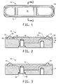
- Fig. 1 shows a plan view of the gate valve door seal assembly 10 of this invention wherein a deformable seal ring 12 is mounted in a groove near the periphery of the sealing surface of door 14 and held in place by securing means 16.
- Fig. 2 shows, in cross-section along 2-2, the door assembly.
- Seal ring 12 is reversibly mounted on the base 18 of a groove on the sealing surface of door 14.
- the groove has an outer side wall 20 and an outer lip 22 for complementarily engaging a relatively thin outer portion 30 of deformable seal ring 12.
- Securing means 16 has an outer side wall 24 and outer lip 26 for complementarily engaging a relatively thin inner portion 32 of deformable seal ring 12.
- Seal ring 12 has a relatively thick portion 34 located between thin portions 30 and 32. Thick portion 34 is generally parabolic-shaped and it is sized to extend above the lips of both door 14 and securing means 16 for sealing engagement with the surface (i.e. mating flange) surrounding the opening in the valve (not shown).
- the shape of seal ring 12 results in the requirement for only a relatively minor compressive force in order to form an effective seal under high vacuum. Much more force would be required if seal ring 12 were an O-ring.
- securing means 16 is shown as a solid disk or wedge in both Fig. 1 and Fig. 2, one skilled in the art would readily recognize that the securing means could equally be a continuous ring, a non-continuous ring, or a series of brackets. Such alternate embodiments are contemplated in this invention.
- Securing means 16 is reversibly attached to door 14 by fastening means 28.
- Fastening means 28 may include bolts (as shown in Fig. 2), screws, pins, adhesives, etc. Such alternative embodiments are included in the present invention.
- the number and location of fastening means required to adequately attach securing means 16 to door 14 depends upon the shape and size of the securing means and may be readily determined by the skilled practitioner.
- Second seal 36 is used with fastening means 28 (Fig. 3) to form an airtight seal between the fastening means and the door. This ensures that a vacuum leak does not occur due to poor mating between door 14, seal ring 12 and securing means 16.
- Second seal 36 may be a washer, O-ring, square gasket, or the like.
- Door 14 and securing means 16 can be fabricated from metals such as stainless steel, aluminum, or other non-deformable metal.
- the door and securing means may be made of the same material or of different material.
- Securing means 16 can also be made from polymers having either a modulus or a hardness much greater than that of the material used as the seal ring 12.
- Polymers, useful for preparation of the securing means include, but are not limited to nylon, polyether ether ketone (PEEK), polyether sulfone (PES), polytetrafluoroethylene (PTFE), polyimide, or an organic or inorganic composite.
- PEEK polyether ether ketone
- PES polyether sulfone
- PTFE polytetrafluoroethylene
- the door and securing means are made of steel or aluminum, most preferably a stainless steel such as 316L, or anodized aluminum.
- Seal ring 12 may be fashioned out of elastomer (preferably) or other deformable material such as a thermoplastic resin (e.g. copolymers of tetrafluoroethylene) that is thermally stable and inert to the plasma which is employed in the chip manufacturing equipment.
- a thermoplastic resin e.g. copolymers of tetrafluoroethylene
- Suitable elastomers include silicone rubber, nitrile rubber, hydrogenated nitrile rubber, EPDM, copolymers of ethylene and an alpha olefin having at least four carbon atoms, and fluoroelastomers, including perfluoroelastomers.
- a perfluoroelastomer is the preferred elastomer.
- perfluoroelastomer copolymers comprising copolymerized units of tetrafluoroethylene and copolymerized units of a perfluoro(alkyl vinyl ether) or a perfluoro(alkoxy vinyl ether). Such copolymers may also contain a minor amount (preferably less than 7 mole percent, based on the total number of moles of comonomers) of a cure site such as Br, I, CN, or H.
- Perfluoroelastomers have been extensively described in the prior art. See, for example, U.S. Patent Nos. 4,035,565; 4,281,092; 4,529,784; 4,487,903; 5,789,489; 5,936,060; 6,140,437; 6,211,319 B1 and 6,281,296 B1.
- Second seal 36 may be fashioned out of any of the materials mentioned above as suitable for seal ring 12. However, since second seal 36 is never exposed to plasmas, it need not be made from expensive perfluoroelastomer or other plasma inert material.
- Worn seal ring 12 may easily be replaced in the present invention by the steps of a) disengaging fastening means 28, b) removing securing means 16, c) replacing the worn seal ring with a new seal ring, d) repositioning securing means 16 and e) engaging fastening means 28.
- the new seal ring easily slides into the groove without twisting.
- Finite Element Analysis (FEA) studies of the slit valve door seal assembly of the present invention and of the door seal assembly of U.S. Patent No. 5,579,718 indicate that the door seal of the present invention has a higher contact pressure against the mating flange (while under the same compressive load) than does the U.S. 5,579,718 door seal assembly. This results in better vacuum sealing performance for the seal assembly of the present invention.
- FEA Finite Element Analysis
Landscapes
- Engineering & Computer Science (AREA)
- General Engineering & Computer Science (AREA)
- Mechanical Engineering (AREA)
- Gasket Seals (AREA)
- Sliding Valves (AREA)
Claims (8)
- Ensemble joint de robinet-vanne comprenant:a) une porte (14) pourvue d'une rainure pour recevoir un anneau d'étanchéité (12), ladite rainure étant formée près d'une périphérie de ladite porte, et dans lequel une première partie de ladite rainure est formée d'une base (18), d'une paroi latérale extérieure (20) et d'une lèvre extérieure (22) dans ladite porte;b) un moyen de fixation (16) pour maintenir un anneau d'étanchéité (12) à l'intérieur de ladite rainure sur ladite porte (14), ledit moyen de fixation (16) étant pourvu d'une paroi latérale extérieure (24) et d'une lèvre (26) qui forme une deuxième partie de ladite rainure;c) un moyen d'attache (28) pour attacher de manière réversible ledit moyen de fixation (16) sur ladite porte (14), ledit moyen d'attache (28) étant pourvu d'un second joint d'étanchéité (36) entre ledit moyen d'attache (28) et ladite porte (14); etd) un anneau d'étanchéité déformable (12) doté d'une forme et d'une dimension lui permettant de s'adapter de manière complémentaire à l'intérieur de ladite rainure,caractérisé par le fait que ledit anneau d'étanchéité (12) comprend une première partie mince (30) pour entrer en contact de façon complémentaire avec ladite première partie de ladite rainure et une seconde partie mince (32) pour entrer en contact de façon complémentaire avec ladite seconde partie de ladite rainure, ledit anneau d'étanchéité (12) étant pourvu d'une partie à section transversale de forme parabolique (34) située entre lesdites première (30) et seconde (32) parties minces et dimensionnée de manière à s'étendre au-delà à la fois de ladite lèvre (22) dans la porte et de ladite lèvre (26) du moyen de fixation.
- Ensemble joint de robinet-vanne selon la revendication 1, dans lequel ledit moyen de fixation (16) est sélectionné dans le groupe comprenant une clavette, un disque, un anneau continu, un anneau non-continu et des pattes.
- Ensemble joint de robinet-vanne selon la revendication 2, dans lequel ledit moyen de fixation (16) est fabriqué dans un matériau sélectionné dans le groupe comprenant l'acier inoxydable et l'aluminium.
- Ensemble joint de robinet-vanne selon la revendication 2, dans lequel ledit moyen de fixation (16) est fabriqué dans un matériau sélectionné dans le groupe comprenant le nylon, le polyétheréther-cétone, le polyéther sulfone, le polytétrafluoréthylène, un polyimide, un composé organique et un composé inorganique.
- Ensemble joint de robinet-vanne selon la revendication 1, dans lequel ledit anneau d'étanchéité (12) est fabriqué dans un matériau sélectionné dans le groupe comprenant un élastomère et une résine thermoplastique.
- Ensemble joint de robinet-vanne selon la revendication 5, dans lequel ledit anneau d'étanchéité (12) est fabriqué dans un matériau sélectionné dans le groupe comprenant un caoutchouc silicone, un caoutchouc nitrile, un caoutchouc nitrile hydrogéné, le EPDM, des copolymères d'éthylène et une alpha-oléfine possédant au moins quatre atomes de carbone, des fluoroélastomères et des perfluoroélastomères.
- Ensemble joint de robinet-vanne selon la revendication 6, dans lequel ledit anneau d'étanchéité (12) est fabriqué dans un perfluoroélastomère.
- Ensemble joint de robinet-vanne selon la revendication 1, dans lequel ledit moyen d'attache (28) est sélectionné dans le groupe comprenant des boulons et des vis.
Applications Claiming Priority (5)
| Application Number | Priority Date | Filing Date | Title |
|---|---|---|---|
| US35340002P | 2002-01-31 | 2002-01-31 | |
| US34683303A | 2003-01-17 | 2003-01-17 | |
| US346833 | 2003-01-17 | ||
| PCT/US2003/002533 WO2003064900A1 (fr) | 2002-01-31 | 2003-01-29 | Ensemble joint de robinet-vanne |
| US353400P | 2010-06-10 |
Publications (2)
| Publication Number | Publication Date |
|---|---|
| EP1470351A1 EP1470351A1 (fr) | 2004-10-27 |
| EP1470351B1 true EP1470351B1 (fr) | 2007-02-28 |
Family
ID=27668977
Family Applications (1)
| Application Number | Title | Priority Date | Filing Date |
|---|---|---|---|
| EP03705948A Expired - Lifetime EP1470351B1 (fr) | 2002-01-31 | 2003-01-29 | Ensemble joint de robinet-vanne |
Country Status (7)
| Country | Link |
|---|---|
| US (2) | US6932354B2 (fr) |
| EP (1) | EP1470351B1 (fr) |
| JP (1) | JP4149931B2 (fr) |
| KR (1) | KR100909332B1 (fr) |
| DE (1) | DE60312127T2 (fr) |
| TW (1) | TWI275724B (fr) |
| WO (1) | WO2003064900A1 (fr) |
Families Citing this family (32)
| Publication number | Priority date | Publication date | Assignee | Title |
|---|---|---|---|---|
| US7040060B2 (en) * | 2003-01-23 | 2006-05-09 | Saratoga Spa & Bath, Inc. | Mounting elements, mounting arrangements, and methods for mounting liners to structures in pools and spas |
| JP4430884B2 (ja) * | 2003-04-14 | 2010-03-10 | 日本バルカー工業株式会社 | 蟻溝用シール材 |
| JP2005050728A (ja) * | 2003-07-30 | 2005-02-24 | Nichias Corp | 燃料電池のセパレータ用ゴムガスケット |
| CN100378377C (zh) * | 2004-02-27 | 2008-04-02 | 丰田自动车株式会社 | 密封件 |
| US8648977B2 (en) * | 2004-06-02 | 2014-02-11 | Applied Materials, Inc. | Methods and apparatus for providing a floating seal having an isolated sealing surface for chamber doors |
| KR100716041B1 (ko) * | 2004-06-02 | 2007-05-09 | 어플라이드 머티어리얼스, 인코포레이티드 | 챔버를 밀봉하기 위한 방법 및 장치 |
| US7282097B2 (en) * | 2004-06-14 | 2007-10-16 | Applied Materials, Inc. | Slit valve door seal |
| KR101137725B1 (ko) * | 2004-10-26 | 2012-04-24 | 주성엔지니어링(주) | 반도체 제조 장치용 슬롯 밸브 |
| US7070187B2 (en) * | 2004-11-09 | 2006-07-04 | Federal-Mogul World Wide, Inc | Gasket assembly |
| US20070092385A1 (en) * | 2005-10-20 | 2007-04-26 | Petrie Pe Greg A | Pump and valve actuator system and method |
| US8074967B2 (en) * | 2006-06-29 | 2011-12-13 | Nippon Valqua Industries, Ltd. | Gate valve for vacuum and seal member used therefor |
| WO2008046048A2 (fr) * | 2006-10-12 | 2008-04-17 | Parker-Hannifin Corporation | Ensemble de trappe de soupape à fente |
| EP1953802A3 (fr) * | 2007-02-01 | 2012-05-23 | Parker-Hannifin Corporation | Chambre de procédés pour semiconducteur |
| KR100892781B1 (ko) * | 2007-02-12 | 2009-04-15 | 주식회사 휴먼메디텍 | 진공챔버용 도어 |
| US20080265523A1 (en) * | 2007-04-30 | 2008-10-30 | Freudenberg-Nok General Partnership | Asymmetric Gasket |
| US20080315141A1 (en) * | 2007-06-25 | 2008-12-25 | Greene, Tweed Of Delaware, Inc. | Slit Valve Door |
| WO2009055507A1 (fr) * | 2007-10-26 | 2009-04-30 | Applied Materials, Inc. | Procedes et appareil de fermeture hermetique d'un obturateur de clapet à fente |
| US20090184279A1 (en) * | 2008-01-23 | 2009-07-23 | Buckhorn Rubber Products, Inc. | Wedge and covered insert assembly |
| JP5355578B2 (ja) * | 2008-09-18 | 2013-11-27 | 日本バルカー工業株式会社 | シールプレートおよびシールプレートに用いられるシール部材ならびにこれらの製造方法 |
| US20110031702A1 (en) * | 2009-08-07 | 2011-02-10 | Wilson D Bruce | Polyimide resin gaskets for diss outlet valves |
| US9010718B2 (en) * | 2009-08-10 | 2015-04-21 | Dean Foote | Seal assembly for a pressure plate in a blowout preventer |
| US8225767B2 (en) * | 2010-03-15 | 2012-07-24 | Tinney Joseph F | Positive displacement rotary system |
| US8623145B2 (en) * | 2010-03-25 | 2014-01-07 | Parker-Hannifin Corporation | Substrate processing apparatus with composite seal |
| ITMI20120694A1 (it) * | 2012-04-26 | 2013-10-27 | Mib Italiana Spa | Valvola di controllo a petali con guarnizione di tenuta per unita' di collegamento separabili per tubi flessibili. |
| US20130319557A1 (en) * | 2012-06-05 | 2013-12-05 | Hunting Energy Services, Inc. | Metal Reinforced Seal Plate for Pilot Actuated Spool Valve |
| KR101493909B1 (ko) * | 2014-06-10 | 2015-02-17 | 김형규 | 개폐 밸브 |
| JP6908603B2 (ja) | 2015-11-11 | 2021-07-28 | グリーン, ツイード テクノロジーズ, インコーポレイテッド | 高温最終用途のためのシールリングおよびシールリングアセンブリ |
| JP7633204B2 (ja) * | 2022-03-31 | 2025-02-19 | 東京エレクトロン株式会社 | ゲートバルブ装置及び半導体製造装置 |
| US12535149B2 (en) * | 2022-06-30 | 2026-01-27 | Srt Co., Ltd | Sealing blade for a slit valve |
| US11867307B1 (en) * | 2022-07-28 | 2024-01-09 | Applied Materials, Inc. | Multi-piece slit valve gate |
| KR102802067B1 (ko) * | 2023-02-14 | 2025-05-02 | (주)다산이엔지 | 진공 게이트 밸브 |
| US20250060041A1 (en) * | 2023-08-17 | 2025-02-20 | Applied Materials, Inc. | Multi-piece slit valve gate |
Family Cites Families (17)
| Publication number | Priority date | Publication date | Assignee | Title |
|---|---|---|---|---|
| US2665461A (en) * | 1949-07-30 | 1954-01-12 | Willys Motors Inc | Blow plate seal for core blowing machines |
| US2870987A (en) * | 1955-07-08 | 1959-01-27 | Dolphice H Greenwood | Gate valve and sealing means therefor |
| GB1280712A (en) | 1969-10-25 | 1972-07-05 | Glenfield & Kennedy Ltd | Improvements in or relating to sealing devices |
| US4035565A (en) | 1975-03-27 | 1977-07-12 | E. I. Du Pont De Nemours And Company | Fluoropolymer containing a small amount of bromine-containing olefin units |
| US4281092A (en) | 1978-11-30 | 1981-07-28 | E. I. Du Pont De Nemours And Company | Vulcanizable fluorinated copolymers |
| JPS5871906A (ja) | 1981-10-22 | 1983-04-28 | Daikin Ind Ltd | 含フツ素弾性状共重合体の製法 |
| AU555553B2 (en) * | 1981-10-27 | 1986-10-02 | Arthur Malcolm Bennett | Valve member |
| US4529784A (en) | 1983-07-11 | 1985-07-16 | E. I. Du Pont De Nemours And Company | Fluorinated copolymers with improved cure site |
| US5013009A (en) * | 1989-08-04 | 1991-05-07 | Goddard Valve Corporation | Top entry valve |
| US5482297A (en) | 1995-01-09 | 1996-01-09 | Greene, Tweed Of Delaware, Inc. | Seal element for installation in an annular dove-tail groove |
| US5579718A (en) | 1995-03-31 | 1996-12-03 | Applied Materials, Inc. | Slit valve door |
| US6140437A (en) | 1995-12-28 | 2000-10-31 | Daikin Industries Ltd. | Fluorine-containing elastic copolymers, curable composition containing the same and sealant made therefrom |
| US5877264A (en) | 1996-11-25 | 1999-03-02 | E. I. Du Pont De Nemours And Company | Fast-curing perfluoroelastomer composition |
| US5936060A (en) | 1996-11-25 | 1999-08-10 | E. I. Du Pont De Nemours And Company | Perfluoroelastomer composition having improved processability |
| US6089543A (en) | 1997-07-11 | 2000-07-18 | Applied Materials, Inc. | Two-piece slit valve door with molded-in-place seal for a vacuum processing system |
| US6089537A (en) * | 1999-06-23 | 2000-07-18 | Mks Instruments, Inc. | Pendulum valve assembly |
| US6409149B1 (en) * | 2000-06-28 | 2002-06-25 | Mks Instruments, Inc. | Dual pendulum valve assembly with valve seat cover |
-
2003
- 2003-01-29 JP JP2003564465A patent/JP4149931B2/ja not_active Expired - Fee Related
- 2003-01-29 EP EP03705948A patent/EP1470351B1/fr not_active Expired - Lifetime
- 2003-01-29 WO PCT/US2003/002533 patent/WO2003064900A1/fr not_active Ceased
- 2003-01-29 DE DE60312127T patent/DE60312127T2/de not_active Expired - Lifetime
- 2003-01-29 KR KR1020047011683A patent/KR100909332B1/ko not_active Expired - Fee Related
- 2003-01-30 TW TW092102193A patent/TWI275724B/zh active
- 2003-02-06 US US10/359,374 patent/US6932354B2/en not_active Expired - Fee Related
-
2004
- 2004-10-07 US US10/960,799 patent/US20050046123A1/en not_active Abandoned
Also Published As
| Publication number | Publication date |
|---|---|
| WO2003064900A1 (fr) | 2003-08-07 |
| US6932354B2 (en) | 2005-08-23 |
| TWI275724B (en) | 2007-03-11 |
| DE60312127D1 (de) | 2007-04-12 |
| US20050046123A1 (en) | 2005-03-03 |
| TW200302907A (en) | 2003-08-16 |
| EP1470351A1 (fr) | 2004-10-27 |
| DE60312127T2 (de) | 2007-11-15 |
| KR100909332B1 (ko) | 2009-07-24 |
| KR20040079959A (ko) | 2004-09-16 |
| JP4149931B2 (ja) | 2008-09-17 |
| US20030164596A1 (en) | 2003-09-04 |
| JP2005516169A (ja) | 2005-06-02 |
Similar Documents
| Publication | Publication Date | Title |
|---|---|---|
| US6932354B2 (en) | Valve seal assembly | |
| US6213476B1 (en) | Bi-modulus composite seal and its method of manufacture | |
| US20060273277A1 (en) | Plasma resistant seal assembly with replaceable barrier shield | |
| US20110018211A1 (en) | Seal Material | |
| US20080315141A1 (en) | Slit Valve Door | |
| US9580956B2 (en) | Methods and apparatus for providing a floating seal for chamber doors | |
| KR20090017453A (ko) | 슬릿 밸브 도어 또는 슬릿 밸브, 및 슬릿 밸브 조립체 | |
| US6620361B1 (en) | Method of manufacturing a composite seal | |
| US20060066061A1 (en) | Seal | |
| US20050285354A1 (en) | Sealing construction | |
| US8496252B2 (en) | Seal | |
| JP4486385B2 (ja) | 弁装置用のシールプレート | |
| JPH09177976A (ja) | 金属中空oリング | |
| JP5592727B2 (ja) | シールプレートおよびこれに用いられるシール材 | |
| US20240247726A1 (en) | A cock for a valve and a valve comprising such cock | |
| JP5126462B2 (ja) | 燃料電池用シール構造 | |
| JP4625746B2 (ja) | シール材 | |
| US20240402128A1 (en) | Qcm sensor | |
| US20240218930A1 (en) | Self energized seal and methods of making and using the same | |
| WO2008046048A2 (fr) | Ensemble de trappe de soupape à fente | |
| KR102828307B1 (ko) | 진공 펌프를 위한 시일 | |
| KR20090049230A (ko) | 탄성 금속링 패킹이 설치된 볼 밸브 | |
| WO2007149530A2 (fr) | Trappe de soupape à fente | |
| KR101041148B1 (ko) | 반도체 제조장치의 공정챔버 클로징 조립체의 슬릿밸브 | |
| JP2004044621A (ja) | 金属シール |
Legal Events
| Date | Code | Title | Description |
|---|---|---|---|
| PUAI | Public reference made under article 153(3) epc to a published international application that has entered the european phase |
Free format text: ORIGINAL CODE: 0009012 |
|
| 17P | Request for examination filed |
Effective date: 20040730 |
|
| AK | Designated contracting states |
Kind code of ref document: A1 Designated state(s): AT BE BG CH CY CZ DE DK EE ES FI FR GB GR IE IT LI LU MC NL PT SE SI SK TR |
|
| RIN1 | Information on inventor provided before grant (corrected) |
Inventor name: TAKAHASHI, KOHTARO Inventor name: MINOWA, NORIHISA |
|
| RIN1 | Information on inventor provided before grant (corrected) |
Inventor name: MINOWA, NORIHISA Inventor name: TAKAHASHI, KOHTARO |
|
| GRAP | Despatch of communication of intention to grant a patent |
Free format text: ORIGINAL CODE: EPIDOSNIGR1 |
|
| GRAS | Grant fee paid |
Free format text: ORIGINAL CODE: EPIDOSNIGR3 |
|
| GRAA | (expected) grant |
Free format text: ORIGINAL CODE: 0009210 |
|
| AK | Designated contracting states |
Kind code of ref document: B1 Designated state(s): CH DE GB LI |
|
| REG | Reference to a national code |
Ref country code: GB Ref legal event code: FG4D |
|
| REG | Reference to a national code |
Ref country code: CH Ref legal event code: EP |
|
| REF | Corresponds to: |
Ref document number: 60312127 Country of ref document: DE Date of ref document: 20070412 Kind code of ref document: P |
|
| REG | Reference to a national code |
Ref country code: CH Ref legal event code: NV Representative=s name: RITSCHER & PARTNER AG |
|
| PLBE | No opposition filed within time limit |
Free format text: ORIGINAL CODE: 0009261 |
|
| STAA | Information on the status of an ep patent application or granted ep patent |
Free format text: STATUS: NO OPPOSITION FILED WITHIN TIME LIMIT |
|
| 26N | No opposition filed |
Effective date: 20071129 |
|
| REG | Reference to a national code |
Ref country code: CH Ref legal event code: PCAR Free format text: RITSCHER & PARTNER AG;RESIRAIN 1;8125 ZOLLIKERBERG (CH) |
|
| PGFP | Annual fee paid to national office [announced via postgrant information from national office to epo] |
Ref country code: CH Payment date: 20110112 Year of fee payment: 9 Ref country code: DE Payment date: 20110126 Year of fee payment: 9 |
|
| PGFP | Annual fee paid to national office [announced via postgrant information from national office to epo] |
Ref country code: GB Payment date: 20110126 Year of fee payment: 9 |
|
| REG | Reference to a national code |
Ref country code: CH Ref legal event code: PL |
|
| GBPC | Gb: european patent ceased through non-payment of renewal fee |
Effective date: 20120129 |
|
| PG25 | Lapsed in a contracting state [announced via postgrant information from national office to epo] |
Ref country code: LI Free format text: LAPSE BECAUSE OF NON-PAYMENT OF DUE FEES Effective date: 20120131 Ref country code: GB Free format text: LAPSE BECAUSE OF NON-PAYMENT OF DUE FEES Effective date: 20120129 Ref country code: DE Free format text: LAPSE BECAUSE OF NON-PAYMENT OF DUE FEES Effective date: 20120801 Ref country code: CH Free format text: LAPSE BECAUSE OF NON-PAYMENT OF DUE FEES Effective date: 20120131 |
|
| REG | Reference to a national code |
Ref country code: DE Ref legal event code: R119 Ref document number: 60312127 Country of ref document: DE Effective date: 20120801 |