EP1470865A2 - Buse et appareil de nettoyage - Google Patents
Buse et appareil de nettoyage Download PDFInfo
- Publication number
- EP1470865A2 EP1470865A2 EP20040017546 EP04017546A EP1470865A2 EP 1470865 A2 EP1470865 A2 EP 1470865A2 EP 20040017546 EP20040017546 EP 20040017546 EP 04017546 A EP04017546 A EP 04017546A EP 1470865 A2 EP1470865 A2 EP 1470865A2
- Authority
- EP
- European Patent Office
- Prior art keywords
- gas
- nozzle
- liquid
- cleaning
- ejection port
- Prior art date
- Legal status (The legal status is an assumption and is not a legal conclusion. Google has not performed a legal analysis and makes no representation as to the accuracy of the status listed.)
- Withdrawn
Links
- 238000004140 cleaning Methods 0.000 title claims abstract description 167
- 239000007788 liquid Substances 0.000 claims abstract description 198
- 239000000843 powder Substances 0.000 claims abstract description 54
- 238000002347 injection Methods 0.000 claims abstract description 9
- 239000007924 injection Substances 0.000 claims abstract description 9
- 239000000203 mixture Substances 0.000 claims description 31
- 230000002265 prevention Effects 0.000 claims description 20
- 238000011144 upstream manufacturing Methods 0.000 abstract description 53
- 230000001965 increasing effect Effects 0.000 description 19
- 239000000463 material Substances 0.000 description 14
- UIIMBOGNXHQVGW-UHFFFAOYSA-M Sodium bicarbonate Chemical compound [Na+].OC([O-])=O UIIMBOGNXHQVGW-UHFFFAOYSA-M 0.000 description 10
- 238000010276 construction Methods 0.000 description 9
- 230000002349 favourable effect Effects 0.000 description 9
- 230000001133 acceleration Effects 0.000 description 6
- 230000007423 decrease Effects 0.000 description 6
- XLYOFNOQVPJJNP-UHFFFAOYSA-N water Substances O XLYOFNOQVPJJNP-UHFFFAOYSA-N 0.000 description 6
- 229910000030 sodium bicarbonate Inorganic materials 0.000 description 5
- 235000017557 sodium bicarbonate Nutrition 0.000 description 5
- 238000000034 method Methods 0.000 description 4
- 238000007796 conventional method Methods 0.000 description 3
- 230000032798 delamination Effects 0.000 description 3
- 238000010586 diagram Methods 0.000 description 3
- 238000002474 experimental method Methods 0.000 description 3
- 239000002245 particle Substances 0.000 description 3
- 238000005406 washing Methods 0.000 description 3
- 239000000654 additive Substances 0.000 description 2
- 230000003247 decreasing effect Effects 0.000 description 2
- 150000002500 ions Chemical class 0.000 description 2
- 230000002195 synergetic effect Effects 0.000 description 2
- 239000008399 tap water Substances 0.000 description 2
- 235000020679 tap water Nutrition 0.000 description 2
- PNEYBMLMFCGWSK-UHFFFAOYSA-N aluminium oxide Inorganic materials [O-2].[O-2].[O-2].[Al+3].[Al+3] PNEYBMLMFCGWSK-UHFFFAOYSA-N 0.000 description 1
- 230000000593 degrading effect Effects 0.000 description 1
- 230000000694 effects Effects 0.000 description 1
- 238000005516 engineering process Methods 0.000 description 1
- 238000011089 mechanical engineering Methods 0.000 description 1
- 230000000704 physical effect Effects 0.000 description 1
- 230000010349 pulsation Effects 0.000 description 1
- 238000009751 slip forming Methods 0.000 description 1
- 239000007787 solid Substances 0.000 description 1
- 230000001954 sterilising effect Effects 0.000 description 1
- 239000004094 surface-active agent Substances 0.000 description 1
- 239000004552 water soluble powder Substances 0.000 description 1
- NWONKYPBYAMBJT-UHFFFAOYSA-L zinc sulfate Chemical compound [Zn+2].[O-]S([O-])(=O)=O NWONKYPBYAMBJT-UHFFFAOYSA-L 0.000 description 1
Images






Classifications
-
- B—PERFORMING OPERATIONS; TRANSPORTING
- B08—CLEANING
- B08B—CLEANING IN GENERAL; PREVENTION OF FOULING IN GENERAL
- B08B3/00—Cleaning by methods involving the use or presence of liquid or steam
- B08B3/02—Cleaning by the force of jets or sprays
-
- B—PERFORMING OPERATIONS; TRANSPORTING
- B05—SPRAYING OR ATOMISING IN GENERAL; APPLYING FLUENT MATERIALS TO SURFACES, IN GENERAL
- B05B—SPRAYING APPARATUS; ATOMISING APPARATUS; NOZZLES
- B05B7/00—Spraying apparatus for discharge of liquids or other fluent materials from two or more sources, e.g. of liquid and air, of powder and gas
- B05B7/14—Spraying apparatus for discharge of liquids or other fluent materials from two or more sources, e.g. of liquid and air, of powder and gas designed for spraying particulate materials
- B05B7/1404—Arrangements for supplying particulate material
- B05B7/1431—Arrangements for supplying particulate material comprising means for supplying an additional liquid
-
- B—PERFORMING OPERATIONS; TRANSPORTING
- B05—SPRAYING OR ATOMISING IN GENERAL; APPLYING FLUENT MATERIALS TO SURFACES, IN GENERAL
- B05B—SPRAYING APPARATUS; ATOMISING APPARATUS; NOZZLES
- B05B15/00—Details of spraying plant or spraying apparatus not otherwise provided for; Accessories
- B05B15/50—Arrangements for cleaning; Arrangements for preventing deposits, drying-out or blockage; Arrangements for detecting improper discharge caused by the presence of foreign matter
- B05B15/55—Arrangements for cleaning; Arrangements for preventing deposits, drying-out or blockage; Arrangements for detecting improper discharge caused by the presence of foreign matter using cleaning fluids
-
- B—PERFORMING OPERATIONS; TRANSPORTING
- B05—SPRAYING OR ATOMISING IN GENERAL; APPLYING FLUENT MATERIALS TO SURFACES, IN GENERAL
- B05B—SPRAYING APPARATUS; ATOMISING APPARATUS; NOZZLES
- B05B7/00—Spraying apparatus for discharge of liquids or other fluent materials from two or more sources, e.g. of liquid and air, of powder and gas
- B05B7/02—Spray pistols; Apparatus for discharge
- B05B7/04—Spray pistols; Apparatus for discharge with arrangements for mixing liquids or other fluent materials before discharge
- B05B7/0416—Spray pistols; Apparatus for discharge with arrangements for mixing liquids or other fluent materials before discharge with arrangements for mixing one gas and one liquid
- B05B7/0441—Spray pistols; Apparatus for discharge with arrangements for mixing liquids or other fluent materials before discharge with arrangements for mixing one gas and one liquid with one inner conduit of liquid surrounded by an external conduit of gas upstream the mixing chamber
- B05B7/0475—Spray pistols; Apparatus for discharge with arrangements for mixing liquids or other fluent materials before discharge with arrangements for mixing one gas and one liquid with one inner conduit of liquid surrounded by an external conduit of gas upstream the mixing chamber with means for deflecting the peripheral gas flow towards the central liquid flow
-
- B—PERFORMING OPERATIONS; TRANSPORTING
- B24—GRINDING; POLISHING
- B24C—ABRASIVE OR RELATED BLASTING WITH PARTICULATE MATERIAL
- B24C11/00—Selection of abrasive materials or additives for abrasive blasts
- B24C11/005—Selection of abrasive materials or additives for abrasive blasts of additives, e.g. anti-corrosive or disinfecting agents in solid, liquid or gaseous form
-
- B—PERFORMING OPERATIONS; TRANSPORTING
- B24—GRINDING; POLISHING
- B24C—ABRASIVE OR RELATED BLASTING WITH PARTICULATE MATERIAL
- B24C5/00—Devices or accessories for generating abrasive blasts
- B24C5/02—Blast guns, e.g. for generating high velocity abrasive fluid jets for cutting materials
-
- B—PERFORMING OPERATIONS; TRANSPORTING
- B24—GRINDING; POLISHING
- B24C—ABRASIVE OR RELATED BLASTING WITH PARTICULATE MATERIAL
- B24C5/00—Devices or accessories for generating abrasive blasts
- B24C5/02—Blast guns, e.g. for generating high velocity abrasive fluid jets for cutting materials
- B24C5/04—Nozzles therefor
-
- B—PERFORMING OPERATIONS; TRANSPORTING
- B24—GRINDING; POLISHING
- B24C—ABRASIVE OR RELATED BLASTING WITH PARTICULATE MATERIAL
- B24C7/00—Equipment for feeding abrasive material; Controlling the flowability, constitution, or other physical characteristics of abrasive blasts
- B24C7/0046—Equipment for feeding abrasive material; Controlling the flowability, constitution, or other physical characteristics of abrasive blasts the abrasive material being fed in a gaseous carrier
- B24C7/0076—Equipment for feeding abrasive material; Controlling the flowability, constitution, or other physical characteristics of abrasive blasts the abrasive material being fed in a gaseous carrier the blasting medium being a liquid stream
Definitions
- the present invention relates to a cleaning nozzle applicable to a wide range of cleaning operations on automobiles, buildings' wall surfaces, bottles and dishes, and more specifically to an improved cleaning nozzle that has an improved performance of mixing and accelerating a gas and a cleaning liquid to enhance a uniformity of the gas-liquid mixture flow containing droplets of the cleaning liquid and to eject the liquid droplets at high speed.
- This invention also relates to an improved technique to prevent a passage clogging due to a powder material which can occur when the powder material is used to take advantage of its delaminating action in further improving the performance of removing sticky dirt.
- the cleaning nozzle of this kind for ejecting a gas-liquid mixture flow is known to be available in two types: one in which a gas ejection port is provided on the outside, enclosing a liquid ejection port, and one in which a liquid ejection port is provided on the outside, enclosing a gas ejection port.
- the present invention relates to an improvement in the former type in which the gas ejection port is provided on the outside.
- the state and ejection speed of the gas-liquid mixture flow ejected from the cleaning nozzle are important.
- a gas ejection portion in the nozzle is formed as a converging-diverging tube, which is once narrowed and progressively expands toward the downstream end thereafter, in order to accelerate the gas to a sonic or supersonic speed before mixing it with a liquid.
- This conventional technology has the following drawbacks. Because a ring-shaped ejection port, which is installed in the narrow gas ejection portion in the nozzle, must have a narrow converging-diverging shape in a longitudinal cross section, not only does the structure of the gas ejection portion become complex and difficult to machine but also the nozzle cannot always eject a high-speed gas-liquid mixture flow.
- a Laval nozzle or converging-diverging nozzle which has a trumpet-shaped portion in front of a minimum diameter portion and a diverging tapered portion after the minimum diameter portion
- the flow speed at the rear tapered portion increases to a sonic speed or even supersonic speed -- a speed increasing phenomenon widely known in the fluidics (see "Mechanical Engineering Handbook” published by Japan Mechanical Engineers Association (Nihon Kikai Gakkai) (April 15, 1987), A5 - page 58).
- the powder used is water-soluble powder, such as sodium hydrogencarbonate
- the powder easily absorbs humidity and turns into a solid lump that adheres to the wall surface of the passage. Further, the powder easily adheres to and cloggs on protrusions and stepped portions in a passage of the cleaning nozzle.
- the passage may be damaged.
- the present invention has been accomplished under these technical situations. It is an object of the present invention to provide a cleaning nozzle which efficiently transfers the energy of the pressurized gas flow to liquid droplets to accelerate the mixing of gas and cleaning liquid in the trumpet-shaped portion and thereby improve the uniformity of the liquid droplets making up the gas-liquid mixture flow produced in the trumpet-shaped portion; and which further mixes and accelerates the liquid droplets in a passage downstream of the trumpet-shaped portion to produce a powerful, uniformly mixed high-speed droplet jet flow with an improved cleaning capability.
- the present invention from the first aspect adopts a technical concept which comprises: a trumpet-shaped portion formed by multiple inclined portions at a location upstream of a minimum diameter portion of an ejection nozzle portion; a gas ejection port formed along the inclined portions and opened to an intermediate part of the trumpet-shaped portion; an inclined portion having its inclination angle with respect to an axis of the ejection nozzle portion set smaller than an ejection angle of the gas ejection port and interposed between the gas eject ion port and the minimum diameter portion; and a cleaning liquid ejection port formed inside the gas ejection port; wherein a gas is ejected from its associated ejection port at a speed higher than that of a cleaning liquid to transform the cleaning liquid into droplets and at the same time accelerate them.
- Fig. 1 is an essential-part construction diagram showing the feature of the invention from the aforementioned first aspect.
- a trumpet-shaped portion formed upstream of a minimum diameter portion 2 of an ejection nozzle portion 1 is constructed of multiple inclined portions 3, 4.
- a gas ejection port 5 is formed along the inclined portion 3, and an inclined portion 4 with a small inclination angle is interposed between the gas ejection port 5 and the minimum diameter portion 2 to expand a gas-liquid mixing space immediately upstream of the minimum diameter portion 2.
- the cleaning liquid ejected in a liquid flow state is transformed into droplets which are thenacceleratedbythegasjetacceleratedbythetrumpet-shaped portion.
- the gas ejection port is formed along the trumpet-shaped portion, which is located upstream of the minimum diameter portion of the converging-diverging nozzle portion, the gas jet flow converges into the central portion as it effectively mixes with the cleaning liquid jet flow and the droplets formed as a result of the mixing of gas and liquid are accelerated. Then, the cleaning liquid droplets formed and accelerated by the trumpet-shaped portion are further accelerated effectively at a location downstream of the minimum diameter portion by the speed increasing phenomenon of the converging-diverging nozzle.
- the gas jet flow passing through the central part of the gas ejection port is made to converge at a point upstream of the minimum diameter portion so that the gas-liquid mixture flow converges immediately before the minimum diameter portion, the gas-liquid mixing action can further be improved. If the cross-sectional area of the gas ejection port perpendicular to the axis direction is reduced progressively toward its downstream open end, the gas ejection speed can further be accelerated. Further, if the cross-sectional area of the gas ejection port at its downstream open end is set almost equal to or slightly smaller than that of the minimum diameter portion, a reduction in the flow speed can be minimized throughout the entire passage and a stable, high-speed gas-liquidmixture flow can be produced.
- the ratio between the cross-sectional area of the gas ejection port at its downstream open end and the cross-sectional area of the minimum diameter portion may be set to 1:1 to 1:1.3. Further, if the distance from the cleaning liquid ejection port to the downstream end of the ej ection nozzle portion is set to 10-50 times the diameter of the minimum diameter portion, sufficient mixing and acceleration actions in the ejection nozzle portion can be obtained, producing a uniformly mixed, high-speed droplet jet flow. Further, it is possible to supply a powder material into a passage upstream of the gas ejection port.
- a small amount of clogging prevention liquid may be injected into an intermediate section of the pressurized gas passage between the powder injection portion and the cleaning nozzle.
- the amount of clogging prevention liquid to be injecced needs only to be large enough to prevent the powder from accumulating in the passage. Too large an amount of the clogging prevention liquid injected may cause pulsations in the pressurized gas flow or reduce the speed of the pressurized gas flow. Therefore, it is desirable to set the amount of the clogging prevention liquid smaller than that of the liquid supplied to the cleaning nozzle, or smaller by weight than that of the powder injected, or smaller by volume than 1/1000 that of the pressurized gas flow. It is also effective to continue supplying the clogging prevention liquid for a predetermined duration after the injection of powder into the pressurized gas flow has been stopped.
- the cleaning nozzle of the present invention can be used widely in a variety of washing applications, such as automobiles, buildings' wall surfaces, bottles and dishes.
- the gas may include a pressurized air, a heated high-temperature gas and a high-temperature high-pressure gas such as steam.
- the cleaning liquid may use water such as tap water and an appropriate liquid mixed, as required, with additives such as surfactant to improve a cleaning performance and a sterilizing power.
- the cleaning liquid may have a pressure similar to that of the tap water but pressurizing it further to an appropriate level can produce a stronger cleaning action. Further, it is possible to mix appropriate powder of abrasive cleansing material such as sodium hydrogencarbonate and alumina into the flow upstream of the gas ejection port.
- the gas ejection port it may be constructed in the form of a plurality of hole portions arranged in a ring, as well as in the form of a ring-shaped gap as described in the following embodiment.
- the cleaning liquid ejection port too, it may be constructed in the form of a single hole portion as described in the following embodiment and in the form of a plurality of hole portions.
- the droplets may be ejected at speeds below the sonic speed.
- the shape of the trumpet-like portion it is possible to adopt a trumpet-shaped portion def ined by two or more inclined portions if the trumpet-shaped portion can be formed along some of multiple inclined portions and the gas ejection port can be opened into an intermediate part of the trumpet-shaped portion and if it is possible to interpose between the gas ejection port and the minimum diameter portion an inclined portion whose inclination angle with respect to the axis of the ejection nozzle portion is smaller than the ejection angle of the gas ejection port. It is also possible to form the trumpet-shaped portion by a curved surface.
- the shape of the gas-liquid mixture flow passage downstream of the minimum diameter portion of the ejection nozzle portion it may be formed of a straight tube with a constant diameter or a tapered tube with its inner diameter progressively increasing or decreasing downstream.
- a converging-diverging nozzle with its inner diameter on the downstream side progressively expanding toward the downstream end is employed, the so-called speed increasing effect of a tapered portion of the Laval nozzle can be taken advantage of to increase the ejection speed of the gas-liquid mixture flow from the ejection nozzle portion to a sonic or supersonic speed.
- Apractical size for the diameter of the minimum diameter portion of the converging-diverging nozzle portion as the ejection nozzle portion is about 6-16 mm.
- An appropriate length from the liquid ejection port to the front end or downstream end of the ejection nozzle portion is about 10-50 times the diameter of the minimum diameter portion.
- the inclination of the tapered portion formed downstream of the minimum diameter portion the inclination of only 1-2 degrees is enough for producing a satisfactory high-speed jet flow. Setting the inclination equal to or smaller than about 8 degrees can avoid a delamination of a boundary layer, the phenomenon that can easily occur in the gas-liquid mixture flow.
- the cross section of a passage in the trumpet-shaped portion and the ejection nozzle portion is not limited to the circular one but it may be formed flat or elliptical.
- the inner surface of the trumpet-shaped portion that constitutes the gas ejection port and the outer surface of the cleaning liquid ejection portion may be formed of a plurality of stepped inclined surfaces or of a curved surface.
- a passage for the gas-liquid mixture flow downstream of the minimum diameter portion may be formed by combining a tapered portion and a straight tube portion.
- FIG. 2 is a circuit diagram schematically showing an example application of this invention.
- reference number 10 represents a cleaning nozzle, which has a passage 11 for pressurized gas formed inside thereof.
- the passage 11 is connected at its inlet portion with a pressurized gas supply means consisting of a ) compressor 12.
- a cleaning liquid supply portion 13 around which is formed a gas flowing gap.
- An inlet portion of the cleaning liquid supply portion 13 is connected to a cleaning liquid tank 14 and a pump 15.
- the compressor 12 is connected on the downstream side with a powder supply means comprising a powder tank 16 and a feeding device 17 such as screw conveyor.
- the compressor 12 is also connected through a valve 20 with a clogging prevention water tank 18 for washing away powder adhering to the passage and with a pump 19.
- a check valve may be installed between the pump 19 and the valve 20 to prevent a backflow to the pump.
- Fig. 3 is a longitudinal cross section of the cleaning nozzle 10 according to an embodiment of this invention.
- Fig. 4 is an enlargedviewofthenozzle.
- the cleaning nozzle 10 of this embodiment comprises a cylindrical body portion 21, the cleaning liquid supply portion 13 installed inside the cylindricalbodyportion21, a gas introducingportion 22 screwed into an upstream part of the cylindrical body portion 21, and an ej ection nozzle portion 23 as a converging-diverging nozzle portion screwed into a downstream part of the cylindrical body portion 21.
- the cleaning liquid supply portion 13 comprises an accumulating portion 100 and an ejection portion 29 screwed over a downstream part of the accumulating portion 100.
- the ejection nozzle portion 23 in this embodiment comprises a first nozzle member 24 formed integral with a trumpet-shaped portion and a second nozzle member 25 tapered so that its passage progressively expands toward the downstream end. These first and second nozzle members are joined together to shape the ejection nozzle portion 23 into a long converging-diverging nozzle portion.
- the first nozzle member 24 has its inclined portion formed by three tapered portions 26-28 whose diameter progressively decreases downstream.
- a gas ejection port 31 is formed between the most upstream tapered portion 26 and a tapered portion 30 formed on the outer surface of the ejection portion 29 of the cleaning liquid supply portion 13 so that the gas jet flow converges at a point upstream of a minimum diameter portion 33 of a passage 32.
- the gap between the tapered portions 26 and 30 is progressively narrowed toward its downstream open end by differentiating the inclination angles of these tapered portions so that the cross-sectional area of the gas ejection port 31 perpendicular to the axis is reduced progressively to further accelerate the pressurized gas as it passes through the gas ejection port 31.
- the powder is accelerated along with the gas in the gas ejection port 31 and, after being ejected from the open end, is further accelerated like the liquid droplets.
- an accumulating space 34 for the cleaning liquid Inside the accumulating portion 100 of the cleaning liquid supply portion 13 is formed an accumulating space 34 for the cleaning liquid.
- An outer wall surface of an upstream part of the accumulating portion 100 forms a tapered guide surface 38.
- a passage 35 Formed inside the ejection portion 29 is a passage 35 which communicates with the accumulating space 34 and is formed at its front end portion with a cleaning liquid ejection port 36, as shown in Fig. 4.
- the cleaning liquid pressurized by the pump 15 is ejected from the cleaning liquid ejection portion 29 at high speed.
- reference number 39 denotes a cleaning liquid introducing portion connected to the accumulating space 34.
- a gap portion 37 that constitutes a passage 11 for gas and communicates with the ejection nozzle portion 23.
- the trumpet-shaped portion is formed by three tapered portions 26-28 whose diameter is progressively reduced downstream, because the gas jet flow from the gas ejection port 31, which is formed between the most upstream tapered portion 26 and the tapered portion 30 formed on the outer surface of the ejection portion 29 of the cleaning liquid supply portion 13, is made to converge at a point upstream of the minimum diameter portion 33 of the passage 32, and because the cross-sectional area of the gas ejection port 31 perpendicular to the axis is made to decrease progressively, the liquid droplets are generated and accelerated at the trumpet-shaped portion in a very good condition.
- the pressurized gas is accelerated in the gas ejection port 31 and a high-speed gas flow is ejected along the trumpet-shaped portion.
- the trumpet-shaped portion is formed by the three tapered portions 26-28 and a progressively throttled, wide mixing space is formed upstream of the minimum diameter portion 33, the gas flow mixes well with the cleaning liquid from the cleaning liquid ejection port 36, generating uniform droplets and at the same time accelerating them.
- the gas jet flow from the gas ejection port 31 is made to converge at a point upstream of the minimum diameter portion 33, the liquid droplets that are mixed well with the gas highly uniformly are generated upstream of the minimum diameter portion 33.
- a downstream-expanding tapered portion 40 which is continuously formed in the first nozzle member 24 downstream of the minimum diameter portion 33 and in the second nozzle member 25, they are subjected to the speed increasing action of the converging-diverging nozzle to form a very powerful, uniform droplet jet flow.
- the first feature is that a gas ejection port like the gas ejection port 31 is formed along the trumpet-shaped portion of the ejection nozzle portion 23, i.e., in this embodiment, along the tapered portion 26 located most upstream among the tapered portions 26-28 that constitute the trumpet-shaped portion, and that the downstream open end of the gas ejection port 31 is formed in the trumpet-shaped portion.
- the speed of gas ejected from the gas ejection port 31 is set higher than that of the cleaning liquid so that the high-speed pressurized gas flow ejected from the gas ejectionport 31 converges along the tapered portion 26 toward a central portion, mixing with the cleaning liquid ejected form the cleaning liquid ejection port 36 to form liquid droplets, which are accelerated by the energy of the pressurized gas as the energy is transferred to the droplets.
- the second feature is that the minimum diameter portion 33 of a gas-liquid mixture flow passage 32 in the ejection nozzle portion 23 is formed at a point that communicates with the tapered portion 28 located most downstream in the trumpet-shaped portion, and that the portion downstream of the minimum diameter portion 33 is formed as a tapered portion 40 progressively expanding toward the downstream end. That is, the part of the ejection nozzle portion 23 upstream of the minimum diameter portion 33 of the gas-liquid mixture flow passage 32 is formed as a trumpet-shaped portion and the part downstream of the minimum diameter portion 33 is formed as a tapered portion gradually expanding toward the downstream end.
- the liquid droplets ejected from the tapered portion 40 can be accelerated to a sonic or supersonic speed by the speed increasing effect of the Laval nozzle. In the subsonic speed, too, this construction has advantages of reducing a loss caused by the nozzle wall and therefore minimizing a deceleration of the gas-liquid mixture and thus contributes to the high-speed ejection of liquid droplets.
- This invention has the two features as described above which combine to offer the capability of ejecting uniformly distributed liquid droplets at high speed with good stability. That is, according to the first feature, the gas flow ejected from the gas ejection port 31, which extends along the tapered portion 26 forming a part of the trumpet-shaped portion, converges along the inclined surface of the tapered portion 26 toward the central portion, mixing with the cleaning liquid ejected from the ej ection port 36 to form liquid droplets, which are effectively accelerated by the energy of the pressurized gas as the energy is transferred to the liquid droplets.
- the accelerated flow of liquid droplets is throttled by the minimum diameter portion 33 -- which communicates with the tapered portion 28 of the trumpet-shapedportion -- and is accelerated further as it passes through the downstream expanding tapered portion 40 before being ejected out at high speed.
- the ejection speed of the droplets can be increased to a sonic or supersonic speed. Because a powerful, highly uniform flow of liquid droplets can be produced stably, this invention can improve the cleaning action and is particularly effective in washing sticking dirt.
- the gas and the cleaning liquid are effectively mixed in the trumpet-shaped portion upstream of the minimum diameter port ion 33 as described above, they of course continue to be mixed also in the tapered portion 40 downstream.
- the mixing action therefore is performed by both of the upstream and downstream portions.
- the first nozzle member 24 of the ejection nozzle portion 23 is formed separate from the cylindrical body portion 21, they may be formed integral.
- the mixing space in the trumpet-shaped portion can be made large, producing a good mixing action immediately upstream of the minimum diameter portion 33.
- the cross-sectional area of the passage at the downstream open end of the gas ej ection port 31 is set almost equal to or slightly smaller than the cross-sectional area of the minimum diameter portion 33, for example, at an area ratio between the passage and the minimum diameter portion of about 1:1 to 1:1.3, the reduction in the flow speed can be minimized throughout the entire passage, producing a high-speed, stable gas-liquid mixture flow.
- a practical size of the diameter of the minimum diameter portion 33 of the ejection nozzle portion 23 is approximately 6-16 mm.
- An appropriate length from the cleaning liquid ejection port 36 to the free end or downstream end of the ejection nozzle portion 23 is about 10-50 times the diameter of the minimum diameter portion 33.
- the inclination of the tapered portion 40 formed downstream of the minimum diameter portion 33 the inclination of only 1-2 degrees is enough for producing a satisfactory high-speed jet flow. Setting the inclination equal to or smaller than about 8 degrees can avoid a delamination of a boundary layer, the phenomenon that can easily occur in the gas-liquid mixture flow.
- a gas ejection port 47 formed between the tapered portion 42 and a tapered portion 46 of a cleaning liquid ejection portion 45 is so formed that its cross-sectional area perpendicular to the axis direction progressively decreases toward its downstream open end, as in the cleaning nozzle 10.
- the downstream open end of the gas ejection port 47 is located almost at a boundary between the two tapered portions 42, 43.
- the gas jet flow from the gas ejection port 47 is arranged to converge near a minimum diameter portion 49 of a passage 48.
- the pressurized gas is accelerated in the gas ejection port 47 and mixed well with a cleaning liquid from the cleaning liquid ejection portion 45 in a wide mixing space formed immediately befor.e the minimumdiameter portion 49.
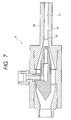
- Fig. 7 is a longitudinal cross section of a variation of the second embodiment of Fig. 5.
- a passage 54 downstream of a minimum diameter portion 53 of an ejection nozzle portion 52 is formed of a straight tube portion 55 with a constant inner diameter.
- the cleaning nozzle 51 of this embodiment also has a gas-liquid mixing action, similar to that of the previous embodiment, in the trumpet-shaped portion upstream of the minimum diameter portion 53 and thus can generate uniform droplets.
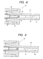
- Fig. 8 is a partial longitudinal cross section showing an essential part of still another embodiment of the invention.
- the trumpet-shaped portion of an ejection nozzle portion 57 is formed of two tapered portions 58, 59.
- a minimum diameter portion 60 located downstream of the trumpet-shaped portion is formed of a straight tube of a predetermined length. Downstream of the minimum diameter portion 60 is formed a passage having a tapered portion 61.
- Fig. 9 is a partial longitudinal cross section showing a variation of the embodiment of Fig. 8.
- a cleaning nozzle 65 of this embodiment has a straight tube portion 68 of a constant diameter downstream of a minimum diameter portion 67 of an ejection nozzle portion 66, instead of the tapered portion 61.
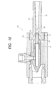
- Fig. 10 is a longitudinal cross section of a further embodiment of this invention.
- Fig. 11 is a partial, enlarged cross section showing an essential part of Fig. 10.
- a cleaning nozzle 69 of this embodiment is characterized in that the trumpet-shaped portion at the upstream end of an ejection nozzle portion 70 is formed by a curved surface portion 71, that a minimum diameter portion 72 is formed at the downstream end of the trumpet-shaped portion, and that a downstream-expanding tapered portion 73 is formed downstream of the minimum diameter portion 72.
- the cleaning liquid ejection portion 74 may also use a curved surface as its outer surface, rather than the tapered portions 75, 76.
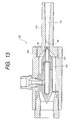
- Fig. 12 is a longitudinal cross section of a variation of the embodiment of Fig. 10.
- a cleaning nozzle 78 of this embodiment uses, instead of the tapered portion 73, a straight tube portion 81 of a constant inner diameter for the passage downstream of a minimum diameter portion 80 of an ejection nozzle portion 79.
- This construction can also produce the similar gas-liquid mixing action to that of the previous embodiment.
- Fig. 13 shows a longitudinal cross section of a further embodiment of this invention.
- Fig. 14 is an enlarged view of an essential part of Fig. 13.
- a gas ej ection port 149 is formed between two tapered portions 144, 145 formed on an outer surface of a cleaning liquid ejection portion 143 and a trumpet-shaped portion defined by two tapered portions 147, 148 formed at an upstream part of a conversing-diverging nozzle portion 146 so that the cross-sectional area of the passage decreases progressively.
- the gas is ejected at high speed from the gas ejection port 149 between the tapered portion 145 and the tapered portion 148.
- the high-speed pressurized gas ejected from the gas ejection port 149 is accelerated at the trumpet-shaped portion as it is mixed with the cleaning liquid ej ected from an ej ection port 150 of the cleaning liquid ej ection portion 143.
- the mixed gas-liquid flow is also subjected to accelerating and mixing actions of a tapered portion 152 downstream of a minimum diameter portion 151 of the conversing-diverging nozzle portion 146.
- Fig. 15 shows still another embodiment of a circuit for preventing clogging due to powder.
- This embodiment is a variation of the configuration shown in Fig. 2.
- This configuration when compared with the previous configuration, is characterized in that the cleaning liquid supply circuit including a cleaning liquid tank 14 and a pump 15 is also used as a liquid supply circuit for preventing the clogging due to powder. That is, an appropriate cleaning liquid such as water is supplied to the cleaning nozzle 10 and also supplied as a clogging prevention liquid through a branch pipe 82 to an intermediate pressure gas flow passage between a powder injection portion connected to the powder feeding device 17 and the cleaning nozzle 10.
- reference number 83 denotes a check valve for backflowprevention and 84 a valve.
- the clogging prevention liquid is supplied through the branch pipe 82 to prevent the powder from adhering to the inner wall surface, particularly protrusions and stepped portions, of passages in devices such as the cleaning nozzle 10 and from clogging the passages. It is possible to make setting such that after the powder injection into the pressurized gas flow has stopped, the clogging prevention liquid continues to be supplied for a predetermined period to remove the residual powder. In that case, it is of course possible to install a valve (not shown) parallelly with the valve 84 in an intermediate portion of the cleaning liquid supply circuit between the cleaning nozzle 10 and a connection with the branch pipe 82.
- the pump 19 of Fig. 2 may be omitted, as described in Unexamined Japanese Patent Publication No. Sho. 63-212469 for example, by utilizing the inner pressure of the pressurized gas flow itself in injecting the cloggingprevention liquid.
- the adj ustment of the amount of the clogging prevention liquid can be made by the valve 20 or valve 84. In that case, the liquid may be supplied not just in a constant supply mode but also in an intermittent mode if necessary.
- An experiment was conducted to remove graffiti on a concrete wall by using sodium hydrogencarbonate particles as a powder material.
- the present invention provides the following advantages.
- a first aspect of the invention relates to a cleaning nozzle, comprising an ejection nozzle portion having a minimum diameter portion and a trumpet-shapedportion formed by multiple inclined portions located upstream of said minimum diameter portion; a gas ejection port formed along said multiple inclined portions and opened to an intermediate part of said trumpet-shaped portion; another inclined portion having its inclination angle with respect to an axis of said ejection nozzle portion smaller than an ej ection angle of said gas ejection port and interposed between said gas ej ectionport and said minimum diameter portion; and a cleaning liquid ejection port formed inside said gas ejection port; whereby a gas is ejected from said gas ejection port at a speed higher than that of a cleaning liquid from said cleaning liquid ejection port to transform the cleaning liquid into droplets and to accelerate them.
- the invention according to the first aspect is particularly advantageous, when a gas jet flow passing through a central part of said gas ej ection port converges at a point upstream of said minimum diameter portion.
- the invention according to the first aspect can also be advantageously implemented, when a cross-sectional area of said gas ejection port perpendicular to a direction of its axis is progressively reduced toward its downstream open end to accelerate the gas.
- the invention according to the first aspect can further be improved, when a cross-sectional area of said gas ejection port at its downstream open end is set almost equal to or slightly smaller than that of said minimum diameter portion.
- the invention according to the first aspect is particularly favourable in a configuration, wherein a ratio between a cross-sectional area of said gas ejection port at its downstream open end and a cross-sectional area of the minimum diameter portion is set to 1:1 to 1:1.3.
- the invention according to the first aspect turned out to be very favourable, when a distance from said cleaning liquid ejection port to a downstream end of said ejection nozzle portion is 10-50 times a diameter of said minimum diameter portion.
- the invention according to the first aspect is further particularly favourable in a configuration, wherein a powder material can be supplied to an upstream side of said gas ejection port.
- a second aspect of the invention relates to a cleaning nozzle comprising:
- the invention according to the second aspect is particularly advantageous, when a gas jet flow passing through a central part of said gas ej ection port converges at a point upstream of said minimum diameter portion.
- the invention according to the second aspect can further be improved, when a cross-sectional area of said gas ejection port at its downstream open end is set almost equal to or slightly smaller than that of said minimum diameter portion.
- the invention according to the second aspect turned out to be very favourable, when a distance from said cleaning liquid ejection port to a downstream end of said ejection nozzle portion is 10-50 times a diameter of said minimum diameter portion.
- the third aspect of the invention relates to a cleaning nozzle comprising:
Landscapes
- Engineering & Computer Science (AREA)
- Mechanical Engineering (AREA)
- Nozzles (AREA)
- Cleaning By Liquid Or Steam (AREA)
Applications Claiming Priority (7)
| Application Number | Priority Date | Filing Date | Title |
|---|---|---|---|
| JP2000199750A JP5105569B2 (ja) | 2000-06-30 | 2000-06-30 | 洗浄ノズル |
| JP2000199750 | 2000-06-30 | ||
| JP2000199749 | 2000-06-30 | ||
| JP2000199749 | 2000-06-30 | ||
| JP2000363890 | 2000-11-29 | ||
| JP2000363890A JP2002079145A (ja) | 2000-06-30 | 2000-11-29 | 洗浄ノズル及び洗浄装置 |
| EP01115954A EP1166883B1 (fr) | 2000-06-30 | 2001-06-29 | Buse et appareil de nettoyage |
Related Parent Applications (1)
| Application Number | Title | Priority Date | Filing Date |
|---|---|---|---|
| EP01115954A Division EP1166883B1 (fr) | 2000-06-30 | 2001-06-29 | Buse et appareil de nettoyage |
Publications (2)
| Publication Number | Publication Date |
|---|---|
| EP1470865A2 true EP1470865A2 (fr) | 2004-10-27 |
| EP1470865A3 EP1470865A3 (fr) | 2009-02-18 |
Family
ID=27343939
Family Applications (2)
| Application Number | Title | Priority Date | Filing Date |
|---|---|---|---|
| EP04017546A Withdrawn EP1470865A3 (fr) | 2000-06-30 | 2001-06-29 | Buse et appareil de nettoyage |
| EP01115954A Expired - Lifetime EP1166883B1 (fr) | 2000-06-30 | 2001-06-29 | Buse et appareil de nettoyage |
Family Applications After (1)
| Application Number | Title | Priority Date | Filing Date |
|---|---|---|---|
| EP01115954A Expired - Lifetime EP1166883B1 (fr) | 2000-06-30 | 2001-06-29 | Buse et appareil de nettoyage |
Country Status (5)
| Country | Link |
|---|---|
| US (1) | US6935576B2 (fr) |
| EP (2) | EP1470865A3 (fr) |
| KR (1) | KR100553781B1 (fr) |
| DE (1) | DE60113770T2 (fr) |
| TW (1) | TW506856B (fr) |
Families Citing this family (44)
| Publication number | Priority date | Publication date | Assignee | Title |
|---|---|---|---|---|
| GB0100756D0 (en) | 2001-01-11 | 2001-02-21 | Powderject Res Ltd | Needleless syringe |
| DE20201338U1 (de) * | 2002-01-29 | 2003-06-05 | J. Wagner AG, Altstätten | Elektrostatische Pulversprühvorrichtung |
| EP1606755A4 (fr) * | 2003-03-25 | 2007-01-03 | Tradeweb Group L L C | Procede et systeme de mise en oeuvre d'un traitement direct de commerces de differents instruments financiers |
| WO2005063443A1 (fr) * | 2003-12-26 | 2005-07-14 | Bridgestone Corporation | Procedes de traitement de surface de roue en aluminium |
| US20050145270A1 (en) * | 2003-12-31 | 2005-07-07 | Ray R. K. | Pressure washer with injector |
| WO2006099857A2 (fr) * | 2005-03-23 | 2006-09-28 | Bauer, Andreas | Tete de pulverisation |
| US7611071B2 (en) * | 2006-04-24 | 2009-11-03 | Illinois Tool Works Inc. | Intermittently operable recirculating control module and dispensing nozzle having internally disposed fixed orifice |
| KR100795548B1 (ko) * | 2006-07-20 | 2008-01-21 | 주식회사 케이씨텍 | 노즐 세정 장치 및 이를 포함하는 슬릿 코터 |
| GB0708758D0 (en) | 2007-05-04 | 2007-06-13 | Powderject Res Ltd | Particle cassettes and process thereof |
| GB2454228B (en) * | 2007-11-01 | 2011-08-03 | Rapro Emulations Ltd | Shower head and shower apparatus |
| KR100922339B1 (ko) * | 2007-12-14 | 2009-10-21 | (주)플라즈마텍 | 전기집진방식을 이용한 미세입자 포집장치용 미세 분무장치 |
| US20090217947A1 (en) * | 2008-02-29 | 2009-09-03 | Wiederin Daniel R | Nebulizer rinse system and method of use |
| JP5058100B2 (ja) * | 2008-08-22 | 2012-10-24 | 川崎重工業株式会社 | 高圧洗浄液噴射式洗浄装置 |
| DE202009018911U1 (de) * | 2009-02-16 | 2014-07-08 | Jens-Werner Kipp | Reinigungsvorrichtung für die Reinigung empfindlicher Oberflächen |
| US8276680B2 (en) * | 2009-08-19 | 2012-10-02 | Raytheon Company | Methods and apparatus for providing emergency fire escape path |
| DE102010051227A1 (de) | 2010-11-12 | 2012-05-16 | Dental Care Innovation Gmbh | Düse zur Abstrahlung von flüssigen Reinigungsmitteln mit darin dispergierten abrasiven Partikeln |
| GB201021881D0 (en) * | 2010-12-23 | 2011-02-02 | Profibrix Bv | Powder delivery device |
| EP2554273A1 (fr) * | 2011-08-02 | 2013-02-06 | Omya Development AG | Dispositif de buse d'atomisation et son utilisation |
| JP5323898B2 (ja) * | 2011-08-01 | 2013-10-23 | シャープ株式会社 | 液体吐出ノズル、及び液体吐出ノズルにおける撥水層の再生方法 |
| DE102012111552A1 (de) * | 2012-11-28 | 2014-05-28 | Krones Ag | Füllorgan zum Befüllen eines Behälters mit einem Füllprodukt |
| CN103008299A (zh) * | 2012-11-30 | 2013-04-03 | 北京七星华创电子股份有限公司 | 一种气液两相雾化清洗装置及清洗方法 |
| CN102966963A (zh) * | 2012-12-19 | 2013-03-13 | 中国船舶重工集团公司第七�三研究所 | 一种锅炉受热面外部清洗喷射器 |
| CA2813099C (fr) | 2013-03-15 | 2021-11-23 | Belanger Inc. | Element de lavage pour vehicules produisant des bulles |
| CN103195464A (zh) * | 2013-04-16 | 2013-07-10 | 天津理工大学 | 一种用于防治煤矿工作面煤尘的泡沫溶胶技术的应用装备 |
| DE102013009708B4 (de) * | 2013-06-10 | 2018-01-11 | Jt-Elektronik Gmbh | Spülkopf für Abwasserkanäle und Zuführung von Medien |
| WO2015059941A1 (fr) * | 2013-10-21 | 2015-04-30 | 株式会社不二製作所 | Méthode d'usinage par sablage et dispositif d'usinage par sablage |
| US9056322B1 (en) * | 2014-03-27 | 2015-06-16 | Jack Williams | Fluid jet apparatus |
| US11383349B2 (en) * | 2014-08-20 | 2022-07-12 | Oceanit Laboratories, Inc. | Reduced noise abrasive blasting systems |
| KR101633274B1 (ko) * | 2015-10-21 | 2016-06-24 | 주식회사 위그린 | 공기소독장치에 구비되는 증발챔버 |
| DE102016106052A1 (de) * | 2015-11-10 | 2017-05-11 | Sms Group Gmbh | Venturi-Düse, Pulvereinblasvorrichtung sowie Verfahren zum Betrieb einer Pulvereinblasvorrichtung |
| CN106392900A (zh) * | 2016-12-08 | 2017-02-15 | 贵州大学 | 喷砂机的双曲线喷嘴 |
| USD825741S1 (en) | 2016-12-15 | 2018-08-14 | Water Pik, Inc. | Oral irrigator handle |
| CN110730641B (zh) | 2017-03-16 | 2022-03-25 | 洁碧有限公司 | 用于与口腔试剂一起使用的口腔冲洗器手柄 |
| EP3607911B1 (fr) * | 2018-08-09 | 2021-04-07 | Ferton Holding S.A. | Système de buse et dispositif de projection de poudre |
| US12280468B2 (en) * | 2018-12-11 | 2025-04-22 | Kennametal Inc. | Method and design for productive quiet abrasive blasting nozzles |
| GB201905215D0 (en) * | 2019-04-12 | 2019-05-29 | Rolls Royce Plc | A method and apparatus for finishing a surface of a component |
| CN110314776B (zh) * | 2019-08-02 | 2024-06-21 | 中国人民解放军96771部队 | 一种可自清洗喷头 |
| CN110694985A (zh) * | 2019-10-22 | 2020-01-17 | 河南恒安电力股份有限公司 | 气液砂混合高压带电清洗系统 |
| CN110665667A (zh) * | 2019-11-14 | 2020-01-10 | 南京鹏昆环保科技有限公司 | 一种气粉混合的复合型喷嘴 |
| GB202005441D0 (en) | 2020-04-14 | 2020-05-27 | Kelda Showers Ltd | Shower head and method of operation to produce a suspension of water droplets in air |
| CN112922276B (zh) * | 2021-01-18 | 2022-12-06 | 四川省第一建筑工程有限公司 | 一种操作方便的腻子喷涂设备 |
| CN112793034B (zh) * | 2021-01-18 | 2022-12-06 | 宣城七彩塑胶制品有限公司 | 一种防止塑料颗粒炭化引起堵塞的塑料造粒机 |
| CN116982743A (zh) * | 2022-04-25 | 2023-11-03 | 深圳市卓力能技术有限公司 | 一种雾化器 |
| DE102022124763A1 (de) * | 2022-09-27 | 2024-03-28 | Khs Gmbh | Düse mit konischem Strömungskanal |
Citations (3)
| Publication number | Priority date | Publication date | Assignee | Title |
|---|---|---|---|---|
| JPS60261566A (ja) | 1984-06-11 | 1985-12-24 | Osamu Oya | 噴射装置 |
| JPS63212469A (ja) | 1987-02-24 | 1988-09-05 | Eikichi Yamaharu | ブラスト装置 |
| JPH10156229A (ja) | 1996-12-02 | 1998-06-16 | Mitsubishi Electric Corp | 洗浄用2流体ジェットノズル及び洗浄装置 |
Family Cites Families (15)
| Publication number | Priority date | Publication date | Assignee | Title |
|---|---|---|---|---|
| DE1036497B (de) | 1954-07-30 | 1958-08-14 | Cie Parisienne D Outil A Air C | Spritzduese fuer Moertel od. dgl. |
| US4134547A (en) * | 1976-12-14 | 1979-01-16 | O. Ditlev-Simonsen, Jr. | Jet pipe |
| JPS5665654A (en) * | 1979-10-31 | 1981-06-03 | Kyocera Corp | Apparatus for generating water droplets containing gas bubbles |
| JPS5665655A (en) * | 1979-10-31 | 1981-06-03 | Kyocera Corp | Apparatus for generating water droplets containing gas bubbles |
| US4787404A (en) * | 1987-06-12 | 1988-11-29 | International Business Machines Corporation | Low flow rate-low pressure atomizer device |
| US4817342A (en) | 1987-07-15 | 1989-04-04 | Whitemetal Inc. | Water/abrasive propulsion chamber |
| WO1990011877A1 (fr) | 1989-03-31 | 1990-10-18 | Aliva Aktiengesellschaft | Convertisseur de jets de beton |
| DE4120613A1 (de) | 1991-06-20 | 1992-03-05 | Suesse Harald | Selbstregulierender hochdrucktrennstrahlbeschleuniger |
| SE505253C2 (sv) | 1993-06-11 | 1997-07-21 | Fredrik Hedin | Sätt och anordning för bildande av snö |
| JP2728847B2 (ja) | 1993-07-23 | 1998-03-18 | 日本パーカライジング株式会社 | 粉体流量測定方法およびその装置 |
| US5509849A (en) * | 1994-04-18 | 1996-04-23 | Church & Dwight Co., Inc. | Blast nozzle for water injection and method of using same for blast cleaning solid surfaces |
| KR100312705B1 (ko) * | 1994-06-29 | 2002-02-19 | 박종석 | 급수관등의내부세정장치 |
| US5520331A (en) * | 1994-09-19 | 1996-05-28 | The United States Of America As Represented By The Secretary Of The Navy | Liquid atomizing nozzle |
| US5732885A (en) * | 1994-10-07 | 1998-03-31 | Spraying Systems Co. | Internal mix air atomizing spray nozzle |
| JP3410385B2 (ja) * | 1999-04-19 | 2003-05-26 | 株式会社ディスコ | 洗浄装置及び切削装置 |
-
2001
- 2001-06-29 EP EP04017546A patent/EP1470865A3/fr not_active Withdrawn
- 2001-06-29 TW TW090115925A patent/TW506856B/zh not_active IP Right Cessation
- 2001-06-29 EP EP01115954A patent/EP1166883B1/fr not_active Expired - Lifetime
- 2001-06-29 US US09/894,008 patent/US6935576B2/en not_active Expired - Lifetime
- 2001-06-29 DE DE60113770T patent/DE60113770T2/de not_active Expired - Lifetime
- 2001-06-29 KR KR1020010038071A patent/KR100553781B1/ko not_active Expired - Fee Related
Patent Citations (3)
| Publication number | Priority date | Publication date | Assignee | Title |
|---|---|---|---|---|
| JPS60261566A (ja) | 1984-06-11 | 1985-12-24 | Osamu Oya | 噴射装置 |
| JPS63212469A (ja) | 1987-02-24 | 1988-09-05 | Eikichi Yamaharu | ブラスト装置 |
| JPH10156229A (ja) | 1996-12-02 | 1998-06-16 | Mitsubishi Electric Corp | 洗浄用2流体ジェットノズル及び洗浄装置 |
Non-Patent Citations (1)
| Title |
|---|
| "Mechanical Engineering Handbook", vol. A5, 15 April 1987, JAPAN MECHANICAL ENGINEERS ASSOCIATION, pages: 58 |
Also Published As
| Publication number | Publication date |
|---|---|
| EP1470865A3 (fr) | 2009-02-18 |
| EP1166883A3 (fr) | 2003-10-22 |
| TW506856B (en) | 2002-10-21 |
| DE60113770D1 (de) | 2006-02-16 |
| DE60113770T2 (de) | 2006-06-08 |
| KR100553781B1 (ko) | 2006-02-20 |
| KR20020002300A (ko) | 2002-01-09 |
| EP1166883B1 (fr) | 2005-10-05 |
| US20020000477A1 (en) | 2002-01-03 |
| EP1166883A2 (fr) | 2002-01-02 |
| US6935576B2 (en) | 2005-08-30 |
Similar Documents
| Publication | Publication Date | Title |
|---|---|---|
| US6935576B2 (en) | Cleaning nozzle and cleaning apparatus | |
| US10245602B2 (en) | Atomizer nozzle | |
| KR20080013757A (ko) | 동역학적 분무 시스템용 노즐 조립체와, 동역학적 분무시스템에 의해 도포된 분말로 기재를 코팅하는 방법 | |
| JP2713814B2 (ja) | 圧縮性流体用エジェクタ | |
| US20150129171A1 (en) | Method and apparatus for cleaning surfaces of a finned heat exchanger | |
| JPH07194995A (ja) | 低空気圧作動スプレイノズル | |
| JP2006247639A (ja) | コールドスプレー用ノズルならびにこれを利用したコールドスプレー装置及び方法 | |
| CN111207414A (zh) | 强旋流离心回流式喷嘴 | |
| JP6990848B2 (ja) | 噴射ノズルおよび噴射方法 | |
| JP2002079145A (ja) | 洗浄ノズル及び洗浄装置 | |
| KR100565815B1 (ko) | 기체액체 혼합류 분사장치 | |
| KR102649754B1 (ko) | 제트 펌프 | |
| KR100776194B1 (ko) | 콜드 스프레이용 노즐 및 이를 이용한 콜드 스프레이 장치 | |
| JP6865952B2 (ja) | 1流体ノズル | |
| JP2005279562A (ja) | マイクロミスト発生方法及びその装置 | |
| JPH0623670A (ja) | ウオータジェット切断用ノズル及びウオータジェットによる切断方法 | |
| JP5105569B2 (ja) | 洗浄ノズル | |
| JP4575017B2 (ja) | 固気混合エジェクタおよびジェットミル | |
| JP4246550B2 (ja) | 噴射ノズル | |
| CN113400205B (zh) | 一种带有清洁功能的脉冲式喷头装置 | |
| JP2002102809A (ja) | キャビテーションジェットノズル | |
| KR100776537B1 (ko) | 콜드 스프레이용 노즐 및 이를 이용한 콜드 스프레이 장치 | |
| JPH05202826A (ja) | 燃料噴射ノズル | |
| JPS60213626A (ja) | 多段推力発生方法及び装置 | |
| JPS60147005A (ja) | 減圧・減温装置 |
Legal Events
| Date | Code | Title | Description |
|---|---|---|---|
| PUAI | Public reference made under article 153(3) epc to a published international application that has entered the european phase |
Free format text: ORIGINAL CODE: 0009012 |
|
| AC | Divisional application: reference to earlier application |
Ref document number: 1166883 Country of ref document: EP Kind code of ref document: P |
|
| AK | Designated contracting states |
Kind code of ref document: A2 Designated state(s): DE FR GB IT |
|
| PUAL | Search report despatched |
Free format text: ORIGINAL CODE: 0009013 |
|
| AK | Designated contracting states |
Kind code of ref document: A3 Designated state(s): DE FR GB IT |
|
| 17P | Request for examination filed |
Effective date: 20090430 |
|
| 17Q | First examination report despatched |
Effective date: 20090529 |
|
| RIC1 | Information provided on ipc code assigned before grant |
Ipc: B24C 5/02 20060101ALI20090831BHEP Ipc: B05B 15/02 20060101ALI20090831BHEP Ipc: B05B 7/14 20060101ALI20090831BHEP Ipc: B24C 5/04 20060101ALI20090831BHEP Ipc: B05B 7/04 20060101AFI20090831BHEP Ipc: B24C 7/00 20060101ALI20090831BHEP |
|
| RTI1 | Title (correction) |
Free format text: CLEANING APPARATUS |
|
| AKX | Designation fees paid |
Designated state(s): DE FR GB IT |
|
| STAA | Information on the status of an ep patent application or granted ep patent |
Free format text: STATUS: THE APPLICATION IS DEEMED TO BE WITHDRAWN |
|
| 18D | Application deemed to be withdrawn |
Effective date: 20100304 |