EP1470867A2 - Sprühvorrichtung mit einem auswechselbaren Produktbehälter - Google Patents
Sprühvorrichtung mit einem auswechselbaren Produktbehälter Download PDFInfo
- Publication number
- EP1470867A2 EP1470867A2 EP04291044A EP04291044A EP1470867A2 EP 1470867 A2 EP1470867 A2 EP 1470867A2 EP 04291044 A EP04291044 A EP 04291044A EP 04291044 A EP04291044 A EP 04291044A EP 1470867 A2 EP1470867 A2 EP 1470867A2
- Authority
- EP
- European Patent Office
- Prior art keywords
- product
- reservoir
- spraying
- partition
- passage
- Prior art date
- Legal status (The legal status is an assumption and is not a legal conclusion. Google has not performed a legal analysis and makes no representation as to the accuracy of the status listed.)
- Withdrawn
Links
Images

Classifications
-
- A—HUMAN NECESSITIES
- A01—AGRICULTURE; FORESTRY; ANIMAL HUSBANDRY; HUNTING; TRAPPING; FISHING
- A01G—HORTICULTURE; CULTIVATION OF VEGETABLES, FLOWERS, RICE, FRUIT, VINES, HOPS OR SEAWEED; FORESTRY; WATERING
- A01G9/00—Cultivation in receptacles, forcing-frames or greenhouses; Edging for beds, lawn or the like
- A01G9/12—Supports for plants; Trellis for strawberries or the like
- A01G9/122—Stakes
-
- B—PERFORMING OPERATIONS; TRANSPORTING
- B05—SPRAYING OR ATOMISING IN GENERAL; APPLYING FLUENT MATERIALS TO SURFACES, IN GENERAL
- B05B—SPRAYING APPARATUS; ATOMISING APPARATUS; NOZZLES
- B05B7/00—Spraying apparatus for discharge of liquids or other fluent materials from two or more sources, e.g. of liquid and air, of powder and gas
- B05B7/24—Spraying apparatus for discharge of liquids or other fluent materials from two or more sources, e.g. of liquid and air, of powder and gas with means, e.g. a container, for supplying liquid or other fluent material to a discharge device
- B05B7/2402—Apparatus to be carried on or by a person, e.g. by hand; Apparatus comprising containers fixed to the discharge device
- B05B7/2405—Apparatus to be carried on or by a person, e.g. by hand; Apparatus comprising containers fixed to the discharge device using an atomising fluid as carrying fluid for feeding, e.g. by suction or pressure, a carried liquid from the container to the nozzle
- B05B7/2416—Apparatus to be carried on or by a person, e.g. by hand; Apparatus comprising containers fixed to the discharge device using an atomising fluid as carrying fluid for feeding, e.g. by suction or pressure, a carried liquid from the container to the nozzle characterised by the means for producing or supplying the atomising fluid, e.g. air hoses, air pumps, gas containers, compressors, fans, ventilators, their drives
- B05B7/2421—Gas containers
-
- B—PERFORMING OPERATIONS; TRANSPORTING
- B05—SPRAYING OR ATOMISING IN GENERAL; APPLYING FLUENT MATERIALS TO SURFACES, IN GENERAL
- B05B—SPRAYING APPARATUS; ATOMISING APPARATUS; NOZZLES
- B05B7/00—Spraying apparatus for discharge of liquids or other fluent materials from two or more sources, e.g. of liquid and air, of powder and gas
- B05B7/02—Spray pistols; Apparatus for discharge
- B05B7/12—Spray pistols; Apparatus for discharge designed to control volume of flow, e.g. with adjustable passages
- B05B7/1209—Spray pistols; Apparatus for discharge designed to control volume of flow, e.g. with adjustable passages the controlling means for each liquid or other fluent material being manual and interdependent
-
- B—PERFORMING OPERATIONS; TRANSPORTING
- B05—SPRAYING OR ATOMISING IN GENERAL; APPLYING FLUENT MATERIALS TO SURFACES, IN GENERAL
- B05B—SPRAYING APPARATUS; ATOMISING APPARATUS; NOZZLES
- B05B7/00—Spraying apparatus for discharge of liquids or other fluent materials from two or more sources, e.g. of liquid and air, of powder and gas
- B05B7/24—Spraying apparatus for discharge of liquids or other fluent materials from two or more sources, e.g. of liquid and air, of powder and gas with means, e.g. a container, for supplying liquid or other fluent material to a discharge device
- B05B7/2402—Apparatus to be carried on or by a person, e.g. by hand; Apparatus comprising containers fixed to the discharge device
- B05B7/2405—Apparatus to be carried on or by a person, e.g. by hand; Apparatus comprising containers fixed to the discharge device using an atomising fluid as carrying fluid for feeding, e.g. by suction or pressure, a carried liquid from the container to the nozzle
- B05B7/2408—Apparatus to be carried on or by a person, e.g. by hand; Apparatus comprising containers fixed to the discharge device using an atomising fluid as carrying fluid for feeding, e.g. by suction or pressure, a carried liquid from the container to the nozzle characterised by the container or its attachment means to the spray apparatus
-
- B—PERFORMING OPERATIONS; TRANSPORTING
- B05—SPRAYING OR ATOMISING IN GENERAL; APPLYING FLUENT MATERIALS TO SURFACES, IN GENERAL
- B05B—SPRAYING APPARATUS; ATOMISING APPARATUS; NOZZLES
- B05B7/00—Spraying apparatus for discharge of liquids or other fluent materials from two or more sources, e.g. of liquid and air, of powder and gas
- B05B7/24—Spraying apparatus for discharge of liquids or other fluent materials from two or more sources, e.g. of liquid and air, of powder and gas with means, e.g. a container, for supplying liquid or other fluent material to a discharge device
- B05B7/2402—Apparatus to be carried on or by a person, e.g. by hand; Apparatus comprising containers fixed to the discharge device
- B05B7/2405—Apparatus to be carried on or by a person, e.g. by hand; Apparatus comprising containers fixed to the discharge device using an atomising fluid as carrying fluid for feeding, e.g. by suction or pressure, a carried liquid from the container to the nozzle
- B05B7/2429—Apparatus to be carried on or by a person, e.g. by hand; Apparatus comprising containers fixed to the discharge device using an atomising fluid as carrying fluid for feeding, e.g. by suction or pressure, a carried liquid from the container to the nozzle the carried liquid and the main stream of atomising fluid being brought together after discharge
-
- B—PERFORMING OPERATIONS; TRANSPORTING
- B05—SPRAYING OR ATOMISING IN GENERAL; APPLYING FLUENT MATERIALS TO SURFACES, IN GENERAL
- B05B—SPRAYING APPARATUS; ATOMISING APPARATUS; NOZZLES
- B05B7/00—Spraying apparatus for discharge of liquids or other fluent materials from two or more sources, e.g. of liquid and air, of powder and gas
- B05B7/24—Spraying apparatus for discharge of liquids or other fluent materials from two or more sources, e.g. of liquid and air, of powder and gas with means, e.g. a container, for supplying liquid or other fluent material to a discharge device
- B05B7/2402—Apparatus to be carried on or by a person, e.g. by hand; Apparatus comprising containers fixed to the discharge device
- B05B7/2478—Gun with a container which, in normal use, is located above the gun
Definitions
- the present invention relates to devices for spraying a product, in particular cosmetic, for example a liquid foundation.
- Spraying with an airbrush allows in particular to make less visible a border between treated and untreated skin areas, to fade or gradients.
- the make-up gesture is also different, since the product that is sprayed does not have to be spread once deposited.
- the application of the product is thus very hygienic, since it can be done without fingers and without an applicator.
- a disadvantage of the known devices is that it is relatively difficult to just add the desired amount of product.
- the invention aims to further improve the spraying devices in order to facilitate the creation of neat makeup.
- the invention aims in particular to meet this need.
- the user can easily make up with several products with different colors, using the same spraying mechanism, by interchanging the tanks containing these products if necessary.
- the risk of leakage product is limited by the fact that as soon as the tank is removed, the product outlet passage closes automatically.
- the reservoir comprises at minus a first partition and first and second compartments capable of contain the product, these compartments being arranged to supply product with the spraying mechanism and being arranged on either side of the first partition.
- bulkhead is to be understood broadly and includes in particular solid, hollow, perforated, rigid, flexible, porous, flat walls, cylindrical or having other shapes, which can in particular be formed by the juxtaposition of obstacles to the flow of the product.
- the reservoir and the device can be arranged to allow the attachment of the tank on the device near the outlet of the product which is sprayed, this which can allow, if it is desirable, to convey the product more quickly to the outlet and reduce the volume of product which remains inside the device, outside the tank, between two uses.
- the aforementioned passage, through which the product flows out of the tank can in particular lead, at one end, on either side of the first partition, the first and second compartments communicating together through said passage.
- the shutter may include a ball valve.
- the spraying mechanism may then include a relief arranged to move the ball from a closed position to a position opening the passage, when the reservoir is put in place.
- the tank may have at least a second partition on one side of the first, associated with the first compartment and delimiting therein two sub-compartments communicating with each other.
- the tank may also include at minus a third partition associated with the second compartment and delimiting therein two sub-compartments, the first aforementioned partition being located between the second and third partitions.
- the reservoir may include a base part and a cover part, reported on the basic part.
- the second and third partitions can then be made in one piece with at least one of the base part and the forming part lid.
- the reservoir may have a generally elongated shape, with a longitudinal axis substantially parallel to the direction in which the spraying takes place.
- the passage from the reservoir through which the product is delivered to the mechanism can be at least partially delimited by a tip. This can be salient.
- the tip can wear an O-ring seal.
- the reservoir may be at least partially transparent, in order to allow the user to observe the level and color of the product.
- the reservoir may further comprise a fixing part arranged for cooperate by complementarities of forms with the spraying mechanism.
- the reservoir may also include a micro-opening opening to the air free.
- the spraying mechanism may include a housing for receiving a carrier gas reserve, the product being sprayed thanks to a vacuum created by a flow of this carrier gas.
- the latter can be stored in a liquefied form in a pressurized container.
- a movable cover can close the access to the housing.
- the spraying mechanism may include a control member arranged so as to act simultaneously both on a carrier gas distribution valve and on a valve for adjusting the flow rate of the sprayed product.
- the adjustment valve comprises a needle arranged to cooperate with an associated seat, so that the product flow spray varies with the distance between the seat and the needle.
- Such an adjustment valve allows the user to gradually and precisely adjust the quantity of product sprayed.
- the control member may include a rotary lever.
- the dispensing valve can be integral with the pressurized container, which allows to benefit from an economy of scale in its realization and in particular to use a conventional dispensing valve, triggered by tilting a rod ordered.
- the seat can be located on a support piece of at least one nozzle spraying the product.
- This support piece can be made of plastic. She can be removably attached to the device.
- the device comprises two outlet nozzles from the carrier gas and an outlet nozzle for the product to be sprayed.
- Each nozzle can be metallic.
- the device may in particular comprise two outlet ports for carrier gas having axes converging away from the device, and the product outlet can have an axis located substantially in the same plane as the axes of the outlet orifices carrier gas. This allows in particular to obtain a relatively soft spray and good application conditions.
- the needle slides in a direction substantially parallel to the direction in which the product is sprayed.
- the device may include a needle return spring in a rest position in which it applies against the seat. If necessary, the control member is devoid of its own return spring.
- the device may include a tip arranged to engage on a rod.
- control of the dispensing valve and the control member can be arranged to be able to apply against this tip.
- a mirror can be hinged on the spray mechanism to allow the user to observe the area on which the product is sprayed.
- the spray mechanism may have a generally elongated shape and the control member present a bearing face for the user, arranged on one side longitudinal of the device.
- the latter may also, alternatively, have the form general of a pistol.
- the control member may have a support face for the user, arranged on one side of a stick, this side being located opposite to an orifice from which the product that is sprayed. This stock can accommodate the pressurized container.
- the product tank and the pressurized container can be fixedly linked, without displacement of one relative to the other during use.
- the product which is sprayed can be a liquid, a powder, a product cosmetic, in particular a foundation.
- the subject of the invention is also, independently or in combination with this above, a device for spraying at least one product contained in a tank, in particular a cosmetic product, the product being taken from the tank thanks to a vacuum created at an outlet opening of the tank by a flow of a carrier gas, this carrier gas being stored in a pressurized container, this device comprising a valve for adjusting the flow rate of sprayed product and a control capable of being operated by the user to act at the same time on a valve of distribution of the carrier gas and on the adjustment valve, the latter comprising a needle arranged to cooperate with an associated seat so that the product flow spray varies with the distance between the seat and the needle.
- the product flow can be gradually adjusted and precisely by the user, which facilitates obtaining quality makeup.
- control member has a rotary lever.
- a lever can be made if necessary with a length relatively large, so that it can be operated by the user without the latter have to exert a significant effort.
- the dispensing valve is preferably integral with the pressurized container. It can reduce the cost of the device by taking advantage of an economy of scale thanks to the use of a conventional dispensing valve, in particular triggered by tilting of a control rod.
- the seat is located on a support piece at least one product spray nozzle.
- This support piece can be in plastic and if necessary be removably attached to the device, which can facilitate its cleaning or allow the change of the nozzle (s) according to the desired spray geometry.
- the device may include two carrier gas outlet nozzles and an outlet nozzle for the product to be sprayed.
- the device may in particular comprise two vector gas outlet orifices having axes converging away from the device. This can provide a more spray soft.
- the product outlet may have an axis located substantially in the same plane as the axes of the carrier gas outlet ports.
- Each nozzle may be metallic and in particular be produced by bar turning. This allows to obtain in an economical way, in particular without having to invest in the production of molds, quality nozzles.
- the device is advantageously portable and autonomous, and includes a housing for receiving the pressurized container.
- the device may include a cover mobile, for example articulated, to close access to housing.
- the needle can slide in one direction substantially parallel to the direction in which the product is sprayed.
- the device may include a needle return spring in a rest position, in which it applies against the seat.
- the control member can thus be devoid of a spring its own reminder.
- the device may include a nozzle arranged to engage on a control rod of the dispensing valve and the control member can be arranged to be able to be applied against this tip when operated to initiate spraying.
- the device can include a mirror Speak clearly.
- the control unit can be positioned in various ways on the device.
- the device may have a generally elongated shape and the control may have a support face for the user arranged on one side longitudinal of the device. Such a provision may prove particularly ergonomic.
- the device can also have the general shape of a pistol.
- the organ of control can then have a support face for the user arranged on one side a stick, this side being for example located opposite an orifice from which the product comes out which is sprayed.
- the stock can accommodate the pressurized container.
- the product reservoir and the container pressurized are fixedly linked, without displacement of one relative to the other during use.
- the reservoir may include a micro-opening opening into the open air or a air return valve.
- the reservoir can be removably attached to the device.
- the product which is sprayed can be a liquid, a powder, a product cosmetic, in particular a foundation.
- the invention also relates to an assembly comprising a device such as defined above and a reservoir containing the product to be sprayed.
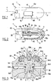
- the spraying device shown in Figures 1 and 2, includes a spraying mechanism 10 and a removable reservoir 20 containing the product to be spray, for example a liquid foundation.
- the mechanism 10 comprises a housing 11 formed for example by the assembly two plastic shells and a movable control member 12 making it possible to trigger spraying.
- the housing 11 has a generally elongated shape along a longitudinal axis X which is substantially parallel to a direction Y along which the product is sprayed by a spray head 30.
- the control member 12 has an upper face 12a on which user can press to cause distribution, and stretching, in the example considered, on the upper longitudinal side of the mechanism 10.
- the lever 12 is articulated around a pivot 19, fixed relative to the housing 11.
- the axis around which the command 12 pivots is for example orthogonal to the longitudinal axis X, and can cut this axis X.
- the control member 12 comprises two arms, the first defining the upper face 12a above and the second one end 12b whose role will be explained later.
- the housing 11 includes a housing 11a which receives a pressurized container 40 containing a carrier gas, for example butane, isobutane or isopropane or a liquefied fluorinated compound.
- a carrier gas for example butane, isobutane or isopropane or a liquefied fluorinated compound.
- This container 40 is equipped with a dispensing valve comprising a hollow control rod 41, this rod 41 actuating the valve when it is tilted.
- the container 40 can be introduced inside the housing 11 thanks to a cover removable 13.
- the control rod 41 engages in a nozzle 14 which cooperates with the control member 12, and in particular with the end 12b.
- the end piece 14 also opens into a tube 15 in which the gas contained in the pressurized container 40 escapes when the control rod 41 is tilted under the constraint of the control member 12.
- the tube 15 opens out at a guide assembly 16 in which can slide a needle 50, parallel to a Y axis, the latter being parallel or even coincident with the longitudinal axis X.
- the needle 50 can be driven in displacement by a rod 17 connected to a end 17a to the lever 12 and at the other end 17b to a lug 51 secured to the needle 50.
- the lug 51 slides in a slot 18 of the guide assembly 16.
- the spray head 30 comprises, in the example considered, two nozzles 31 and 32 for spraying gas vector and a nozzle 33 for spraying the product contained in the reservoir 20, these nozzles 31 to 33 being fixed on a common support piece 34, itself fixed on the assembly guide 16.
- the nozzles 31 to 33 are produced, in the example considered, by bar turning of a metal, and have a threaded portion 35 allowing their mounting on the workpiece support 34 and respective interior channels 31a, 32a and 33a.
- the respective axes V and W of the outlet orifices 31b and 32b of the nozzles 31 and 32 intersect in front of the nozzle 33 and form between them an angle ⁇ close to 90 ° in the example considered.
- the distance H, measured between the front face of the nozzle 33 and the nozzles 31 and 32, is approximately 1.7 mm in the example described.
- the diameter of the orifices 31b and 32b carrier gas outlet is for example 0.4 mm and that of the outlet port 33b of the 0.9 mm product.
- the support piece 34 has channels 34a and 34b communicating respectively with the channels 31a and 32a of the nozzles 31 and 32 at one end and at the other end with an annular groove 34c opening onto the rear face 34d of the piece of support 34.
- the latter has a sealing lip 34e which is applied against a surface of the guide assembly 16 as well as a threaded portion 34f which engages in a housing 16a of this assembly 16.
- the threaded portion 34f carries an O-ring sealing 37 which is applied sealingly on the wall of the housing 16a.
- a annular chamber 38 is formed between the support piece 34 and the guide assembly 16 and the carrier gas is conveyed in this annular chamber by a channel 16b of the assembly 16, this channel 16b communicating with the pipe 15.
- the support piece 34 defines a seat 34g of conical shape against which can be applied at rest the end 54, of the same conical shape, of the needle 50.
- a channel 34i of axis Y produced in the support piece 34 allows the product to be sprayed to gain the inner channel 33a of the nozzle 33 when the end 54 of the needle 50 is separated 34g seat.
- the needle 50 is biased against its seat by a helical spring 55 working in compression, housed in the guide assembly 16, partially visible on Figure 2, coming to bear at one end against a wall of the assembly 16 and at the other end against a shoulder of the needle 50.
- the operation of the device 1 is as follows.
- the user presses the face 12a of the lever 12 presses by its end 12b against the end piece 14, which causes the tilting of the control rod 41 and the emission of carrier gas.
- This the latter traverses in particular the end piece 14, the tubing 15, the channel 16b and the channels 34a and 34b before leaving the outlet orifices 31b and 32b of the nozzles 31 and 32.
- the lever 12 also moves the rod 17 and the needle 50 in displacement, whose end 54 deviates from seat 34g by a distance d which is proportional to the angle the lever 12 of which turns.
- the user can thus, by pressing the lever 12 more or less, adjust the flow rate of the product which is sucked into the tank 20.
- the movement of the lever 12 influences the flow rate of the gas released by the pressurized tank 40, and thus on the importance of the depression created by the flow of carrier gas at the outlet orifice 33b of the nozzle 33, which makes it possible to distribute more or less product on the treated surface.
- the device 1 can be provided, as seen in Figure 1, with a mirror articulated 60, the reflecting surface of which faces the housing 11 when the mirror is in folded position, as shown in figure 1.
- the user can rotate the mirror 60 a quarter of a turn and use it to follow the makeup which is made with the spraying device 1.
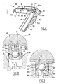
- the device 1 can be produced with other shapes than that illustrated in Figures 1 and 2, and in particular present a general form of pistol, as shown in Figure 4.
- pressurized container 40 can be housed in the pistol grip, the face 12a of the lever 12 serving to support the user being located on the side 11c of the stick which is opposite to the orifice through which the product is distributed.
- the longitudinal axis of the container makes an angle of about 60 ° with the Y axis.
- the control rod 41 is oriented, in the absence of spraying, as is can see it in figure 4, obliquely and to the right, the spraying being carried out towards the left.
- the reservoir 20 may be removably attached to the spraying mechanism 10, so that the user can replace it with a another once the product contained in it has been used up.
- This may include, as seen in Figure 5 in particular, a base part 21 and a cover 22 attached to the base part 21, both being fixed for example by gluing, welding or snap-fastening.
- the cover 22 is preferably made of a transparent material, of to allow the user to appreciate the filling level and the color of the product P contained inside.
- the cover 22 can be crossed by a micro-orifice 22d air intake, small enough to prevent the flow of product P through.
- the base part 21 is, in the example considered, made with a tip projection 23 intended to engage in a corresponding housing 70 produced on the mechanism spray 10, this housing 70 communicating through a conduit 71 with the space 16d in which the needle 50 slides.
- the end piece 23 carries an O-ring 24 which makes it possible to avoid product leaks once it is in place in the housing 70, as shown in FIG. 9.
- the end piece 23 After closing the tank before mounting it on mechanism 10, the end piece 23 internally houses a valve comprising a ball 25 and a spring 26 which can keep the ball 25 pressed against a corresponding seat 23a produced on the end piece 23, as can be seen in Figure 5.
- the ball 25 can move in a passage 23b inside the end piece 23, this passage 23b comprising at its periphery four longitudinal channels 23c allowing the product contained in the reservoir 20 bypassing the ball 25 and flowing towards the housing 70 once the ball 25 has been pushed out of its seat 23a.
- Move of the ball 25 can be caused by a relief 73 of the spraying mechanism 10, as can be seen in Figure 9.
- the ball 25 resumes its support against the seat 23a and closes so seals the passage 23b.
- the reservoir 20 has a generally elongated shape along a longitudinal axis Z which, in the embodiment of Figures 1 and 2, is substantially parallel to the axis longitudinal X and to the spraying direction Y.
- the Z axis is substantially parallel to the spray axis Y and forms with the axis longitudinal of the stock an angle of about 45 °.
- the inclination of the tank 20 may vary and, in accordance with a aspect of the invention, the reservoir 20 is produced so that the passage 23b is always supplied with product P.
- the reservoir is thus produced with means allowing to slow down the movement of the product in the tank, in this case several partitions, including a first partition 27 which delimits, inside the tank 20, first 20a and second 20b compartments containing product P.
- Each of these compartments is itself delimited into two sub-compartments by second 28 and third 29 partitions, respectively.
- These partitions 28 and 29 are produced, in the example considered, in one piece by molding of material plastic with the base part 21, the first partition 27 being made in one piece by molding material with the cover 22.
- the first partition 27 extends transversely, as can be seen in the Figure 6, across the width of the tank, while the second 28 and third 29 partitions provide with the cover 22 respective passages 20c and 20d, allowing the product to circulate on either side of said partitions in compartments 20a and 20b when the inclination of the reservoir 20, around a horizontal axis perpendicular to the Z axis, exchange.
- the partitions 28 and 29 thus slow down the flow of the product P without preventing it to gain passage 23b.
- the first partition 27 extends, inside the end piece 23, to form a guide 27a for the spring 26, as can be seen in FIG. 5.
- the first partition 27 is configured so that the two compartments 20a and 20b can be emptied independently of each other. It may not include any openings. Both compartments may not communicate otherwise than through passage 23b.
- the two compartments 20a and 20b can extend essentially each on the one hand and on the other side of a plane containing a longitudinal axis of the passage 23b.
- one of the compartments 20a, 20b can be empty without the other emptying.
- the reservoir 20 can be retained on the spraying mechanism 10 by the only friction created by the application of the O-ring 24 against the wall of the housing 70.
- additional fastening means are provided which may include for example a link with complementarities of shapes comprising for example a groove 74 in which a rib 75 in the form of a dovetail can engage.
- the groove 74 and rib 75 may have their longitudinal axis oriented parallel to that of the nozzle 23, the groove 74 being formed for example on the housing 11.
- the spraying device 1 can be given other forms. again, in particular as a function of the size of the pressurized container 40 and the shape of the reservoir 20 containing the product to be sprayed.
- the spraying device 1 can be arranged to receive several tanks containing different spray products and include a selector allowing to selectively put one of the tanks in communication with the spraying mechanism, so as to spray any of the products of your choice the user.
- the tanks can in this case include, for example, foundations having different colors.
- the pressurized container contains a carrier gas in the form liquefied.
- the container pressurized includes compressed air for example, being arranged to be periodically recharged using a small compressor.
- the spray head 30 has several nozzles, but it is not beyond the scope of the present invention when the carrier gas is emitted by a single nozzle.
Landscapes
- Life Sciences & Earth Sciences (AREA)
- Environmental Sciences (AREA)
- Containers And Packaging Bodies Having A Special Means To Remove Contents (AREA)
- Nozzles (AREA)
Applications Claiming Priority (4)
| Application Number | Priority Date | Filing Date | Title |
|---|---|---|---|
| FR0305035 | 2003-04-24 | ||
| FR0305035A FR2854085B1 (fr) | 2003-04-24 | 2003-04-24 | Dispositif de pulverisation d'un produit comportant un reservoir amovible |
| FR0305034A FR2854084B1 (fr) | 2003-04-24 | 2003-04-24 | Dispositif de pulverisation a reglage de debit progressif |
| FR0305034 | 2003-04-24 |
Publications (2)
| Publication Number | Publication Date |
|---|---|
| EP1470867A2 true EP1470867A2 (de) | 2004-10-27 |
| EP1470867A3 EP1470867A3 (de) | 2005-01-19 |
Family
ID=32963988
Family Applications (1)
| Application Number | Title | Priority Date | Filing Date |
|---|---|---|---|
| EP04291044A Withdrawn EP1470867A3 (de) | 2003-04-24 | 2004-04-22 | Sprühvorrichtung mit einem auswechselbaren Produktbehälter |
Country Status (5)
| Country | Link |
|---|---|
| US (1) | US20040222315A1 (de) |
| EP (1) | EP1470867A3 (de) |
| JP (1) | JP4032041B2 (de) |
| KR (1) | KR100698933B1 (de) |
| FR (1) | FR2854084B1 (de) |
Cited By (4)
| Publication number | Priority date | Publication date | Assignee | Title |
|---|---|---|---|---|
| WO2007128739A3 (en) * | 2006-05-02 | 2008-04-10 | Akzo Nobel Coatings Int Bv | Process and paint spray device |
| WO2011121552A2 (en) | 2010-03-30 | 2011-10-06 | L'oreal | An airbrush |
| EP2384736A2 (de) | 2009-08-13 | 2011-11-09 | L'Oréal | Verfahren zur kosmetischen kopfhautbehandlung |
| US9427757B2 (en) | 2010-03-30 | 2016-08-30 | L'oreal | Airbrush |
Families Citing this family (14)
| Publication number | Priority date | Publication date | Assignee | Title |
|---|---|---|---|---|
| US7368003B2 (en) | 2005-06-24 | 2008-05-06 | S.C. Johnson & Son, Inc. | Systems for and methods of providing air purification in combination with odor elimination |
| US7537647B2 (en) | 2005-08-10 | 2009-05-26 | S.C. Johnson & Son, Inc. | Air purifier |
| WO2008118446A2 (en) * | 2007-03-27 | 2008-10-02 | S. C. Johnson & Son, Inc. | Handheld device for dispensing fluids |
| DE102007030155A1 (de) * | 2007-06-27 | 2009-01-02 | Henkel Ag & Co. Kgaa | Sprühsystem |
| CN104875966B (zh) | 2009-06-17 | 2017-09-22 | 约翰逊父子公司 | 用于分配流体的手持装置 |
| USD646351S1 (en) | 2009-06-17 | 2011-10-04 | S.C. Johnson & Son, Inc. | Handheld fluid dispensing device |
| JP6170909B2 (ja) * | 2012-04-18 | 2017-07-26 | 株式会社 Mtg | 噴霧器 |
| KR101459337B1 (ko) * | 2013-01-18 | 2014-11-07 | 주식회사 정훈기공 | 음이온 발생 기능을 갖는 스팀 분사 피부 미용 기기 |
| WO2016087469A1 (en) * | 2014-12-02 | 2016-06-09 | L'oreal | Dispensing system having at least two outlet interfaces |
| RU2712060C2 (ru) * | 2015-05-15 | 2020-01-24 | Бьютиган С.Л. | Устройство для распределения косметического продукта, соответствующие способ, применение и ёмкость |
| MX2018003457A (es) * | 2015-09-21 | 2018-06-12 | Johnson & Son Inc S C | Accesorio y sistema para mezclar y dispensar un producto quimico y diluyente. |
| USD809097S1 (en) | 2016-09-21 | 2018-01-30 | S. C. Johnson & Son, Inc. | Dispenser with container |
| US11944180B1 (en) | 2021-05-05 | 2024-04-02 | Richard Masud | Hand-held cosmetic dispenser |
| JP2025523481A (ja) | 2022-07-01 | 2025-07-23 | レセンスメディカル、インコーポレイテッド | 組成物が冷媒とともにスプレーされることになるモジュール |
Citations (8)
| Publication number | Priority date | Publication date | Assignee | Title |
|---|---|---|---|---|
| FR989941A (fr) * | 1949-06-30 | 1951-09-14 | Herod Lab | Dispositif permettant l'application par vaporisation de certains produits cosmétiques, tels que, notamment, l'huile solaire |
| FR1280048A (fr) | 1960-11-16 | 1961-12-29 | Parfums Jean Desses | Pulvérisateur ou vaporisateur pour liquides divers, tels que parfums, eaux de toilette, etc. |
| FR1435363A (fr) * | 1964-05-09 | 1966-04-15 | A M I Di Trotti Gian Luigi S A | Atomiseur électrique, particulièrement pour substances cosmétiques |
| FR1449794A (fr) | 1964-07-09 | 1966-05-06 | Geigy Ag J R | Distributeur à bouton-poussoir pour produits en phase fluide |
| US3675824A (en) | 1970-08-07 | 1972-07-11 | American Can Co | Aerosol can with propellant actuated slide piston |
| US4174084A (en) | 1977-04-04 | 1979-11-13 | The United States Of America As Represented By The Secretary Of The Navy | Dual parachute ripcord cable releasable clamp |
| FR2781208A1 (fr) | 1998-07-20 | 2000-01-21 | Oreal | Dispositif pour la pulverisation sur un support d'une composition choisie parmi une pluralite de compositions |
| FR2818101A1 (fr) * | 2000-12-15 | 2002-06-21 | Oreal | Dispositif pour la pulverisation d'un produit cosmetique |
Family Cites Families (18)
| Publication number | Priority date | Publication date | Assignee | Title |
|---|---|---|---|---|
| FR600203A (fr) * | 1924-10-31 | 1926-02-02 | Pulvérisateur de couleur | |
| CH144080A (de) * | 1930-01-25 | 1930-12-15 | Ova A G | Farbzerstäuber mit auswechselbarem Farbbehälter. |
| US2196800A (en) * | 1936-01-09 | 1940-04-09 | Krautzberger Albert | Spraying device |
| US2930532A (en) * | 1958-12-19 | 1960-03-29 | Oce W Johnson | Spray gun nozzle |
| NL257538A (de) * | 1959-11-10 | |||
| FR1309435A (fr) * | 1961-10-07 | 1962-11-16 | Perfectionnements apportés aux pulvérisateurs, notamment aux vaporisateurs de produits de parfumerie | |
| US3524589A (en) * | 1968-06-14 | 1970-08-18 | Paul P Pelton Jr | Liquid-spray device |
| DE2631550C3 (de) * | 1976-07-14 | 1981-02-12 | Regina 5241 Birken Hauptmann Geb. Gerhardus | Spritzpistole mit Treibgasantrieb |
| CY1287A (en) * | 1978-09-26 | 1985-07-05 | Ici Plc | Electrostatic spraying of liquid |
| US4272768A (en) * | 1980-01-21 | 1981-06-09 | Rookard Jr Johnnie P | Multi-purpose survival canteen |
| US4595127A (en) * | 1984-05-21 | 1986-06-17 | Stoody William R | Self-contained fluid pump aerosol dispenser |
| US4603612A (en) * | 1984-12-17 | 1986-08-05 | Atkins Richard R | Safety attachment for a table saw |
| DE3517122C1 (de) * | 1985-05-11 | 1986-05-28 | Daimler-Benz Ag, 7000 Stuttgart | Korb- oder becherförmige Aufnahmevorrichtung für Farbbehälter an Farbspritzpistolen |
| US4714084A (en) | 1985-10-16 | 1987-12-22 | Craig Berry | Method and apparatus for simultaneously applying and blending make-up in one step |
| NL8800729A (nl) * | 1988-03-23 | 1989-10-16 | Thamer Holding B V | Inrichting voor het door middel van een drijfgas vernevelen van een vloeistof bevattend produkt. |
| FR2644369A1 (de) * | 1989-03-16 | 1990-09-21 | Sevil Luis | |
| DE4426730C2 (de) * | 1994-07-28 | 2002-09-26 | Ehrensperger C Ag | Ventileinsatz für unter Druck stehende Fluidbehälter |
| ES2306698T3 (es) * | 2000-10-24 | 2008-11-16 | L'oreal | Dispositivo de pulverizacion que comprende por lo menos dos orificios de salida de gas vector. |
-
2003
- 2003-04-24 FR FR0305034A patent/FR2854084B1/fr not_active Expired - Fee Related
-
2004
- 2004-04-22 EP EP04291044A patent/EP1470867A3/de not_active Withdrawn
- 2004-04-23 KR KR1020040028327A patent/KR100698933B1/ko not_active Expired - Fee Related
- 2004-04-23 US US10/830,121 patent/US20040222315A1/en not_active Abandoned
- 2004-04-26 JP JP2004129566A patent/JP4032041B2/ja not_active Expired - Fee Related
Patent Citations (8)
| Publication number | Priority date | Publication date | Assignee | Title |
|---|---|---|---|---|
| FR989941A (fr) * | 1949-06-30 | 1951-09-14 | Herod Lab | Dispositif permettant l'application par vaporisation de certains produits cosmétiques, tels que, notamment, l'huile solaire |
| FR1280048A (fr) | 1960-11-16 | 1961-12-29 | Parfums Jean Desses | Pulvérisateur ou vaporisateur pour liquides divers, tels que parfums, eaux de toilette, etc. |
| FR1435363A (fr) * | 1964-05-09 | 1966-04-15 | A M I Di Trotti Gian Luigi S A | Atomiseur électrique, particulièrement pour substances cosmétiques |
| FR1449794A (fr) | 1964-07-09 | 1966-05-06 | Geigy Ag J R | Distributeur à bouton-poussoir pour produits en phase fluide |
| US3675824A (en) | 1970-08-07 | 1972-07-11 | American Can Co | Aerosol can with propellant actuated slide piston |
| US4174084A (en) | 1977-04-04 | 1979-11-13 | The United States Of America As Represented By The Secretary Of The Navy | Dual parachute ripcord cable releasable clamp |
| FR2781208A1 (fr) | 1998-07-20 | 2000-01-21 | Oreal | Dispositif pour la pulverisation sur un support d'une composition choisie parmi une pluralite de compositions |
| FR2818101A1 (fr) * | 2000-12-15 | 2002-06-21 | Oreal | Dispositif pour la pulverisation d'un produit cosmetique |
Cited By (5)
| Publication number | Priority date | Publication date | Assignee | Title |
|---|---|---|---|---|
| WO2007128739A3 (en) * | 2006-05-02 | 2008-04-10 | Akzo Nobel Coatings Int Bv | Process and paint spray device |
| EP2384736A2 (de) | 2009-08-13 | 2011-11-09 | L'Oréal | Verfahren zur kosmetischen kopfhautbehandlung |
| WO2011121552A2 (en) | 2010-03-30 | 2011-10-06 | L'oreal | An airbrush |
| US9238240B2 (en) | 2010-03-30 | 2016-01-19 | L'oreal | Airbrush |
| US9427757B2 (en) | 2010-03-30 | 2016-08-30 | L'oreal | Airbrush |
Also Published As
| Publication number | Publication date |
|---|---|
| US20040222315A1 (en) | 2004-11-11 |
| FR2854084A1 (fr) | 2004-10-29 |
| KR20040093032A (ko) | 2004-11-04 |
| JP4032041B2 (ja) | 2008-01-16 |
| FR2854084B1 (fr) | 2007-02-02 |
| EP1470867A3 (de) | 2005-01-19 |
| JP2004321806A (ja) | 2004-11-18 |
| KR100698933B1 (ko) | 2007-03-23 |
Similar Documents
| Publication | Publication Date | Title |
|---|---|---|
| EP1470867A2 (de) | Sprühvorrichtung mit einem auswechselbaren Produktbehälter | |
| EP1867248B1 (de) | Vorrichtung zum Verpacken und Auftragen | |
| EP1355613B1 (de) | Vorrichtung zum zerstäuben eines kosmetischen produktes | |
| EP1728494A1 (de) | Massage- und / oder Spendervorrichtung | |
| EP1201317B1 (de) | Spritzvorrichtung mit mindestens zwei Trägergasauslässen | |
| FR2925264A1 (fr) | Dispositif de conditionnement. | |
| EP1588775A1 (de) | Verpackungs- und Abgabeeinheit eines Produktes, insbesondere eines kosmetischen Produktes | |
| FR2979808A1 (fr) | Dispositif d'application de produit cosmetique avec un organe applicateur rotatif | |
| EP1302246B1 (de) | Einrichtung zum Zerstäuben von mindestens eines Produktes auf einem Substrat, insbesondere auf einem Keratinsubstrat wie Haut | |
| FR2631254A1 (fr) | Aerographe perfectionne | |
| EP1193188B1 (de) | Vorrichtung zur Aufnahme und zum Auftragen eines Produktes mit einem schwenkbaren Applikator | |
| FR2976461A1 (fr) | Dispositif pour l'application en meches d'un produit capillaire | |
| FR2886633A1 (fr) | Distributeur de produit fluide et procede de remplissage d'un tel distributeur | |
| FR2526402A3 (fr) | Pompe a main avec capuchon distributeur blocable en position abaissee, pour la distribution de matieres fluides | |
| CA2353315A1 (fr) | Dispositif pour le conditionnement et la distribution d'un produit, notamment un produit capillaire | |
| FR2781208A1 (fr) | Dispositif pour la pulverisation sur un support d'une composition choisie parmi une pluralite de compositions | |
| FR2854085A1 (fr) | Dispositif de pulverisation d'un produit comportant un reservoir amovible | |
| EP1538101A1 (de) | Vorrichtung zum Aufbewahren und zum Auftragen eines Produktes | |
| WO2014085873A1 (fr) | Ensemble pulverisable rechargeable | |
| EP1702531B1 (de) | Vorrichtung zum Aufbewahren und Auftragen eines Kosmetikproduktes | |
| FR3142673A1 (fr) | Module de distribution pour un appareil destiné à l’application d’un produit colorant et appareil utilisant un tel module | |
| EP1400465A1 (de) | Kippventil mit variablem Durchfluss und Behälter mit einem solchen Ventil | |
| FR2773335A1 (fr) | Buse articulee | |
| FR2972944A1 (fr) | Dispositif de distribution d'un produit cosmetique | |
| EP1721679B1 (de) | Vorrichtung zur Verpackung und Anwendung eines Produktes, inbesondere für Kosmetik |
Legal Events
| Date | Code | Title | Description |
|---|---|---|---|
| PUAI | Public reference made under article 153(3) epc to a published international application that has entered the european phase |
Free format text: ORIGINAL CODE: 0009012 |
|
| 17P | Request for examination filed |
Effective date: 20040514 |
|
| AK | Designated contracting states |
Kind code of ref document: A2 Designated state(s): AT BE BG CH CY CZ DE DK EE ES FI FR GB GR HU IE IT LI LU MC NL PL PT RO SE SI SK TR |
|
| AX | Request for extension of the european patent |
Extension state: AL HR LT LV MK |
|
| PUAL | Search report despatched |
Free format text: ORIGINAL CODE: 0009013 |
|
| AK | Designated contracting states |
Kind code of ref document: A3 Designated state(s): AT BE BG CH CY CZ DE DK EE ES FI FR GB GR HU IE IT LI LU MC NL PL PT RO SE SI SK TR |
|
| AX | Request for extension of the european patent |
Extension state: AL HR LT LV MK |
|
| AKX | Designation fees paid |
Designated state(s): AT BE BG CH CY CZ DE DK EE ES FI FR GB GR HU IE IT LI LU MC NL PL PT RO SE SI SK TR |
|
| STAA | Information on the status of an ep patent application or granted ep patent |
Free format text: STATUS: THE APPLICATION HAS BEEN WITHDRAWN |
|
| 18W | Application withdrawn |
Effective date: 20101105 |