EP1471299B1 - Wärmeisoliertes Leitungsrohr - Google Patents
Wärmeisoliertes Leitungsrohr Download PDFInfo
- Publication number
- EP1471299B1 EP1471299B1 EP04003996A EP04003996A EP1471299B1 EP 1471299 B1 EP1471299 B1 EP 1471299B1 EP 04003996 A EP04003996 A EP 04003996A EP 04003996 A EP04003996 A EP 04003996A EP 1471299 B1 EP1471299 B1 EP 1471299B1
- Authority
- EP
- European Patent Office
- Prior art keywords
- layer
- thermally insulated
- insulated pipe
- pipe according
- thermally
- Prior art date
- Legal status (The legal status is an assumption and is not a legal conclusion. Google has not performed a legal analysis and makes no representation as to the accuracy of the status listed.)
- Expired - Lifetime
Links
- 229920000582 polyisocyanurate Polymers 0.000 claims abstract description 6
- 239000011495 polyisocyanurate Substances 0.000 claims abstract description 6
- 229920002635 polyurethane Polymers 0.000 claims abstract description 6
- 239000004814 polyurethane Substances 0.000 claims abstract description 6
- 239000012815 thermoplastic material Substances 0.000 claims abstract description 4
- 239000010410 layer Substances 0.000 claims description 37
- 239000002985 plastic film Substances 0.000 claims description 21
- 229920006255 plastic film Polymers 0.000 claims description 21
- -1 polyethylene terephthalate Polymers 0.000 claims description 9
- 239000004698 Polyethylene Substances 0.000 claims description 8
- 229920000573 polyethylene Polymers 0.000 claims description 8
- 238000005187 foaming Methods 0.000 claims description 7
- 239000004372 Polyvinyl alcohol Substances 0.000 claims description 5
- 229920002451 polyvinyl alcohol Polymers 0.000 claims description 5
- 239000004952 Polyamide Substances 0.000 claims description 4
- 229920002647 polyamide Polymers 0.000 claims description 4
- VGGSQFUCUMXWEO-UHFFFAOYSA-N Ethene Chemical compound C=C VGGSQFUCUMXWEO-UHFFFAOYSA-N 0.000 claims description 3
- 239000005977 Ethylene Substances 0.000 claims description 3
- 229920001577 copolymer Polymers 0.000 claims description 3
- 125000003178 carboxy group Chemical group [H]OC(*)=O 0.000 claims description 2
- 229920000139 polyethylene terephthalate Polymers 0.000 claims description 2
- 239000005020 polyethylene terephthalate Substances 0.000 claims description 2
- 229920000098 polyolefin Polymers 0.000 claims description 2
- 239000012790 adhesive layer Substances 0.000 claims 3
- 229920001169 thermoplastic Polymers 0.000 claims 2
- 150000001875 compounds Chemical class 0.000 claims 1
- 239000005038 ethylene vinyl acetate Substances 0.000 claims 1
- 238000003856 thermoforming Methods 0.000 claims 1
- 239000006260 foam Substances 0.000 abstract description 8
- 238000009413 insulation Methods 0.000 abstract description 4
- 239000004604 Blowing Agent Substances 0.000 abstract 1
- 210000000497 foam cell Anatomy 0.000 abstract 1
- 229920003023 plastic Polymers 0.000 description 19
- 239000004033 plastic Substances 0.000 description 19
- 239000012720 thermal barrier coating Substances 0.000 description 11
- RGSFGYAAUTVSQA-UHFFFAOYSA-N Cyclopentane Chemical compound C1CCCC1 RGSFGYAAUTVSQA-UHFFFAOYSA-N 0.000 description 10
- 239000002184 metal Substances 0.000 description 9
- 229910052751 metal Inorganic materials 0.000 description 9
- 239000012792 core layer Substances 0.000 description 5
- 239000007789 gas Substances 0.000 description 5
- DMEGYFMYUHOHGS-UHFFFAOYSA-N heptamethylene Natural products C1CCCCCC1 DMEGYFMYUHOHGS-UHFFFAOYSA-N 0.000 description 5
- 238000000034 method Methods 0.000 description 5
- 239000003380 propellant Substances 0.000 description 5
- 230000004888 barrier function Effects 0.000 description 4
- 230000002093 peripheral effect Effects 0.000 description 4
- 229920005830 Polyurethane Foam Polymers 0.000 description 3
- 239000011888 foil Substances 0.000 description 3
- 239000000463 material Substances 0.000 description 3
- 239000011496 polyurethane foam Substances 0.000 description 3
- XLYOFNOQVPJJNP-UHFFFAOYSA-N water Substances O XLYOFNOQVPJJNP-UHFFFAOYSA-N 0.000 description 3
- CURLTUGMZLYLDI-UHFFFAOYSA-N Carbon dioxide Chemical compound O=C=O CURLTUGMZLYLDI-UHFFFAOYSA-N 0.000 description 2
- 229920000219 Ethylene vinyl alcohol Polymers 0.000 description 2
- OFBQJSOFQDEBGM-UHFFFAOYSA-N Pentane Chemical compound CCCCC OFBQJSOFQDEBGM-UHFFFAOYSA-N 0.000 description 2
- 239000002318 adhesion promoter Substances 0.000 description 2
- 229920003020 cross-linked polyethylene Polymers 0.000 description 2
- 238000009792 diffusion process Methods 0.000 description 2
- 238000004519 manufacturing process Methods 0.000 description 2
- 229910052782 aluminium Inorganic materials 0.000 description 1
- XAGFODPZIPBFFR-UHFFFAOYSA-N aluminium Chemical compound [Al] XAGFODPZIPBFFR-UHFFFAOYSA-N 0.000 description 1
- 238000005452 bending Methods 0.000 description 1
- 230000005540 biological transmission Effects 0.000 description 1
- 229910002092 carbon dioxide Inorganic materials 0.000 description 1
- 239000001569 carbon dioxide Substances 0.000 description 1
- 239000011248 coating agent Substances 0.000 description 1
- 238000000576 coating method Methods 0.000 description 1
- 239000002131 composite material Substances 0.000 description 1
- 239000004020 conductor Substances 0.000 description 1
- 239000004703 cross-linked polyethylene Substances 0.000 description 1
- 239000003000 extruded plastic Substances 0.000 description 1
- 238000001125 extrusion Methods 0.000 description 1
- 239000004088 foaming agent Substances 0.000 description 1
- 239000008236 heating water Substances 0.000 description 1
- 238000010030 laminating Methods 0.000 description 1
- 238000012806 monitoring device Methods 0.000 description 1
- 230000003287 optical effect Effects 0.000 description 1
- 239000004800 polyvinyl chloride Substances 0.000 description 1
- 229920000915 polyvinyl chloride Polymers 0.000 description 1
- 239000011241 protective layer Substances 0.000 description 1
Images
Classifications
-
- F—MECHANICAL ENGINEERING; LIGHTING; HEATING; WEAPONS; BLASTING
- F16—ENGINEERING ELEMENTS AND UNITS; GENERAL MEASURES FOR PRODUCING AND MAINTAINING EFFECTIVE FUNCTIONING OF MACHINES OR INSTALLATIONS; THERMAL INSULATION IN GENERAL
- F16L—PIPES; JOINTS OR FITTINGS FOR PIPES; SUPPORTS FOR PIPES, CABLES OR PROTECTIVE TUBING; MEANS FOR THERMAL INSULATION IN GENERAL
- F16L59/00—Thermal insulation in general
- F16L59/14—Arrangements for the insulation of pipes or pipe systems
- F16L59/143—Pre-insulated pipes
-
- A—HUMAN NECESSITIES
- A23—FOODS OR FOODSTUFFS; TREATMENT THEREOF, NOT COVERED BY OTHER CLASSES
- A23L—FOODS, FOODSTUFFS OR NON-ALCOHOLIC BEVERAGES, NOT OTHERWISE PROVIDED FOR; PREPARATION OR TREATMENT THEREOF
- A23L7/00—Cereal-derived products; Malt products; Preparation or treatment thereof
- A23L7/10—Cereal-derived products
- A23L7/152—Cereal germ products
-
- A—HUMAN NECESSITIES
- A47—FURNITURE; DOMESTIC ARTICLES OR APPLIANCES; COFFEE MILLS; SPICE MILLS; SUCTION CLEANERS IN GENERAL
- A47J—KITCHEN EQUIPMENT; COFFEE MILLS; SPICE MILLS; APPARATUS FOR MAKING BEVERAGES
- A47J43/00—Implements for preparing or holding food, not provided for in other groups of this subclass
-
- B—PERFORMING OPERATIONS; TRANSPORTING
- B32—LAYERED PRODUCTS
- B32B—LAYERED PRODUCTS, i.e. PRODUCTS BUILT-UP OF STRATA OF FLAT OR NON-FLAT, e.g. CELLULAR OR HONEYCOMB, FORM
- B32B1/00—Layered products having a non-planar shape
- B32B1/08—Tubular products
-
- B—PERFORMING OPERATIONS; TRANSPORTING
- B32—LAYERED PRODUCTS
- B32B—LAYERED PRODUCTS, i.e. PRODUCTS BUILT-UP OF STRATA OF FLAT OR NON-FLAT, e.g. CELLULAR OR HONEYCOMB, FORM
- B32B27/00—Layered products comprising a layer of synthetic resin
- B32B27/06—Layered products comprising a layer of synthetic resin as the main or only constituent of a layer, which is next to another layer of the same or of a different material
- B32B27/065—Layered products comprising a layer of synthetic resin as the main or only constituent of a layer, which is next to another layer of the same or of a different material of foam
-
- B—PERFORMING OPERATIONS; TRANSPORTING
- B32—LAYERED PRODUCTS
- B32B—LAYERED PRODUCTS, i.e. PRODUCTS BUILT-UP OF STRATA OF FLAT OR NON-FLAT, e.g. CELLULAR OR HONEYCOMB, FORM
- B32B27/00—Layered products comprising a layer of synthetic resin
- B32B27/06—Layered products comprising a layer of synthetic resin as the main or only constituent of a layer, which is next to another layer of the same or of a different material
- B32B27/08—Layered products comprising a layer of synthetic resin as the main or only constituent of a layer, which is next to another layer of the same or of a different material of synthetic resin
-
- B—PERFORMING OPERATIONS; TRANSPORTING
- B32—LAYERED PRODUCTS
- B32B—LAYERED PRODUCTS, i.e. PRODUCTS BUILT-UP OF STRATA OF FLAT OR NON-FLAT, e.g. CELLULAR OR HONEYCOMB, FORM
- B32B27/00—Layered products comprising a layer of synthetic resin
- B32B27/30—Layered products comprising a layer of synthetic resin comprising vinyl (co)polymers; comprising acrylic (co)polymers
- B32B27/306—Layered products comprising a layer of synthetic resin comprising vinyl (co)polymers; comprising acrylic (co)polymers comprising vinyl acetate or vinyl alcohol (co)polymers
-
- B—PERFORMING OPERATIONS; TRANSPORTING
- B32—LAYERED PRODUCTS
- B32B—LAYERED PRODUCTS, i.e. PRODUCTS BUILT-UP OF STRATA OF FLAT OR NON-FLAT, e.g. CELLULAR OR HONEYCOMB, FORM
- B32B27/00—Layered products comprising a layer of synthetic resin
- B32B27/32—Layered products comprising a layer of synthetic resin comprising polyolefins
-
- B—PERFORMING OPERATIONS; TRANSPORTING
- B32—LAYERED PRODUCTS
- B32B—LAYERED PRODUCTS, i.e. PRODUCTS BUILT-UP OF STRATA OF FLAT OR NON-FLAT, e.g. CELLULAR OR HONEYCOMB, FORM
- B32B27/00—Layered products comprising a layer of synthetic resin
- B32B27/34—Layered products comprising a layer of synthetic resin comprising polyamides
-
- B—PERFORMING OPERATIONS; TRANSPORTING
- B32—LAYERED PRODUCTS
- B32B—LAYERED PRODUCTS, i.e. PRODUCTS BUILT-UP OF STRATA OF FLAT OR NON-FLAT, e.g. CELLULAR OR HONEYCOMB, FORM
- B32B7/00—Layered products characterised by the relation between layers; Layered products characterised by the relative orientation of features between layers, or by the relative values of a measurable parameter between layers, i.e. products comprising layers having different physical, chemical or physicochemical properties; Layered products characterised by the interconnection of layers
- B32B7/04—Interconnection of layers
- B32B7/12—Interconnection of layers using interposed adhesives or interposed materials with bonding properties
-
- F—MECHANICAL ENGINEERING; LIGHTING; HEATING; WEAPONS; BLASTING
- F16—ENGINEERING ELEMENTS AND UNITS; GENERAL MEASURES FOR PRODUCING AND MAINTAINING EFFECTIVE FUNCTIONING OF MACHINES OR INSTALLATIONS; THERMAL INSULATION IN GENERAL
- F16L—PIPES; JOINTS OR FITTINGS FOR PIPES; SUPPORTS FOR PIPES, CABLES OR PROTECTIVE TUBING; MEANS FOR THERMAL INSULATION IN GENERAL
- F16L59/00—Thermal insulation in general
- F16L59/02—Shape or form of insulating materials, with or without coverings integral with the insulating materials
- F16L59/029—Shape or form of insulating materials, with or without coverings integral with the insulating materials layered
-
- B—PERFORMING OPERATIONS; TRANSPORTING
- B32—LAYERED PRODUCTS
- B32B—LAYERED PRODUCTS, i.e. PRODUCTS BUILT-UP OF STRATA OF FLAT OR NON-FLAT, e.g. CELLULAR OR HONEYCOMB, FORM
- B32B2266/00—Composition of foam
- B32B2266/02—Organic
- B32B2266/0214—Materials belonging to B32B27/00
- B32B2266/0278—Polyurethane
-
- B—PERFORMING OPERATIONS; TRANSPORTING
- B32—LAYERED PRODUCTS
- B32B—LAYERED PRODUCTS, i.e. PRODUCTS BUILT-UP OF STRATA OF FLAT OR NON-FLAT, e.g. CELLULAR OR HONEYCOMB, FORM
- B32B2307/00—Properties of the layers or laminate
- B32B2307/30—Properties of the layers or laminate having particular thermal properties
- B32B2307/304—Insulating
-
- B—PERFORMING OPERATIONS; TRANSPORTING
- B32—LAYERED PRODUCTS
- B32B—LAYERED PRODUCTS, i.e. PRODUCTS BUILT-UP OF STRATA OF FLAT OR NON-FLAT, e.g. CELLULAR OR HONEYCOMB, FORM
- B32B2597/00—Tubular articles, e.g. hoses, pipes
Definitions
- the invention relates to a heat-insulated conduit according to the preamble of claim 1.
- a thermally insulated conduit which consists of an inner tube made of plastic, a spaced apart concentrically arranged outer tube and the annulus between inner and outer tube insulating layer of foamed plastic based on polyurethane.
- the insulating layer is surrounded by a film which is glued to both the insulating layer and the outer tube.
- a metal strip preferably an aluminum strip, is provided, which, inter alia, has the task of acting as a permeation barrier for the propellant gas, in order to prevent outdiffusion of the propellant gas as far as possible.
- thermoplastic material is applied.
- the formed from the plastic film tube is guided in a device with a plurality of paired mold halves.
- the inner surfaces of the mold halves have a corrugated profile into which the tube penetrates Foam is molded into it.
- the outer jacket is applied, which thus has a wave-shaped outer profile.
- the plastic film consists of a thermoformable plastic z. B. of polyethylene.
- a heat-insulated conduit which consists of an inner tube, a heat-insulating layer surrounding the inner tube made of a foamed plastic and an outer sheath made of plastic.
- a thermal barrier coating Directly on the thermal barrier coating is a band-shaped layer of expanded metal.
- a thermoformable plastic film is laid on which a strand is wound helically.
- the developing foam presses through the openings in the expanded metal and forms the plastic film in the form of a helical corrugation to the outside. In the subsequent extrusion of the outer shell, this sets in the corrugation, so that the shell also undergoes a helical corrugation.
- the plastic film may have barrier properties and has a metal coating for this purpose.
- EP 0 960 723 A2 discloses a heat-insulated conduit with an inner tube made of metal or plastic, a thermal barrier coating based on polyurethane foam or polyisocyanurate foam and a plastic outer tube. Between the heat-insulating layer and the outer tube, a composite foil serving as a barrier for the foaming agent for the foam is provided, which consists of a metal foil coated on both sides with plastic.
- the outer tube facing plastic layer is made of fusible plastic, which by the foaming of the Softened polyurethane heat and bonded to the inner surface of the outer tube.
- the perimeter layer consists of a gas diffusion barrier layer of polyamide, polyvinyl chloride, polyvinyl alcohol or a laminate of such plastics with external polyethylene protective layers.
- the present invention has for its object to improve a thermally insulated conduit of the type mentioned in that a Ausdiffundieren the propellant gas through the plastic outer shell is almost completely avoided.
- the film should be thermoformable, so that the conduit can be produced by the method described in EP-0 897 788.
- the main advantage of the invention is the fact that an outward diffusion of the propellant gases is largely prevented, so that the thermal insulation properties of the tube remain virtually unchanged over a very long period of over 30 years.
- the novel design of the shell allows that the conduit is extremely flexible and can be bent over tight radii of about 0.5 m, which is advantageous in the laying of the conduit.
- the fact that the plastic film is firmly bonded to both the thermal barrier coating and the plastic outer shell, is a Longitudinal water tightness achieved and tearing of the plastic film when bending around tight radii avoided.
- the invention is not limited to a conduit according to EP 0 634 602 or EP 0 897 788 but is also applicable to conduits as known from EP 0 892 207.
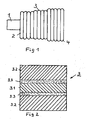
- FIG 1 is a side view of a thermally insulated conduit is shown according to the teachings of the invention, wherein the individual structural elements of the conduit are discontinued.
- the inner tube is called, which is the medium, usually this heating water from a district heating center, transported to the consumer.
- the inner tube 1 consists of a cross-linked polyethylene (PE-X), but may also consist of another plastic or be formed of metal, in particular as a corrugated tube.
- PE-X polyethylene
- two inner tubes 1 may be provided which are parallel and spaced from each other. Flow and return are then in a conduit.
- the inner tube 1 is surrounded by a thermal barrier coating 2, which consists of polyurethane foam which has been foamed with cyclopentane.
- the thermal barrier coating may consist of polyisocyanurate foam.
- a plastic film 3 which essentially serves as a mold for the developing foam.
- the plastic film prevents the cyclopentane from diffusing out, so that the polyurethane foam retains its shape and above all its heat-insulating properties for an extremely long period of time.
- plastic jacket 4 Over the plastic film is an extruded plastic jacket 4, which preferably consists of polyethylene.
- thermal barrier coating 2 In the thermal barrier coating 2, not shown electrical conductors may be provided, which in connection with a monitoring device in the thermal barrier coating 2 penetrate moisture and should locate.
- an electrical or optical cable can be provided in the thermal barrier coating, which can be used for data transmission.
- the heat-insulated conduit has an annular corrugation of the outer jacket 4. Due to the process, the surfaces of the thermal barrier coating 2 and the plastic film 3 are corrugated annular. This is due to the fact that the conduit is preferably produced by the process described in EP 0 897 788 B1.
- Figure 2 shows a section through a plastic film 3, as it is preferably used.
- the plastic film 3 has a core layer 3.1 and two edge layers 3.2.
- the core layer 3.1 is connected to the peripheral layers 3.2 by adhesion promoter layers 3.3.
- the core layer 3.1 consists of a material which is impermeable to cyclopentane, preferably of ethylene (vinyl alcohol copolymer (EVOH), polyvinyl alcohol (PVAL) or polyethylene terephthalate.)
- the peripheral layers 3.2 have the task of protecting the core layer 3.1 in the production of the conduit and of a good Bonding of the plastic film 3 with the thermal barrier coating 2 and the plastic outer tube 4.
- Polyethylene or polyamide is preferred as the material for the peripheral layers 3.2.
- the plastic film is produced in the laminating process, wherein 3.2 primer layers 3.3 are provided between the core layer 3.1 and the peripheral layers. Suitable materials for the primer layers are modified polyolefins which Contain carboxyl groups.
- the adhesion promoter layers 3.3 preferably contain an ethylene / vinyl acetate copolymer (EVA).
- An advantageously applicable plastic film has the following dimensions: Core situation 3.1 14 ⁇ m Bonding layer 5 ⁇ m Outlying locations 3.2 23 ⁇ m.
- the film has the advantage that it is conditionally permeable to water vapor. This results in the advantage that in inner tubes made of plastic z.
- B. Polyethylene the diffused through the wall of the inner tubes water vapor is discharged through the outer tube into the enclosure.
Landscapes
- Engineering & Computer Science (AREA)
- General Engineering & Computer Science (AREA)
- Mechanical Engineering (AREA)
- Food Science & Technology (AREA)
- Health & Medical Sciences (AREA)
- Nutrition Science (AREA)
- Polymers & Plastics (AREA)
- Life Sciences & Earth Sciences (AREA)
- Chemical & Material Sciences (AREA)
- Thermal Insulation (AREA)
- Laminated Bodies (AREA)
- Insulated Conductors (AREA)
- Buildings Adapted To Withstand Abnormal External Influences (AREA)
- Preparing Plates And Mask In Photomechanical Process (AREA)
- Resistance Heating (AREA)
- Protection Of Pipes Against Damage, Friction, And Corrosion (AREA)
Description
- Die Erfindung betrifft ein wärmeisoliertes Leitungsrohr nach dem Oberbegriff des Anspruchs 1.
- Aus der EP-0 634 602 B1 ist ein wärmeisoliertes Leitungsrohr bekannt, welches aus einem Innenrohr aus Kunststoff, einem im Abstand dazu konzentrisch angeordneten Außenrohr und einer den Ringraum zwischen Innen- und Außenrohr ausfüllenden Isolierschicht aus aufgeschäumtem Kunststoff auf der Basis von Polyurethan besteht. Die Isolierschicht ist von einer Folie umgeben, welche sowohl mit der Isolierschicht als auch mit dem Außenrohr verklebt ist. Alternativ zu dieser Lösung ist ein Metallband vorzugsweise ein Aluminiumband vorgesehen, welches unter anderem die Aufgabe hat, als Permeationssperre für das Treibgas zu wirken, um ein Ausdiffundieren des Treibgases weitestgehend zu unterbinden.
- Aus der EP-0 897 788 B1 ist ein Verfahren zur Herstellung eines wärmeisolierten Leitungsrohres bekannt, bei welchem ein oder mehrere Innenrohre von einer zu einem Schlauch geformten Kunststofffolie umhüllt werden, in den Raum zwischen dem Innenrohr und der Kunststofffolie ein aufschäumbarer Kunststoff eingebracht wird und anschließend ein Außenmantel aus thermoplastischem Kunststoff aufgebracht wird. Der aus der Kunststofffolie geformte Schlauch wird in einer Vorrichtung mit einer Vielzahl von paarweise angeordneten Formhälften geführt. Die Innenflächen der Formhälften weisen ein wellenförmiges Profil auf, in welches der Schlauch durch den sich ausbreitenden Schaum hineingeformt wird. Auf das wellenförmige Profil des Schlauches wird der Außenmantel aufgebracht, welcher somit ein wellenförmiges Außenprofil aufweist. Die Kunststofffolie besteht aus einem thermoformbaren Kunststoff z. B. aus Polyethylen.
- Der Nachteil bei den beschriebenen Leitungsrohren ist darin zu sehen, daß bei der Verwendung einer Polyethylenfolie eine Permeationssperre gegen die verwendeten Treibgase Kohldioxid, Pentan, Cyclopentan etc. nicht erreicht wird.
- Aus der EP 1 288 558 A1 ist ein wärmeisoliertes Leitungsrohr bekannt, welches aus einem Innenrohr, einer das Innenrohr umgebenden Wärmedämmschicht aus einem aufgeschäumten Kunststoff sowie einem Außenmantel aus Kunststoff besteht. Direkt auf der Wärmedämmschicht befindet sich eine bandförmige Lage aus Streckmetall. Auf die Streckmetallage ist eine thermoformbare Kunststofffolie aufgelegt, auf welche ein Strang schraubenlinienförmig aufgewickelt ist. Beim Aufschäumen drückt der sich entwickelnde Schaum durch die Öffnungen im Streckmetall und formt die Kunststofffolie in Form einer schraubenlinienförmigen Wellung nach außen. Bei der nachfolgenden Extrusion des Außenmantels legt sich dieser in die Wellung ein, so daß der Mantel ebenfalls eine schraubenlinienförmige Wellung erfährt. Die Kunststofffolie kann Barriereeigenschaften haben und weist zu diesem Zweck eine Metallbeschichtung auf.
- Die EP 0 960 723 A2 offenbart ein wärmeisoliertes Leitungsrohr mit einem Innenrohr aus Metall oder Kunststoff, einer Wärmedämmschicht auf der Basis von Polyurethan- oder Polyisocyanuratschaum sowie einem Kunststoffaußenrohr. Zwischen der Wärmedämmschicht und dem Außenrohr ist eine als Barriere für das Treibmittel für den Schaum dienende Verbundfolie vorgesehen, welche aus einer beidseitig mit Kunststoff beschichteten Metallfolie besteht. Die dem Außenrohr zugekehrte Kunststoffschicht besteht aus schmelzbarem Kunststoff, der durch die beim Aufschäumen des Polyurethans entstehende Wärme erweicht und mit der inneren Oberfläche des Außenrohres verklebt.
- Aus der DE 32 07 742 A1 ist ein wasserführendes Kunststoffrohr bekannt, welches mit einer Umfangshüllschicht versehen ist. Die Umfangshüllschicht besteht aus einer Gasdiffusionssperrschicht aus Polyamid, Polyvinylchlorid, Polyvinylalkohol oder einem Laminat solcher Kunststoffe mit außen liegenden Polyethylenschutzschichten.
- Die Verwendung einer Metallfolie zieht den Nachteil nach sich, daß eine Thermoformbarkeit nicht möglich ist, so daß ein Kunststoffaußenrohr mit einer gewellten Oberfläche nicht herstellbar ist.
- Der vorliegenden Erfindung liegt die Aufgabe zugrunde, ein wärmeisoliertes Leitungsrohr der eingangs erwähnten Art dahingehend zu verbessern, daß ein Ausdiffundieren des Treibgases durch den Kunststoffaußenmantel nahezu vollständig vermieden ist. Dabei soll die Folie thermoformbar sein, so daß das Leitungsrohr nach dem in der EP-0 897 788 beschriebenen Verfahren herstellbar ist.
- Diese Aufgabe wird durch das im Kennzeichen des Anspruchs 1 Erfaßte gelöst.
- Weitere vorteilhafte Ausführungen der Erfindung sind in den Unteransprüchen erfaßt.
- Der wesentliche Vorteil der Erfindung ist darin zu sehen, daß ein Ausdiffundieren der Treibgase weitestgehend unterbunden wird, so daß die Wärmedämmeigenschaften des Rohres über einen sehr langen Zeitraum von über 30 Jahren nahezu unverändert bleiben.
- Der neuartige Aufbau des Mantels gestattet es, daß das Leitungsrohr äußerst flexibel ist und über enge Radien von ca. 0,5 m gebogen werden kann, was sich vorteilhaft bei der Verlegung des Leitungsrohres auswirkt. Dadurch, daß die Kunststofffolie sowohl mit der Wärmedämmschicht als auch mit dem Kunststoffaußenmantel fest verklebt ist, ist eine Längswasserdichtigkeit erreicht und ein Einreißen der Kunststofffolie beim Biegen um enge Radien vermieden.
- Ein weiterer wesentlicher Vorteil besteht darin, daß größere Änderungen an dem in der EP 0 897 788 beschriebenen Verfahren nicht erforderlich sind.
- Die Erfindung beschränkt sich selbstredend nicht auf ein Leitungsrohr gemäß EP 0 634 602 oder EP 0 897 788 sondern ist auch anwendbar auf Leitungsrohre, wie sie aus der EP 0 892 207 bekannt sind.
- In den Figuren 1 und 2 ist ein Ausführungsbeispiel der Erfindung schematisch dargestellt.
- In der Figur 1 ist eine seitliche Ansicht eines wärmeisolierten Leitungsrohres nach der Lehre der Erfindung dargestellt, wobei die einzelnen Aufbauelemente des Leitungsrohres abgesetzt sind.
- Mit 1 ist das Innenrohr bezeichnet, welches das Medium, in der Regel ist dies Heizwasser aus einer Fernwärmezentrale, zum Verbraucher transportiert. Das Innenrohr 1 besteht aus einem vernetzten Polyethylen (PE-X), kann aber auch aus einem anderen Kunststoff bestehen oder aus Metall, insbesondere als Wellrohr ausgebildet sein. In dem Leitungsrohr können auch zwei Innenrohre 1 vorgesehen sein, welche parallel und im Abstand zueinander verlaufen. Vor- und Rücklauf liegen dann in einem Leitungsrohr.
- Das Innenrohr 1 ist von einer Wärmedämmschicht 2 umgeben, welche aus Polyurethanschaum besteht, der mit Cyclopentan aufgeschäumt wurde. Alternativ kann die Wärmedämmschicht aus Polyisocyanuratschaum bestehen.
- Über der Wärmedämmschicht 2 liegt eine Kunststofffolie 3, welche im Wesentlichen als Form für den sich entwickelndem Schaum dient. Darüberhinaus verhindert die Kunststofffolie ein Hinausdiffundieren des Cyclopentans, so daß der Polyurethanschaum über einen extrem langen Zeitraum seine Form und vor allem seine Wärmedämmeigenschaften beibehält.
- Über der Kunststofffolie liegt ein extrudierter Kunststoffmantel 4, der vorzugsweise aus Polyethylen besteht.
- In der Wärmedämmschicht 2 können noch nicht dargestellte elektrische Leiter vorgesehen sein, welche im Zusammenhang mit einer Überwachungseinrichtung in die Wärmedämmschicht 2 eingedrungene Feuchtigkeit melden und orten sollen.
- Darüberhinaus kann in der Wärmedämmschicht ein elektrisches oder optisches Kabel vorgesehen werden, welches zur Datenübertragung verwendet werden kann.
- Das wärmeisolierte Leitungsrohr weist eine ringförmige Wellung des Außenmantels 4 auf. Verfahrensbedingt sind auch die Oberflächen der Wärmedämmschicht 2 sowie der Kunststofffolie 3 ringförmig gewellt. Dies rührt daher, daß das Leitungsrohr bevorzugt nach dem in der EP 0 897 788 B1 beschriebenen Verfahren hergestellt wird.
- Die Figur 2 zeigt einen Schnitt durch eine Kunststofffolie 3, wie sie bevorzugt verwendet wird.
- Die Kunststofffolie 3 weist eine Kernlage 3.1 sowie zwei Randlagen 3.2 auf. Die Kernlage 3.1 ist mit den Randlagen 3.2 durch Haftvermittlerlagen 3.3 verbunden.
- Die Kernlage 3.1 besteht aus einem für Cyclopentan undurchlässigen Material, vorzugsweise aus Ethylen(Vinylalkohol-Copolymer (EVOH), Polyvinylalkohol (PVAL) oder Polyethylenterephthalat. Die Randlagen 3.2 haben die Aufgabe, die Kernlage 3.1 bei der Herstellung des Leitungsrohres zu schützen sowie für eine gute Verklebung der Kunststofffolie 3 mit der Wärmedämmschicht 2 sowie dem Kunststoffaußenrohr 4 zu sorgen. Als Material für die Randlagen 3.2 wird Polyethylen oder Polyamid bevorzugt.
- Die Kunststofffolie wird im Kaschierverfahren hergestellt, wobei zwischen der Kernlage 3.1 und den Randlagen 3.2 Haftvermittlerschichten 3.3 vorgesehen werden. Als Werkstoff für die Haftvermittlerschichten eignen sich modifizierte Polyolefine, welche Carboxylgruppen enthalten. Bevorzugt enthalten die Haftvermittlerschichten 3.3 ein Ethylen/Vinylacetat-Copolymerisat (EVA).
- Eine mit Vorteil anwendbare Kunststofffolie hat folgenden Abmessungen:
Kernlage 3.1 14 µm Haftvermittlerschicht 5 µm Randlagen 3.2 23 µm. - Neben der guten Undurchlässigkeit für Cyclopentan weist die Folie den Vorteil auf, daß sie für Wasserdampf bedingt durchlässig ist. Daraus resultiert der Vorteil, daß bei Innenrohren aus Kunststoff z. B. Polyethylen der durch die Wandung der Innenrohre hindurchdiffundierte Wasserdampf durch das Außenrohr in die Umhüllung abgeleitet wird.
Claims (11)
- Wärmeisoliertes Leitungsrohr mit zumindest einem Innenrohr (1), einer direkt auf dem Innenrohr aufliegenden Wärmedämmschicht (2) auf der Basis von aufgeschäumten Polyurethan oder Polyisocyanurat sowie einem Außenmantel (4) aus thermoplastischem Kunststoff, der eine gewellte Oberfläche aufweist, bei welchem Leitungsrohr zwischen der Wärmedämmschicht (2) und dem Außenmantel (4) eine sowohl mit dem Außenmantel (4) als auch mit der Wärmedämmschicht (2) in Berührung stehende thermoformbare Kunststofffolie (3) vorgesehen ist, dadurch gekennzeichnet, daß die Kunststofffolie (3) aus mehreren nichtmetallischen Schichten (3.1,3.2,3.3) besteht, daß zumindest eine der Schichten (3.1) für das in den Zellen des aufgeschäumten Polyurethans oder Polyisocyanurats befindliche Treibgas undurchlässig ist, und daß sowohl die dem Außenmantel (4) zugekehrte Schicht (3.2) mit diesem als auch die der Wärmedämmschicht (2) zugekehrte Schicht (3.2) mit dieser verklebt ist.
- Wärmeisoliertes Leitungsrohr nach Anspruch 1, dadurch gekennzeichnet, daß die für das Treibgas undurchlässige Schicht (3.1) aus Ethylen/Vinylalkohol-Copolymer (EVOH) besteht.
- Wärmeisoliertes Leitungsrohr nach Anspruch 1, dadurch gekennzeichnet, daß die für das Treibgas undurchlässige Schicht (3.1) aus Polyvinylalkohol (PVAL) besteht.
- Wärmeisoliertes Leitungsrohr nach Anspruch 1, dadurch gekennzeichnet, daß die für das Treibgas undurchlässige Schicht (3.1) aus Polyethylenterephthalat besteht.
- Wärmeisoliertes Leitungsrohr nach einem der Ansprüche 1 bis 4, dadurch gekennzeichnet, daß die dem Außenmantel (4) und der Wärmedämmschicht (2) zugekehrte Schichten (3.2) aus einem thermoplastischen Kunststoff, vorzugsweise aus Polyethylen (PE), Polyamid (PA) oder Ethylenvinylacetat (EVA) bestehen.
- Wärmeisoliertes Leitungsrohr nach einem der Ansprüche 1 bis 5, dadurch gekennzeichnet, daß die Kunststofffolie (3) eine Verbundfolie ist und die einzelnen Schichten (3.1,3.2) durch jeweils eine Haftvermittlerschicht (3.3) verbunden sind.
- Wärmeisoliertes Leitungsrohr nach Anspruch 6, dadurch gekennzeichnet, daß die Haftvermittlerschicht (3.3) ein modifiziertes Polyolefin mit Carboxylgruppen enthält.
- Wärmeisoliertes Leitungsrohr nach Anspruch 6, dadurch gekennzeichnet, daß die Haftvermittlerschicht (3.3) ein Ethylen/Vinylacetat-Copolymerisat enthält.
- Wärmeisoliertes Leitungsrohr nach einem der Ansprüche 1 bis 8, dadurch gekennzeichnet, daß die Wanddicke der Folie (3) 60 bis 70 µm beträgt.
- Wärmeisoliertes Leitungsrohr nach einem der Ansprüche 1 bis 9, dadurch gekennzeichnet, daß die Wanddicke der für das Treibgas undurchlässigen Schicht (3.1) 10 bis 20 µm vorzugsweise 12 bis 16 µm beträgt.
- Wärmeisoliertes Leitungsrohr nach einem der Ansprüche 1 bis 10, dadurch gekennzeichnet, daß die Wanddicke der außengelegenen Schichten (3.2) aus thermoplastischem Material 15 bis 25 µm beträgt.
Applications Claiming Priority (2)
| Application Number | Priority Date | Filing Date | Title |
|---|---|---|---|
| DE20303698U | 2003-03-08 | ||
| DE20303698U DE20303698U1 (de) | 2003-03-08 | 2003-03-08 | Wärmeisoliertes Leitungsrohr |
Publications (2)
| Publication Number | Publication Date |
|---|---|
| EP1471299A1 EP1471299A1 (de) | 2004-10-27 |
| EP1471299B1 true EP1471299B1 (de) | 2007-01-31 |
Family
ID=7980636
Family Applications (1)
| Application Number | Title | Priority Date | Filing Date |
|---|---|---|---|
| EP04003996A Expired - Lifetime EP1471299B1 (de) | 2003-03-08 | 2004-02-23 | Wärmeisoliertes Leitungsrohr |
Country Status (9)
| Country | Link |
|---|---|
| EP (1) | EP1471299B1 (de) |
| JP (1) | JP4643917B2 (de) |
| KR (1) | KR101105517B1 (de) |
| CN (1) | CN1316196C (de) |
| AT (1) | ATE353127T1 (de) |
| DE (2) | DE20303698U1 (de) |
| DK (1) | DK1471299T3 (de) |
| PL (1) | PL204565B1 (de) |
| RU (1) | RU2289751C2 (de) |
Cited By (1)
| Publication number | Priority date | Publication date | Assignee | Title |
|---|---|---|---|---|
| US11879586B2 (en) | 2016-07-20 | 2024-01-23 | Brugg Rohr Ag Holding | Thermally insulated medium pipes having HFO-containing cell gas |
Families Citing this family (15)
| Publication number | Priority date | Publication date | Assignee | Title |
|---|---|---|---|---|
| EP1355103B1 (de) | 2002-04-05 | 2018-10-10 | Logstor A/S | Vorisoliertes Rohr |
| DE202006009337U1 (de) * | 2006-06-14 | 2006-08-17 | Brugg Rohr Ag, Holding | Wärmegedämmtes Leitungsrohr |
| DE102007015660A1 (de) | 2007-03-31 | 2008-10-02 | Brugg Rohr Ag, Holding | Flexibles wärmeisoliertes Leitungsrohr |
| RU2343340C1 (ru) * | 2007-06-04 | 2009-01-10 | Общество с ограниченной ответственностью "Группа компаний Сибирский ориентир" | Способ осуществления сборно-разборного теплоизоляционного покрытия трубопровода |
| JP4580412B2 (ja) * | 2007-07-20 | 2010-11-10 | 明星工業株式会社 | 断熱材及び断熱対象物に対して断熱材を被覆する断熱構造 |
| LT2586602T (lt) | 2010-06-28 | 2018-12-27 | Obschestvo S Ogranichennoy Otvetstvennostiyu "Smit-Yartsevo" | Termoizoliacinio lankstaus vamzdžio gamybos būdas |
| LT2620268T (lt) | 2010-09-20 | 2017-01-25 | Obschestvo S Ogranichennoy Otvetstvennostiyu "Smit-Yartsevo" | Lankstaus vamzdžio su termine izoliacija gamybos linija |
| US9297491B2 (en) * | 2012-02-08 | 2016-03-29 | Federal-Mogul Powertrain, Inc. | Thermally resistant convoluted sleeve and method of construction thereof |
| AU2013292168A1 (en) * | 2012-07-17 | 2015-02-05 | Basf Se | Method for continuous production of foams in tubes |
| KR101800047B1 (ko) | 2013-05-03 | 2017-12-20 | (주)엘지하우시스 | 진공단열재용 외피재 및 이를 포함하는 고성능 진공단열재 |
| EP2816274A1 (de) | 2013-06-17 | 2014-12-24 | Radpol S.A. | Vorisolierter Rohrmantel und Verfahren zur Herstellung eines vorisolierten Rohrmantels |
| CN104295845A (zh) * | 2014-09-26 | 2015-01-21 | 哈尔滨朗格斯特节能科技有限公司 | 智能预制直埋保温管交联聚乙烯工作管件弯头及制作方法 |
| DE102015109313B4 (de) * | 2015-06-11 | 2018-02-01 | Brugg Rohr Ag, Holding | Doppelwandiges Leitungsrohr mit einer Wärmedämmschicht sowie ein hierfür bestimmtes Kunststoffaußenrohr |
| RU182970U1 (ru) * | 2018-04-02 | 2018-09-06 | Павел Борисович Куприн | Устройство изоляции трубопровода |
| EP3871873A1 (de) * | 2020-02-26 | 2021-09-01 | Brugg Rohr AG Holding | Thermisch gedämmtes rohr |
Family Cites Families (14)
| Publication number | Priority date | Publication date | Assignee | Title |
|---|---|---|---|---|
| FR1308239A (fr) | 1961-10-14 | 1962-11-03 | Hackethal Draht & Kabelwerk Ag | Tubes de canalisations isolés notamment tubes calorifugés et insonorisés |
| DE1928977A1 (de) | 1969-06-07 | 1970-12-10 | Kabel Metallwerke Ghh | Waermeisoliertes Leitungsrohr und Verfahren zu seiner Herstellung |
| DE3207742C2 (de) * | 1982-03-04 | 1986-07-24 | REHAU AG + Co, 8673 Rehau | Verwendung einer Mehrschichten-Folie aus Kunststoff als Umfangshüllschicht für warmwasserführende Kunststoff-Rohre |
| DE4018753A1 (de) | 1990-06-12 | 1991-12-19 | Platzer Schwedenbau Gmbh | Mehrschichtrohr |
| JPH05138821A (ja) * | 1991-11-22 | 1993-06-08 | Bridgestone Corp | ガスバリア性ゴム積層物 |
| DE9310530U1 (de) | 1993-07-15 | 1993-09-09 | Ke Rohrsysteme und Umwelttechnik GmbH, 30179 Hannover | Wärmeisoliertes Leitungsrohr |
| DE69718765T2 (de) * | 1996-02-20 | 2003-10-16 | Kabushiki Kaisha Meiji Gomu Kasei, Tokio/Tokyo | Kühlmittelförderschlauch |
| DE19629678A1 (de) * | 1996-07-23 | 1998-01-29 | Brugg Rohrsysteme Gmbh | Verfahren zur Herstellung eines wärmeisolierten Leitungsrohres |
| DE29712560U1 (de) | 1997-07-16 | 1997-09-18 | BRUGG Rohrsysteme GmbH, 31515 Wunstorf | Wärmeisoliertes Leitungsrohr |
| RU2115058C1 (ru) * | 1997-12-19 | 1998-07-10 | Анатолий Степанович Федоров | Теплопровод |
| DE19823585A1 (de) * | 1998-05-27 | 1999-12-02 | Basf Ag | Verbundelement enthaltend Polyisocyanat-Polyadditionsprodukte |
| DE60030514T2 (de) * | 1999-08-12 | 2007-07-05 | Sumitomo Chemical Co., Ltd. | Mehrschichtige geschäumte Polyolefin-Folie, Verfahren und Vorrichtung zur deren Herstellung |
| JP2002240173A (ja) * | 2001-02-19 | 2002-08-28 | Nkk Corp | 合成樹脂管 |
| DE10142719A1 (de) * | 2001-08-31 | 2003-04-03 | Brugg Rohrsysteme Gmbh | Wärmeisoliertes Leitungsrohr |
-
2003
- 2003-03-08 DE DE20303698U patent/DE20303698U1/de not_active Expired - Lifetime
-
2004
- 2004-02-23 EP EP04003996A patent/EP1471299B1/de not_active Expired - Lifetime
- 2004-02-23 DE DE502004002818T patent/DE502004002818D1/de not_active Expired - Lifetime
- 2004-02-23 AT AT04003996T patent/ATE353127T1/de active
- 2004-02-23 DK DK04003996T patent/DK1471299T3/da active
- 2004-03-05 JP JP2004062618A patent/JP4643917B2/ja not_active Expired - Fee Related
- 2004-03-05 RU RU2004106714/06A patent/RU2289751C2/ru not_active IP Right Cessation
- 2004-03-05 CN CNB2004100080197A patent/CN1316196C/zh not_active Expired - Fee Related
- 2004-03-08 PL PL365979A patent/PL204565B1/pl unknown
- 2004-03-08 KR KR1020040015412A patent/KR101105517B1/ko not_active Expired - Fee Related
Cited By (1)
| Publication number | Priority date | Publication date | Assignee | Title |
|---|---|---|---|---|
| US11879586B2 (en) | 2016-07-20 | 2024-01-23 | Brugg Rohr Ag Holding | Thermally insulated medium pipes having HFO-containing cell gas |
Also Published As
| Publication number | Publication date |
|---|---|
| CN1550704A (zh) | 2004-12-01 |
| ATE353127T1 (de) | 2007-02-15 |
| RU2004106714A (ru) | 2005-08-10 |
| PL204565B1 (pl) | 2010-01-29 |
| JP4643917B2 (ja) | 2011-03-02 |
| DE20303698U1 (de) | 2003-05-15 |
| KR20040079861A (ko) | 2004-09-16 |
| DK1471299T3 (da) | 2007-06-04 |
| PL365979A1 (en) | 2004-09-20 |
| JP2004270943A (ja) | 2004-09-30 |
| RU2289751C2 (ru) | 2006-12-20 |
| DE502004002818D1 (de) | 2007-03-22 |
| KR101105517B1 (ko) | 2012-01-19 |
| EP1471299A1 (de) | 2004-10-27 |
| CN1316196C (zh) | 2007-05-16 |
Similar Documents
| Publication | Publication Date | Title |
|---|---|---|
| EP1471299B1 (de) | Wärmeisoliertes Leitungsrohr | |
| EP0897788B1 (de) | Verfahren zur Herstellung eines wärmeisolierten Leitungsrohres | |
| CA1124632A (en) | Insulating pipe sheath | |
| KR101333475B1 (ko) | 열 절연 파이프 | |
| EP0054751B1 (de) | Heizungsrohr aus Kunststoff für Fussbodenheizungen mit sauerstoffdichter Ummantelung | |
| EP1125082B1 (de) | Schlauch zur auskleidung von rohrleitungen und verfahren zu dessen herstellung | |
| US4706711A (en) | Elastic technical hose with a foam insert | |
| EP3112124B1 (de) | Verfahren zur beschichtung einer rohrleitung | |
| EP2137451B1 (de) | Kunststoffrohr | |
| DE1625936C3 (de) | Durch Biegen verformbares Leitungsrohr aus Metall für Heizungsanlagen und Wasserinstallationen, insbesondere Warmwasserleitungen | |
| DE3307120A1 (de) | Fernwaermeleitungsrohr | |
| EP3256770B1 (de) | Leitungsrohr mit thermischer dämmung | |
| EP4269855B1 (de) | Thermisch gedämmtes leitungsrohr | |
| EP3104058B1 (de) | Doppelwandiges leitungsrohr mit einer wärmedämmschicht sowie ein hierfür bestimmtes kunststoffaussenrohr | |
| DE2542431C3 (de) | Verfahren zum Herstellen eines isolierten Rohrs | |
| DE3446340C2 (de) | ||
| EP1208962B1 (de) | Verfahren zur kontinuierlichen Herstellung eines wenigstens drei Lagen aufweisenden Isolierschlauchs | |
| EP1909018A2 (de) | Rohrverbindungsformteil mit thermischer Isolierung und Verfahren zur Herstellung des Rohrverbindungsformteiles | |
| EP1566587B1 (de) | Diffusionsdichtes Kunststoffrohr | |
| EP4575290A1 (de) | Mehrschichtiger wellrohraussenmantel sowie diesen umfassende rohranordnung | |
| DE8320278U1 (de) | Rohrstrang fuer die wasser- und heizungsinstallation | |
| DE202023107575U1 (de) | Wärmegedämmtes Wellrohraußenmantel sowie dieses umfassendes Wärmeverteilsystem | |
| DE102023136192A1 (de) | Verfahren zur kontinuierlichen Herstellung eines wärmegedämmten Wellrohrs sowie dadurch erhaltenes wärmegedämmtes Wellrohr | |
| DE9308602U1 (de) | Flexibles wärmeisoliertes Leitungsrohr | |
| DE202004008813U1 (de) | Mehrwandisolationsrohr |
Legal Events
| Date | Code | Title | Description |
|---|---|---|---|
| PUAI | Public reference made under article 153(3) epc to a published international application that has entered the european phase |
Free format text: ORIGINAL CODE: 0009012 |
|
| AK | Designated contracting states |
Kind code of ref document: A1 Designated state(s): AT BE BG CH CY CZ DE DK EE ES FI FR GB GR HU IE IT LI LU MC NL PT RO SE SI SK TR |
|
| AX | Request for extension of the european patent |
Extension state: AL LT LV MK |
|
| 17P | Request for examination filed |
Effective date: 20041008 |
|
| AKX | Designation fees paid |
Designated state(s): AT BE BG CH CY CZ DE DK EE ES FI FR GB GR HU IE IT LI LU MC NL PT RO SE SI SK TR |
|
| GRAP | Despatch of communication of intention to grant a patent |
Free format text: ORIGINAL CODE: EPIDOSNIGR1 |
|
| GRAS | Grant fee paid |
Free format text: ORIGINAL CODE: EPIDOSNIGR3 |
|
| GRAA | (expected) grant |
Free format text: ORIGINAL CODE: 0009210 |
|
| AK | Designated contracting states |
Kind code of ref document: B1 Designated state(s): AT BE BG CH CY CZ DE DK EE ES FI FR GB GR HU IE IT LI LU MC NL PT RO SE SI SK TR |
|
| PG25 | Lapsed in a contracting state [announced via postgrant information from national office to epo] |
Ref country code: SI Free format text: LAPSE BECAUSE OF FAILURE TO SUBMIT A TRANSLATION OF THE DESCRIPTION OR TO PAY THE FEE WITHIN THE PRESCRIBED TIME-LIMIT Effective date: 20070131 Ref country code: IE Free format text: LAPSE BECAUSE OF FAILURE TO SUBMIT A TRANSLATION OF THE DESCRIPTION OR TO PAY THE FEE WITHIN THE PRESCRIBED TIME-LIMIT Effective date: 20070131 |
|
| REG | Reference to a national code |
Ref country code: GB Ref legal event code: FG4D Free format text: NOT ENGLISH |
|
| PG25 | Lapsed in a contracting state [announced via postgrant information from national office to epo] |
Ref country code: MC Free format text: LAPSE BECAUSE OF NON-PAYMENT OF DUE FEES Effective date: 20070228 |
|
| REG | Reference to a national code |
Ref country code: CH Ref legal event code: NV Representative=s name: PA ALDO ROEMPLER Ref country code: CH Ref legal event code: EP |
|
| REG | Reference to a national code |
Ref country code: IE Ref legal event code: FG4D Free format text: LANGUAGE OF EP DOCUMENT: GERMAN |
|
| REF | Corresponds to: |
Ref document number: 502004002818 Country of ref document: DE Date of ref document: 20070322 Kind code of ref document: P |
|
| PG25 | Lapsed in a contracting state [announced via postgrant information from national office to epo] |
Ref country code: BG Free format text: LAPSE BECAUSE OF FAILURE TO SUBMIT A TRANSLATION OF THE DESCRIPTION OR TO PAY THE FEE WITHIN THE PRESCRIBED TIME-LIMIT Effective date: 20070501 |
|
| PG25 | Lapsed in a contracting state [announced via postgrant information from national office to epo] |
Ref country code: ES Free format text: LAPSE BECAUSE OF FAILURE TO SUBMIT A TRANSLATION OF THE DESCRIPTION OR TO PAY THE FEE WITHIN THE PRESCRIBED TIME-LIMIT Effective date: 20070512 |
|
| REG | Reference to a national code |
Ref country code: SE Ref legal event code: TRGR |
|
| PG25 | Lapsed in a contracting state [announced via postgrant information from national office to epo] |
Ref country code: PT Free format text: LAPSE BECAUSE OF FAILURE TO SUBMIT A TRANSLATION OF THE DESCRIPTION OR TO PAY THE FEE WITHIN THE PRESCRIBED TIME-LIMIT Effective date: 20070702 |
|
| ET | Fr: translation filed | ||
| GBV | Gb: ep patent (uk) treated as always having been void in accordance with gb section 77(7)/1977 [no translation filed] |
Effective date: 20070131 |
|
| REG | Reference to a national code |
Ref country code: IE Ref legal event code: FD4D |
|
| PG25 | Lapsed in a contracting state [announced via postgrant information from national office to epo] |
Ref country code: SK Free format text: LAPSE BECAUSE OF FAILURE TO SUBMIT A TRANSLATION OF THE DESCRIPTION OR TO PAY THE FEE WITHIN THE PRESCRIBED TIME-LIMIT Effective date: 20070131 Ref country code: GB Free format text: LAPSE BECAUSE OF FAILURE TO SUBMIT A TRANSLATION OF THE DESCRIPTION OR TO PAY THE FEE WITHIN THE PRESCRIBED TIME-LIMIT Effective date: 20070131 |
|
| PLBE | No opposition filed within time limit |
Free format text: ORIGINAL CODE: 0009261 |
|
| STAA | Information on the status of an ep patent application or granted ep patent |
Free format text: STATUS: NO OPPOSITION FILED WITHIN TIME LIMIT |
|
| PG25 | Lapsed in a contracting state [announced via postgrant information from national office to epo] |
Ref country code: RO Free format text: LAPSE BECAUSE OF FAILURE TO SUBMIT A TRANSLATION OF THE DESCRIPTION OR TO PAY THE FEE WITHIN THE PRESCRIBED TIME-LIMIT Effective date: 20070131 Ref country code: CZ Free format text: LAPSE BECAUSE OF FAILURE TO SUBMIT A TRANSLATION OF THE DESCRIPTION OR TO PAY THE FEE WITHIN THE PRESCRIBED TIME-LIMIT Effective date: 20070131 |
|
| 26N | No opposition filed |
Effective date: 20071101 |
|
| PG25 | Lapsed in a contracting state [announced via postgrant information from national office to epo] |
Ref country code: GR Free format text: LAPSE BECAUSE OF FAILURE TO SUBMIT A TRANSLATION OF THE DESCRIPTION OR TO PAY THE FEE WITHIN THE PRESCRIBED TIME-LIMIT Effective date: 20070501 |
|
| REG | Reference to a national code |
Ref country code: CH Ref legal event code: PCAR Free format text: ALDO ROEMPLER PATENTANWALT;BRENDENWEG 11 POSTFACH 154;9424 RHEINECK (CH) |
|
| PG25 | Lapsed in a contracting state [announced via postgrant information from national office to epo] |
Ref country code: EE Free format text: LAPSE BECAUSE OF FAILURE TO SUBMIT A TRANSLATION OF THE DESCRIPTION OR TO PAY THE FEE WITHIN THE PRESCRIBED TIME-LIMIT Effective date: 20070131 |
|
| PG25 | Lapsed in a contracting state [announced via postgrant information from national office to epo] |
Ref country code: CY Free format text: LAPSE BECAUSE OF FAILURE TO SUBMIT A TRANSLATION OF THE DESCRIPTION OR TO PAY THE FEE WITHIN THE PRESCRIBED TIME-LIMIT Effective date: 20070131 |
|
| PG25 | Lapsed in a contracting state [announced via postgrant information from national office to epo] |
Ref country code: LU Free format text: LAPSE BECAUSE OF NON-PAYMENT OF DUE FEES Effective date: 20070223 |
|
| PG25 | Lapsed in a contracting state [announced via postgrant information from national office to epo] |
Ref country code: HU Free format text: LAPSE BECAUSE OF FAILURE TO SUBMIT A TRANSLATION OF THE DESCRIPTION OR TO PAY THE FEE WITHIN THE PRESCRIBED TIME-LIMIT Effective date: 20070801 |
|
| PGFP | Annual fee paid to national office [announced via postgrant information from national office to epo] |
Ref country code: TR Payment date: 20110223 Year of fee payment: 8 |
|
| PG25 | Lapsed in a contracting state [announced via postgrant information from national office to epo] |
Ref country code: TR Free format text: LAPSE BECAUSE OF NON-PAYMENT OF DUE FEES Effective date: 20120223 |
|
| REG | Reference to a national code |
Ref country code: FR Ref legal event code: PLFP Year of fee payment: 13 |
|
| REG | Reference to a national code |
Ref country code: FR Ref legal event code: PLFP Year of fee payment: 14 |
|
| REG | Reference to a national code |
Ref country code: FR Ref legal event code: PLFP Year of fee payment: 15 |
|
| PGFP | Annual fee paid to national office [announced via postgrant information from national office to epo] |
Ref country code: NL Payment date: 20190224 Year of fee payment: 16 |
|
| PGFP | Annual fee paid to national office [announced via postgrant information from national office to epo] |
Ref country code: BE Payment date: 20190222 Year of fee payment: 16 |
|
| PGFP | Annual fee paid to national office [announced via postgrant information from national office to epo] |
Ref country code: SE Payment date: 20200219 Year of fee payment: 17 Ref country code: AT Payment date: 20200219 Year of fee payment: 17 Ref country code: FI Payment date: 20200220 Year of fee payment: 17 |
|
| PGFP | Annual fee paid to national office [announced via postgrant information from national office to epo] |
Ref country code: CH Payment date: 20200220 Year of fee payment: 17 |
|
| REG | Reference to a national code |
Ref country code: NL Ref legal event code: MM Effective date: 20200301 |
|
| REG | Reference to a national code |
Ref country code: BE Ref legal event code: MM Effective date: 20200229 |
|
| PG25 | Lapsed in a contracting state [announced via postgrant information from national office to epo] |
Ref country code: NL Free format text: LAPSE BECAUSE OF NON-PAYMENT OF DUE FEES Effective date: 20200301 |
|
| PG25 | Lapsed in a contracting state [announced via postgrant information from national office to epo] |
Ref country code: FR Free format text: LAPSE BECAUSE OF NON-PAYMENT OF DUE FEES Effective date: 20200229 |
|
| PG25 | Lapsed in a contracting state [announced via postgrant information from national office to epo] |
Ref country code: BE Free format text: LAPSE BECAUSE OF NON-PAYMENT OF DUE FEES Effective date: 20200229 |
|
| PGFP | Annual fee paid to national office [announced via postgrant information from national office to epo] |
Ref country code: DK Payment date: 20210219 Year of fee payment: 18 Ref country code: DE Payment date: 20210301 Year of fee payment: 18 |
|
| REG | Reference to a national code |
Ref country code: SE Ref legal event code: EUG |
|
| REG | Reference to a national code |
Ref country code: FI Ref legal event code: MAE |
|
| REG | Reference to a national code |
Ref country code: AT Ref legal event code: MM01 Ref document number: 353127 Country of ref document: AT Kind code of ref document: T Effective date: 20210223 |
|
| PG25 | Lapsed in a contracting state [announced via postgrant information from national office to epo] |
Ref country code: IT Free format text: LAPSE BECAUSE OF NON-PAYMENT OF DUE FEES Effective date: 20200223 Ref country code: CH Free format text: LAPSE BECAUSE OF NON-PAYMENT OF DUE FEES Effective date: 20210228 Ref country code: AT Free format text: LAPSE BECAUSE OF NON-PAYMENT OF DUE FEES Effective date: 20210223 Ref country code: LI Free format text: LAPSE BECAUSE OF NON-PAYMENT OF DUE FEES Effective date: 20210228 Ref country code: FI Free format text: LAPSE BECAUSE OF NON-PAYMENT OF DUE FEES Effective date: 20210223 |
|
| PG25 | Lapsed in a contracting state [announced via postgrant information from national office to epo] |
Ref country code: SE Free format text: LAPSE BECAUSE OF NON-PAYMENT OF DUE FEES Effective date: 20210224 |
|
| REG | Reference to a national code |
Ref country code: DE Ref legal event code: R119 Ref document number: 502004002818 Country of ref document: DE |
|
| REG | Reference to a national code |
Ref country code: DK Ref legal event code: EBP Effective date: 20220228 |
|
| PG25 | Lapsed in a contracting state [announced via postgrant information from national office to epo] |
Ref country code: DK Free format text: LAPSE BECAUSE OF NON-PAYMENT OF DUE FEES Effective date: 20220228 Ref country code: DE Free format text: LAPSE BECAUSE OF NON-PAYMENT OF DUE FEES Effective date: 20220901 |