EP1471302B1 - Anschlussvorrichtung für durch die Behälterwand eines Treibstoffbehälters durchgeführten elektrischen Anschlüsse, insbesondere für den Flüssiggasbehälter eines motorbetriebenen Fahrzeugs - Google Patents
Anschlussvorrichtung für durch die Behälterwand eines Treibstoffbehälters durchgeführten elektrischen Anschlüsse, insbesondere für den Flüssiggasbehälter eines motorbetriebenen Fahrzeugs Download PDFInfo
- Publication number
- EP1471302B1 EP1471302B1 EP04002647A EP04002647A EP1471302B1 EP 1471302 B1 EP1471302 B1 EP 1471302B1 EP 04002647 A EP04002647 A EP 04002647A EP 04002647 A EP04002647 A EP 04002647A EP 1471302 B1 EP1471302 B1 EP 1471302B1
- Authority
- EP
- European Patent Office
- Prior art keywords
- tank
- connector
- plate
- wall
- connector member
- Prior art date
- Legal status (The legal status is an assumption and is not a legal conclusion. Google has not performed a legal analysis and makes no representation as to the accuracy of the status listed.)
- Expired - Lifetime
Links
- 239000002828 fuel tank Substances 0.000 title claims abstract description 14
- 239000000446 fuel Substances 0.000 title description 2
- 239000004020 conductor Substances 0.000 claims abstract description 22
- 239000000463 material Substances 0.000 claims abstract description 11
- 229920001971 elastomer Polymers 0.000 claims abstract description 9
- 239000000806 elastomer Substances 0.000 claims abstract description 9
- 229920002994 synthetic fiber Polymers 0.000 claims abstract description 6
- 238000007789 sealing Methods 0.000 abstract description 6
- 239000011521 glass Substances 0.000 description 5
- 239000000243 solution Substances 0.000 description 5
- 238000009434 installation Methods 0.000 description 4
- 229910000831 Steel Inorganic materials 0.000 description 2
- 238000010276 construction Methods 0.000 description 2
- VNWKTOKETHGBQD-UHFFFAOYSA-N methane Chemical compound C VNWKTOKETHGBQD-UHFFFAOYSA-N 0.000 description 2
- 239000010959 steel Substances 0.000 description 2
- 238000005336 cracking Methods 0.000 description 1
- 230000004927 fusion Effects 0.000 description 1
- 238000002347 injection Methods 0.000 description 1
- 239000007924 injection Substances 0.000 description 1
- 238000009413 insulation Methods 0.000 description 1
- 239000007769 metal material Substances 0.000 description 1
- 239000004033 plastic Substances 0.000 description 1
- 230000035939 shock Effects 0.000 description 1
- 239000012815 thermoplastic material Substances 0.000 description 1
Images

Classifications
-
- H—ELECTRICITY
- H01—ELECTRIC ELEMENTS
- H01R—ELECTRICALLY-CONDUCTIVE CONNECTIONS; STRUCTURAL ASSOCIATIONS OF A PLURALITY OF MUTUALLY-INSULATED ELECTRICAL CONNECTING ELEMENTS; COUPLING DEVICES; CURRENT COLLECTORS
- H01R13/00—Details of coupling devices of the kinds covered by groups H01R12/70 or H01R24/00 - H01R33/00
- H01R13/46—Bases; Cases
- H01R13/52—Dustproof, splashproof, drip-proof, waterproof, or flameproof cases
- H01R13/5202—Sealing means between parts of housing or between housing part and a wall, e.g. sealing rings
-
- F—MECHANICAL ENGINEERING; LIGHTING; HEATING; WEAPONS; BLASTING
- F17—STORING OR DISTRIBUTING GASES OR LIQUIDS
- F17C—VESSELS FOR CONTAINING OR STORING COMPRESSED, LIQUEFIED OR SOLIDIFIED GASES; FIXED-CAPACITY GAS-HOLDERS; FILLING VESSELS WITH, OR DISCHARGING FROM VESSELS, COMPRESSED, LIQUEFIED, OR SOLIDIFIED GASES
- F17C13/00—Details of vessels or of the filling or discharging of vessels
- F17C13/04—Arrangement or mounting of valves
-
- H—ELECTRICITY
- H01—ELECTRIC ELEMENTS
- H01R—ELECTRICALLY-CONDUCTIVE CONNECTIONS; STRUCTURAL ASSOCIATIONS OF A PLURALITY OF MUTUALLY-INSULATED ELECTRICAL CONNECTING ELEMENTS; COUPLING DEVICES; CURRENT COLLECTORS
- H01R13/00—Details of coupling devices of the kinds covered by groups H01R12/70 or H01R24/00 - H01R33/00
- H01R13/46—Bases; Cases
- H01R13/52—Dustproof, splashproof, drip-proof, waterproof, or flameproof cases
- H01R13/521—Sealing between contact members and housing, e.g. sealing insert
-
- H—ELECTRICITY
- H01—ELECTRIC ELEMENTS
- H01R—ELECTRICALLY-CONDUCTIVE CONNECTIONS; STRUCTURAL ASSOCIATIONS OF A PLURALITY OF MUTUALLY-INSULATED ELECTRICAL CONNECTING ELEMENTS; COUPLING DEVICES; CURRENT COLLECTORS
- H01R13/00—Details of coupling devices of the kinds covered by groups H01R12/70 or H01R24/00 - H01R33/00
- H01R13/73—Means for mounting coupling parts to apparatus or structures, e.g. to a wall
- H01R13/74—Means for mounting coupling parts in openings of a panel
- H01R13/748—Means for mounting coupling parts in openings of a panel using one or more screws
-
- F—MECHANICAL ENGINEERING; LIGHTING; HEATING; WEAPONS; BLASTING
- F17—STORING OR DISTRIBUTING GASES OR LIQUIDS
- F17C—VESSELS FOR CONTAINING OR STORING COMPRESSED, LIQUEFIED OR SOLIDIFIED GASES; FIXED-CAPACITY GAS-HOLDERS; FILLING VESSELS WITH, OR DISCHARGING FROM VESSELS, COMPRESSED, LIQUEFIED, OR SOLIDIFIED GASES
- F17C2205/00—Vessel construction, in particular mounting arrangements, attachments or identifications means
- F17C2205/03—Fluid connections, filters, valves, closure means or other attachments
- F17C2205/0302—Fittings, valves, filters, or components in connection with the gas storage device
- F17C2205/0323—Valves
- F17C2205/0326—Valves electrically actuated
-
- F—MECHANICAL ENGINEERING; LIGHTING; HEATING; WEAPONS; BLASTING
- F17—STORING OR DISTRIBUTING GASES OR LIQUIDS
- F17C—VESSELS FOR CONTAINING OR STORING COMPRESSED, LIQUEFIED OR SOLIDIFIED GASES; FIXED-CAPACITY GAS-HOLDERS; FILLING VESSELS WITH, OR DISCHARGING FROM VESSELS, COMPRESSED, LIQUEFIED, OR SOLIDIFIED GASES
- F17C2205/00—Vessel construction, in particular mounting arrangements, attachments or identifications means
- F17C2205/03—Fluid connections, filters, valves, closure means or other attachments
- F17C2205/0302—Fittings, valves, filters, or components in connection with the gas storage device
- F17C2205/0323—Valves
- F17C2205/0332—Safety valves or pressure relief valves
-
- F—MECHANICAL ENGINEERING; LIGHTING; HEATING; WEAPONS; BLASTING
- F17—STORING OR DISTRIBUTING GASES OR LIQUIDS
- F17C—VESSELS FOR CONTAINING OR STORING COMPRESSED, LIQUEFIED OR SOLIDIFIED GASES; FIXED-CAPACITY GAS-HOLDERS; FILLING VESSELS WITH, OR DISCHARGING FROM VESSELS, COMPRESSED, LIQUEFIED, OR SOLIDIFIED GASES
- F17C2221/00—Handled fluid, in particular type of fluid
- F17C2221/03—Mixtures
- F17C2221/032—Hydrocarbons
- F17C2221/035—Propane butane, e.g. LPG, GPL
-
- F—MECHANICAL ENGINEERING; LIGHTING; HEATING; WEAPONS; BLASTING
- F17—STORING OR DISTRIBUTING GASES OR LIQUIDS
- F17C—VESSELS FOR CONTAINING OR STORING COMPRESSED, LIQUEFIED OR SOLIDIFIED GASES; FIXED-CAPACITY GAS-HOLDERS; FILLING VESSELS WITH, OR DISCHARGING FROM VESSELS, COMPRESSED, LIQUEFIED, OR SOLIDIFIED GASES
- F17C2227/00—Transfer of fluids, i.e. method or means for transferring the fluid; Heat exchange with the fluid
- F17C2227/01—Propulsion of the fluid
- F17C2227/0128—Propulsion of the fluid with pumps or compressors
- F17C2227/0135—Pumps
-
- F—MECHANICAL ENGINEERING; LIGHTING; HEATING; WEAPONS; BLASTING
- F17—STORING OR DISTRIBUTING GASES OR LIQUIDS
- F17C—VESSELS FOR CONTAINING OR STORING COMPRESSED, LIQUEFIED OR SOLIDIFIED GASES; FIXED-CAPACITY GAS-HOLDERS; FILLING VESSELS WITH, OR DISCHARGING FROM VESSELS, COMPRESSED, LIQUEFIED, OR SOLIDIFIED GASES
- F17C2227/00—Transfer of fluids, i.e. method or means for transferring the fluid; Heat exchange with the fluid
- F17C2227/01—Propulsion of the fluid
- F17C2227/0128—Propulsion of the fluid with pumps or compressors
- F17C2227/0171—Arrangement
- F17C2227/0178—Arrangement in the vessel
-
- F—MECHANICAL ENGINEERING; LIGHTING; HEATING; WEAPONS; BLASTING
- F17—STORING OR DISTRIBUTING GASES OR LIQUIDS
- F17C—VESSELS FOR CONTAINING OR STORING COMPRESSED, LIQUEFIED OR SOLIDIFIED GASES; FIXED-CAPACITY GAS-HOLDERS; FILLING VESSELS WITH, OR DISCHARGING FROM VESSELS, COMPRESSED, LIQUEFIED, OR SOLIDIFIED GASES
- F17C2250/00—Accessories; Control means; Indicating, measuring or monitoring of parameters
- F17C2250/04—Indicating or measuring of parameters as input values
- F17C2250/0404—Parameters indicated or measured
- F17C2250/0408—Level of content in the vessel
- F17C2250/0417—Level of content in the vessel with electrical means
-
- F—MECHANICAL ENGINEERING; LIGHTING; HEATING; WEAPONS; BLASTING
- F17—STORING OR DISTRIBUTING GASES OR LIQUIDS
- F17C—VESSELS FOR CONTAINING OR STORING COMPRESSED, LIQUEFIED OR SOLIDIFIED GASES; FIXED-CAPACITY GAS-HOLDERS; FILLING VESSELS WITH, OR DISCHARGING FROM VESSELS, COMPRESSED, LIQUEFIED, OR SOLIDIFIED GASES
- F17C2265/00—Effects achieved by gas storage or gas handling
- F17C2265/06—Fluid distribution
- F17C2265/066—Fluid distribution for feeding engines for propulsion
-
- F—MECHANICAL ENGINEERING; LIGHTING; HEATING; WEAPONS; BLASTING
- F17—STORING OR DISTRIBUTING GASES OR LIQUIDS
- F17C—VESSELS FOR CONTAINING OR STORING COMPRESSED, LIQUEFIED OR SOLIDIFIED GASES; FIXED-CAPACITY GAS-HOLDERS; FILLING VESSELS WITH, OR DISCHARGING FROM VESSELS, COMPRESSED, LIQUEFIED, OR SOLIDIFIED GASES
- F17C2270/00—Applications
- F17C2270/01—Applications for fluid transport or storage
- F17C2270/0165—Applications for fluid transport or storage on the road
- F17C2270/0168—Applications for fluid transport or storage on the road by vehicles
-
- H—ELECTRICITY
- H01—ELECTRIC ELEMENTS
- H01R—ELECTRICALLY-CONDUCTIVE CONNECTIONS; STRUCTURAL ASSOCIATIONS OF A PLURALITY OF MUTUALLY-INSULATED ELECTRICAL CONNECTING ELEMENTS; COUPLING DEVICES; CURRENT COLLECTORS
- H01R2201/00—Connectors or connections adapted for particular applications
- H01R2201/26—Connectors or connections adapted for particular applications for vehicles
Definitions
- the present invention relates to fuel tanks for motor vehicles, in particular to LPG fuel tanks for motor vehicles.
- the tank has a hollow body, within which there are housed one or more electrical components.
- a pump for supply of the LPG designed to operate submersed in the LPG contained within the tank and actuated by an electric motor also contained within the tank.
- the tank is also provided with one or more level sensors that also require electrical connections.
- the various pipe unions for connection of the tank with the electrical and hydraulic lines of the system for supplying LPG to the engine of the motor vehicle are provided on a closing plate that covers a mouth provided in the body of the tank.
- a structure of this type is, for example, described and illustrated in the European patent application No. EP 1 249 596 in the name of the present applicant.
- the aforesaid closing plate is provided with one or more connector members that must, on the one hand, guarantee electrical connection and, on the other hand, guarantee hermetic sealing of the tank in the presence of a pressure difference between the inside of the tank and the outside, such as the one that occurs during operation with LPG supply systems of the type referred to above.
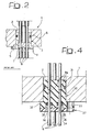
- Figure 2 of the annexed drawings illustrates a connector member according to the known art, used in tanks of the type referred to above.
- the reference number 1 designates a portion of the wall or closing plate of the tank, which has a through opening 2, in which there is mounted a steel bushing 3 provided with a flange 4 with holes 5 (only one of which may be seen in the figure) for engagement of fixing screws to the wall 1.
- the bushing 3 has, on its outer surface, a circumferential groove, in which there is received a seal ring 6, which ensures tightness between the bushing 3 and the wall 1.
- Set within the bushing 3 is a glass disk 7, obtained by fusion directly within the bushing 3 so as to make it adhere thereto.
- the disk 7 is also melted directly on four conductor pins 8 (only three of which are visible in the figure), which project axially from the opposite ends of the bushing 3 and from the opposite faces of the wall 1, each conductor pin being designed to be connected at its ends respectively to a line for internal connection to the tank and to a line for external connection to the tank.
- the glass molten directly within the steel bushing 3 and on the conductor pins 8 ensures hermetic sealing of the tank also in the presence of a pressure difference between the inside and the outside.
- the drawback of said known solution lies in the fact that the glass disk 7 is relatively brittle and is subject to the risk of cracking or fracturing resulting, for example, from thermal shock or possible careless manipulation of the tank or its components, particularly in the assembly and installation step. For instance, the operator responsible for installation can inadvertently deform one or more of the conductor pins 8 during their electrical connection to the respective connection terminals, with consequent mechanical stressing of the glass disk 7.
- US-A-3 922 477 discloses a connector member having the features of the preamble of claim 1.
- the purpose of the present invention is to provide a connector member for electrical connections through a wall of the fuel tank of a motor vehicle that will be free from the drawbacks mentioned above. It is, in particular, a purpose of the invention to provide a connector member that, on the one hand, will be able to guarantee hermetic sealing of the tank even in the presence of a pressure difference between the internal cavity of the tank and the external environment, and, on the other hand, will have a relatively simple and inexpensive structure, which is resistant and reliable in operation.
- the subject of the present invention is a connector member as set forth in claim 1.
- the body of the electrical connector is made of synthetic material directly moulded on the conductor pins and has seats for seal rings that guarantee tightness between the body of the connector and the seat in which it is received, as well as between the body of the connector and each conductor pin.
- the body of the connector has a cylindrical portion designed to be received in a through hole of a wall or closing plate of the tank, with an end flange provided with holes for engagement of fixing screws to said wall or plate.
- the cylindrical portion has a circumferential groove, which receives a seal ring designed to cooperate with the surface of the hole that functions as seat for the connector, whilst the end flange of the body of the connector has, on its front face, one or more seats for seal rings, which are each set between a respective conductor pin and the body of the connector.
- the seal rings associated to the various conductor pins are compressed axially by respective portions projecting within said cavities of an auxiliary covering plate, which is juxtaposed with the flange of the connector and secured thereto, for example, by means of the said screws for fixing the connector to the closing plate of the tank.
- the entire body of the connector consists of a synthetic or elastomer material directly moulded on the conductor pins and designed to ensure tightness both in an area corresponding to the surface of contact between the conductor pins and the body of the connector, and in an area corresponding to the surface of contact between the body of the connector and the wall of the hole in the closing plate of the tank that functions as seat for the connector itself.
- an auxiliary plate that is secured to the plate of the tank in order to set the body of the connector under a compressive load in its seat within the plate of the tank, so as to guarantee that it will be able to perform the function of seal in an optimal way.
- the electrical cable-lead connector of the invention is able, on the one hand, to ensure efficient electrical connection of the electrical components arranged within the tank with the external electrical lines and, on the other hand, to guarantee hermetic sealing of the tank also in the presence of major pressure jumps between the internal cavity of the tank and the external environment.
- the structure of the electrical connector according to the invention is moreover relatively simple and inexpensive to produce.
- the device according to the invention is not subject to the risks of failure that occur, instead, in the case of the known art on account of the fragility of the element made of glass described above.
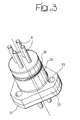
- the reference number 101 designates as a whole an LPG fuel tank built according to the known art, for supplying LPG to a plurality of injectors I associated to the various cylinders of the engine.
- the tank 101 has a hollow structure 102 built so as to guarantee tightness at the working pressures expected for a system of the type in question.
- the hollow structure 102 has a top opening closed by a service flange 103 carrying the various connector elements and providing connection of the tank to the supply system.
- the tank 101 has a first through opening 104, through which there is installed the structure of an assembly 105 connected to a line 106 for delivery of the LPG to a distribution manifold or rail 107, which distributes the LPG between the various injectors I.
- the assembly 105 includes a shut-off solenoid valve 108, which is designed to close, so interrupting communication of the tank with the outside environment in pre-determined emergency conditions, as well as a flow-limiting valve 109.
- the assembly 105 receives the LPG through the line 110 from the pump 111 controlled by an electric motor 111a, the structure of which is connected by means of a connection element 112 to the service flange 103.
- Installation of the pump 111 can in any case be carried out in any other way, as will be indicated also in what follows.
- the electrical supply of the solenoid valve 8, of the pump 111, and of the sensor 113 is guaranteed by an electrical connector 114, which is mounted via a through opening 115 of the service flange 103.
- the present invention relates to new embodiments of said connector.
- the flange 103 moreover has a further through opening 116, within which is installed an assembly 117 including two valves 118, 119.
- the valve 118 is a return valve, which is connected to a line 120 for flow back into the tank of the LPG supplied in excess to the rail 107.
- the valve 119 is the valve used for filling the tank and is associated to a further level-sensor 121.
- a safety valve 122 Associated to the flange 103 is moreover a safety valve 122, which prevents the pressure within the tank from exceeding a pre-determined threshold value.
- Figure 1 shows a traditional solution of tank, in which the flange 103 has through holes traversed by the various components described previously.
- the present invention could also be made with a tank having an innovative structure that has formed the subject of the preceding Italian patent application No. TO2001A000360 in the name of the present applicant, in which at least some of the aforesaid components are fixed to the bottom surface of the plate, without passing through it.
- the electrical connector comprises a body 30 made of synthetic material, for example thermoplastic material, which is moulded directly onto the conductor pins 8.
- the latter have portions 8a of small cross section, around which there is also engaged the material of the body 30.
- the body 30 of the connector has a cylindrical portion, which is designed to be received in the hole 2 of the plate 1 and has a circumferential groove, in which a seal ring 31 is mounted that ensures the seal between the wall of the body 30 and the wall of the hole 2.
- the body 30 moreover incorporates, in a single piece, a flange 32 with holes 33 for engagement of fixing screws (not illustrated) to the plate 1.
- the flange 32 On its front face, the flange 32 has axial cavities 34, each of which is traversed by a respective conductor pin 8.
- a seal ring 35 is set between each conductor pin 8 and the wall of the respective cavity 34, with the purpose of guaranteeing tightness also in the presence of a pressure jump between the surface of each conductor pin 8 and the body 30 of the connector.
- each seal ring 35 is pre-loaded axially in so far as it is pressed by a respective projecting portion 36 of a covering plate 37, which is juxtaposed with the flange 32 and is fixed thereto by means of the same fixing screws that secure the flange to the plate 1.
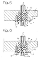
- Figures 5-8 illustrate four variants of a second embodiment of the invention, which differs from the one illustrated in Figures 3 and 4 in that it does not comprise seal rings, in so far as it is the very body of the connector that also performs the function of seal. Also in said figures, the parts corresponding to the ones of the figures already described above are designated by the same reference numbers.
- the body 30 of the connector consists of a cylindrical block made of elastomer material received in a respective seat, defined by the wall of the hole 2 and pressed axially against an annular contrast of the hole 2 by a plate 37 fixed to the plate 1 by means of screws 38.
- the conductor pins 8 have, in addition to the restricted sections 8a, also portions with a labyrinth profile 8b, for the purpose of improving further the seal between the body 30 and the pins 8.
- it is the very body 30, which is made of elastomer material, that ensures tightness also in the presence of a pressure jump.
- the covering plate 37 also guarantees the stability of the connection between the plate 1 and the body 30 during manipulation of the plate 1 in the installation stage.
- Figure 6 illustrates a solution substantially corresponding to that of Figure 4 except that, in this case, the plate 1 has, on its face facing the outside of the tank, four separate holes communicating with a seat of the body 30, through which there are engaged four protuberances 30a of the body 30. Said construction is more complex as compared to that of Figure 5, but safer from the standpoint of insulation of the conductor pins.
- the covering plate 37 has the same function already illustrated in Figure 4 and is preferably made, as already in the case of Figure 5, of plastic material.
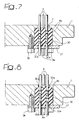
- Figure 7 illustrates a further variant that is substantially similar to that of Figure 6, with the single difference that, in this case, the four protuberances 30a are provided on the opposite end of the body 30 and engage four corresponding holes made in the covering plate 37, which in this case is preferably made of metal material.
- Figure 8 is substantially the result of a combination of the variants of Figures 6 and 7, with protuberances 30a provided on both ends of the body 30 for engaging respective holes made both in the plate 1 and in the covering plate 37.
Landscapes
- Engineering & Computer Science (AREA)
- Mechanical Engineering (AREA)
- General Engineering & Computer Science (AREA)
- Filling Or Discharging Of Gas Storage Vessels (AREA)
- Cooling, Air Intake And Gas Exhaust, And Fuel Tank Arrangements In Propulsion Units (AREA)
- Connector Housings Or Holding Contact Members (AREA)
- Organic Insulating Materials (AREA)
- Connections Effected By Soldering, Adhesion, Or Permanent Deformation (AREA)
- Cable Accessories (AREA)
Claims (7)
- Anschlussvorrichtung für durch eine Wand (1) des Kraftstofftanks (101) eines motorbetriebenen Fahrzeugs durchgeführten elektrischen Anschlüsse, insbesondere für einen Flüssiggas-Kraftstofftank oder dergleichen, der mit einem Druck innerhalb des Tanks betrieben werden kann, der höher ist als der Außendruck; die ein Isolierteil (30) umfasst, das zumindest teilweise aus synthetischem Material oder gummiartigem Material hergestellt ist, in das ein oder mehrere von den gegenüber liegenden Enden des Isolierteils (30) hervor stehende Leiterstifte (8) eingelassen sind;
dadurch gekennzeichnet, dass das Isolierteil (30) der Anschlussvorrichtung in einer Durchgangsbohrung (2) einer Wand oder Platte (1) des Tanks (101) angebracht werden kann; und dadurch, dass die Anschlussvorrichtung des Weiteren eine Zusatzplatte (37) umfasst, die durch Schrauben (38) an der Wand oder Platte (1) des Tanks auf der Seite desselben, die zu der Innenseite des Tanks (101) gerichtet ist, befestigt wird, um eine Druckbelastung entlang der Achse der Bohrung (2) auf das Isolierteil (30) des Steckverbinders oder Teilen desselben aufzubringen, wenn das Isolierteil (30) in seinem Sitz innerhalb der Bohrung (2) der Wand oder Platte (1) des Tanks angebracht worden ist, wodurch die Abdichtung verbessert wird. - Anschlussvorrichtung nach Anspruch 1, dadurch gekennzeichnet, dass das Isolierteil (30) des Steckverbinders aus synthetischem Material hergestellt ist und einen Teil aufweist, der in der oben genannten Durchgangsbohrung (2) der Wand oder Platte (1) des Tanks aufgenommen werden kann, wobei der Teil eine Umfangsnut für einen Dichtungsring (31) und einen Abschlussbund (32) aufweist, der mit Bohrungen (33) zum Eingriff von Stellschrauben mit der Wand oder Platte des Tanks versehen ist, der Bund (32) vordere Hohlräume (34) aufweist, die jeweils von einem entsprechenden Leiterstift (8) durchzogen sind, mit einem Dichtungsring (35), der innerhalb jedes der axialen Hohlräume (34) zwischen dem entsprechenden Leiterstift (8) und der Wand des Hohlraums (34) angebracht ist; und dadurch, dass die Zusatzplatte (37) über dem Bund (32) angebracht ist; die in den vorderen Hohlräumen des Bundes (32) angebrachten Dichtungsringe (35) in axialer Richtung durch Abschnitte (36), die von der Zusatzplatte (37) hervor stehen, gepresst werden.
- Anschlussvorrichtung nach Anspruch 2, dadurch gekennzeichnet, dass die Zusatzplatte (37) Öffnungen aufweist, die den Öffnungen (36) des Bundes (32) entsprechen, um eine Befestigung an dem Isolierteil (30) des Steckverbinders durch die gleichen Schrauben zu ermöglichen, die den Steckverbinder mit der Wand oder Platte (1) des Tanks befestigen.
- Anschlussvorrichtung nach Anspruch 1, dadurch gekennzeichnet, dass das Isolierteil (30) des Steckverbinders aus gummiartigem Material hergestellt ist und auch die Dichtungsfunktion ausführt; und dadurch, dass das Isolierteil (30) die Form eines zylindrischen Blocks aufweist, der in der Bohrung (2) aufgenommen ist und durch die Zusatzplatte (37) gegen ein ringförmiges Gegenstück, das durch die Fläche der Bohrung (2) gebildet wird, in axialer Richtung gepresst wird.
- Anschlussvorrichtung nach einem der vorhergehenden Ansprüche, dadurch gekennzeichnet, dass die oben genannten Leiterstifte (8) Abschnitte mit veränderlichem Querschnitt aufweisen, um die Verbindung zwischen den Stiften und dem an ihnen angeformten Isolierteil des Steckverbinders zu verbessern.
- Anschlussvorrichtung nach Anspruch 4, dadurch gekennzeichnet, dass das aus gummiartigem Kunststoff hergestellte Isolierteil (30) zumindest an einem seiner Enden axiale Ausstülpungen (30a) aufweist, die in einem Abstand voneinander eingerichtet sind, wobei jede einen entsprechenden Leiterstift (8) umgibt, und die jeweils in einem entsprechenden Sitz der Seitenwand oder Platte (1) der Zusatzplatte (37) aufgenommen sind.
- Kraftstofftank für ein motorbetriebenes Fahrzeug, insbesondere ein Flüssiggas-Kraftstofftank, umfassend ein hohles Isolierteil, das zumindest ein elektrisches Bauteil enthält und eine durch eine Abdeckplatte (1) geschlossene Öffnung aufweist, der Kraftstofftank dadurch gekennzeichnet ist, dass die Platte (1) zumindest eine Durchgangsbohrung (2) aufweist, in der eine Anschlussvorrichtung gemäß einem oder mehreren der vorhergehenden Ansprüche aufgenommen ist.
Applications Claiming Priority (2)
| Application Number | Priority Date | Filing Date | Title |
|---|---|---|---|
| IT000230A ITTO20030230A1 (it) | 2003-03-27 | 2003-03-27 | Organo connettore per collegamenti elettrici attraverso |
| ITTO20030230 | 2003-03-27 |
Publications (3)
| Publication Number | Publication Date |
|---|---|
| EP1471302A2 EP1471302A2 (de) | 2004-10-27 |
| EP1471302A3 EP1471302A3 (de) | 2006-09-06 |
| EP1471302B1 true EP1471302B1 (de) | 2007-08-08 |
Family
ID=32948216
Family Applications (1)
| Application Number | Title | Priority Date | Filing Date |
|---|---|---|---|
| EP04002647A Expired - Lifetime EP1471302B1 (de) | 2003-03-27 | 2004-02-06 | Anschlussvorrichtung für durch die Behälterwand eines Treibstoffbehälters durchgeführten elektrischen Anschlüsse, insbesondere für den Flüssiggasbehälter eines motorbetriebenen Fahrzeugs |
Country Status (7)
| Country | Link |
|---|---|
| US (1) | US7071416B2 (de) |
| EP (1) | EP1471302B1 (de) |
| AT (1) | ATE369523T1 (de) |
| AU (1) | AU2004200807A1 (de) |
| CA (1) | CA2457326A1 (de) |
| DE (1) | DE602004007973D1 (de) |
| IT (1) | ITTO20030230A1 (de) |
Families Citing this family (22)
| Publication number | Priority date | Publication date | Assignee | Title |
|---|---|---|---|---|
| JP4263528B2 (ja) * | 2003-05-07 | 2009-05-13 | スガツネ工業株式会社 | 配線挿通孔用係嵌キャップ |
| GB2440373A (en) * | 2006-07-26 | 2008-01-30 | Otter Controls Ltd | A cordless electrical connector with a seal |
| DE102007004656A1 (de) * | 2007-01-25 | 2008-07-31 | Abb Technology Ag | Isolator |
| US8399762B2 (en) * | 2007-06-11 | 2013-03-19 | Solibro Research Ab | Electrical feed-through |
| JP4404920B2 (ja) * | 2007-08-10 | 2010-01-27 | トヨタ自動車株式会社 | コネクタ接続構造およびコネクタ接続方法ならびに車両 |
| FR2931312B1 (fr) * | 2008-05-16 | 2010-09-03 | Thales Sa | Passe-fil etanche et procede de realisation du passe-fil |
| WO2009143123A2 (en) * | 2008-05-19 | 2009-11-26 | Emerson Electric Co. | Electric power terminal feed-through |
| US8869775B2 (en) * | 2010-02-09 | 2014-10-28 | Denso Corporation | Fuel supply apparatus |
| JP5521777B2 (ja) * | 2010-05-26 | 2014-06-18 | 住友電装株式会社 | 電線引出孔のシール構造 |
| CN103124485B (zh) * | 2011-11-21 | 2015-11-25 | 神讯电脑(昆山)有限公司 | 线材防液结构及其电子装置 |
| TWI511388B (zh) * | 2012-12-07 | 2015-12-01 | Wistron Corp | 具有防水與避震功能之連接器的電子裝置 |
| CN104078781B (zh) * | 2014-07-07 | 2016-07-06 | 南通大地电气有限公司 | 气门室线束 |
| EP3168075A1 (de) * | 2015-11-16 | 2017-05-17 | Plastic Omnium Advanced Innovation and Research | Tank mit einem steckverbinder und verfahren zum anschliessen einer elektrischen vorrichtung in einem tank |
| JP2018107017A (ja) * | 2016-12-27 | 2018-07-05 | 住友電装株式会社 | コネクタ |
| WO2019215036A1 (de) | 2018-05-08 | 2019-11-14 | Brose Fahrzeugteile GmbH & Co. Kommanditgesellschaft, Würzburg | ELEKTRONIKEINHEIT UND ELEKTRISCHE FLUIDPUMPE SOWIE VERSCHLIEßELEMENT |
| DE102019130743A1 (de) * | 2019-11-14 | 2021-05-20 | Te Connectivity Germany Gmbh | HF-Terminal für einen HF-Verbinder, sowie Verfahren zur Gütesteigerung einer Signalintegrität eines männlichen HF-Verbinders oder einer HF-Steckverbindung |
| GB2599117B (en) * | 2020-09-24 | 2023-04-12 | Delphi Tech Ip Ltd | Electrical connector |
| DE102020126128A1 (de) | 2020-10-06 | 2022-04-07 | Geiger Automotive Gmbh | Modulare Steckereinheit an Bauteilen |
| US11870179B2 (en) * | 2021-04-09 | 2024-01-09 | Te Connectivity Solutions Gmbh | Pin assembly having a seal |
| CA3229300A1 (en) * | 2021-08-17 | 2023-02-23 | Ebara Corporation | Power feeding apparatus and power feeding method for submersible pump |
| DE102023201898A1 (de) | 2023-03-02 | 2024-09-05 | Robert Bosch Gesellschaft mit beschränkter Haftung | Stecker-Sensor-Baugruppe, Gehäuse für ein Tankventil oder einen Tankendstopfen mit einer Stecker-Sensor-Baugruppe, Tankventil sowie Tankendstopfen |
| DE102023202542A1 (de) * | 2023-03-22 | 2024-09-26 | Robert Bosch Gesellschaft mit beschränkter Haftung | Anschlussbaugruppe für ein Tankventil, Tankventil mit Anschlussbaugruppe |
Family Cites Families (17)
| Publication number | Priority date | Publication date | Assignee | Title |
|---|---|---|---|---|
| US3922477A (en) * | 1971-08-30 | 1975-11-25 | Viking Industries | Through-wall conductor seal |
| EP0033035B1 (de) * | 1979-12-26 | 1984-03-07 | Sumitomo Electric Industries Limited | Flüssigkeitsdichte, elektrische Kupplungsvorrichtung |
| SE430191B (sv) * | 1982-02-12 | 1983-10-24 | Lyckeaborgs Bruk Ab | Lengstrycktet genomforing |
| JP2766558B2 (ja) * | 1991-02-14 | 1998-06-18 | 矢崎総業株式会社 | 油洩れ防止用電線保持ケース |
| US5500490A (en) * | 1994-01-10 | 1996-03-19 | Borg-Warner Automotive, Inc. | Method and apparatus for forming leakproof feed-through connector |
| US5631445A (en) * | 1994-10-07 | 1997-05-20 | Ford Motor Company | Automotive fuel tank electrical fitting |
| JPH08210083A (ja) | 1995-02-02 | 1996-08-13 | Houshiyou:Kk | 地中配管工事における坑口止水装置及び坑口止水方法 |
| ES2105917T3 (es) | 1995-02-03 | 1997-10-16 | Fiat Ricerche | Motor de combustion interna adaptado para funcionar selectivamente con inyeccion de gasolina o con glp. |
| DE19540022A1 (de) * | 1995-10-27 | 1997-04-30 | Bosch Gmbh Robert | Anordnung zum Abdichten einer Kabeldurchführung |
| DE19728370A1 (de) * | 1997-07-03 | 1999-01-07 | Bosch Gmbh Robert | Kabeldurchführung für Anschlußkabel eines Gasmeßfühlers |
| IT1296634B1 (it) | 1997-12-12 | 1999-07-14 | C R F Societa Conosrtile Per A | Serbatoio di gpl per un motore a combustione interna atto ad operare selettivamente con benzina e con gpl |
| US6305989B1 (en) * | 1999-08-30 | 2001-10-23 | Emerson Electric Co. | Connector block for a terminal assembly |
| US6213101B1 (en) * | 1999-10-29 | 2001-04-10 | James W. Numbers | Method and apparatus for blocking fluid and fuel vapors |
| US6582251B1 (en) * | 2000-04-28 | 2003-06-24 | Greene, Tweed Of Delaware, Inc. | Hermetic electrical connector and method of making the same |
| US6555754B2 (en) * | 2001-01-18 | 2003-04-29 | Walbro Corporation | Automotive fuel tank electrical fitting |
| US6452099B1 (en) * | 2001-02-08 | 2002-09-17 | Dynetek Industries Ltd. | Electric signal pass through arrangement |
| ITTO20010360A1 (it) | 2001-04-13 | 2002-10-13 | Fiat Ricerche | Serbatoio per un sistema di alimentazione ad iniezione di gpl per motori a combustione interna. |
-
2003
- 2003-03-27 IT IT000230A patent/ITTO20030230A1/it unknown
-
2004
- 2004-02-06 AT AT04002647T patent/ATE369523T1/de not_active IP Right Cessation
- 2004-02-06 EP EP04002647A patent/EP1471302B1/de not_active Expired - Lifetime
- 2004-02-06 DE DE602004007973T patent/DE602004007973D1/de not_active Expired - Lifetime
- 2004-02-11 CA CA002457326A patent/CA2457326A1/en not_active Abandoned
- 2004-02-27 AU AU2004200807A patent/AU2004200807A1/en not_active Abandoned
- 2004-03-15 US US10/799,887 patent/US7071416B2/en not_active Expired - Fee Related
Also Published As
| Publication number | Publication date |
|---|---|
| ATE369523T1 (de) | 2007-08-15 |
| EP1471302A2 (de) | 2004-10-27 |
| US20040188121A1 (en) | 2004-09-30 |
| US7071416B2 (en) | 2006-07-04 |
| CA2457326A1 (en) | 2004-09-27 |
| EP1471302A3 (de) | 2006-09-06 |
| DE602004007973D1 (de) | 2007-09-20 |
| AU2004200807A1 (en) | 2004-10-14 |
| ITTO20030230A1 (it) | 2004-09-28 |
Similar Documents
| Publication | Publication Date | Title |
|---|---|---|
| EP1471302B1 (de) | Anschlussvorrichtung für durch die Behälterwand eines Treibstoffbehälters durchgeführten elektrischen Anschlüsse, insbesondere für den Flüssiggasbehälter eines motorbetriebenen Fahrzeugs | |
| US5511527A (en) | Fuel rail assembly with crossover hose | |
| KR100584492B1 (ko) | 연료분사밸브의 조립용 조립장치 | |
| CA2071252C (en) | Natural gas cylinder fitting and solenoid valve | |
| RU2602014C2 (ru) | Улучшенная бобышка для композитного резервуара | |
| US6474565B1 (en) | Fuel injection valve | |
| KR100195462B1 (ko) | 브레이크 유압제어기 | |
| CN102165233B (zh) | 油控制阀安装构造 | |
| CA2159390A1 (en) | Automotive fuel tank electrical fitting | |
| US20080283789A1 (en) | Valve for controlling the flow of fluid | |
| US20110006137A1 (en) | Sealed electric feedthrough | |
| EP1193391B1 (de) | Spulensystem mit einer Struktur zum Verhindern von Fluidleckage | |
| JP2005098275A (ja) | 燃料噴射装置 | |
| US8598767B2 (en) | Piezoelectric actuator | |
| US10830371B2 (en) | Electromagnetic valve and use thereof | |
| US6691888B2 (en) | Fuel tank | |
| CN104169566A (zh) | 组件 | |
| JP2009293555A (ja) | シリンダヘッドカバー | |
| CN101124399B (zh) | 燃料喷射阀 | |
| US11053904B2 (en) | Fuel injector | |
| US7186143B2 (en) | Sealing apparatus assembly for sealing a piezoactuator and method for sealing a piezoactuator | |
| KR100741672B1 (ko) | 차량용 인젝터의 설치구조 | |
| CN102047355A (zh) | 用于电磁阀的磁铁组件 | |
| KR102494463B1 (ko) | 고기밀성 압력용기 | |
| AU2007304380A1 (en) | Alternative fuel injector for dual fuel systems |
Legal Events
| Date | Code | Title | Description |
|---|---|---|---|
| PUAI | Public reference made under article 153(3) epc to a published international application that has entered the european phase |
Free format text: ORIGINAL CODE: 0009012 |
|
| AK | Designated contracting states |
Kind code of ref document: A2 Designated state(s): AT BE BG CH CY CZ DE DK EE ES FI FR GB GR HU IE IT LI LU MC NL PT RO SE SI SK TR |
|
| AX | Request for extension of the european patent |
Extension state: AL LT LV MK |
|
| PUAL | Search report despatched |
Free format text: ORIGINAL CODE: 0009013 |
|
| AK | Designated contracting states |
Kind code of ref document: A3 Designated state(s): AT BE BG CH CY CZ DE DK EE ES FI FR GB GR HU IE IT LI LU MC NL PT RO SE SI SK TR |
|
| AX | Request for extension of the european patent |
Extension state: AL LT LV MK |
|
| RIC1 | Information provided on ipc code assigned before grant |
Ipc: H01R 13/74 20060101ALI20060803BHEP Ipc: F17C 13/04 20060101AFI20040907BHEP Ipc: H01R 13/52 20060101ALI20060803BHEP |
|
| 17P | Request for examination filed |
Effective date: 20060906 |
|
| 17Q | First examination report despatched |
Effective date: 20061020 |
|
| GRAP | Despatch of communication of intention to grant a patent |
Free format text: ORIGINAL CODE: EPIDOSNIGR1 |
|
| RIN1 | Information on inventor provided before grant (corrected) |
Inventor name: RICCO, MARIO Inventor name: DE MATTHAEIS, SISTO LUIGI Inventor name: AMORESE, CLAUDIO Inventor name: DE MICHELE, ONOFRIO Inventor name: SATRIANO, ANNUNZIATA ANNA |
|
| AKX | Designation fees paid |
Designated state(s): AT BE BG CH CY CZ DE DK EE ES FI FR GB GR HU IE IT LI LU MC NL PT RO SE SI SK TR |
|
| GRAS | Grant fee paid |
Free format text: ORIGINAL CODE: EPIDOSNIGR3 |
|
| GRAA | (expected) grant |
Free format text: ORIGINAL CODE: 0009210 |
|
| AK | Designated contracting states |
Kind code of ref document: B1 Designated state(s): AT BE BG CH CY CZ DE DK EE ES FI FR GB GR HU IE IT LI LU MC NL PT RO SE SI SK TR |
|
| REG | Reference to a national code |
Ref country code: GB Ref legal event code: FG4D |
|
| REG | Reference to a national code |
Ref country code: CH Ref legal event code: EP |
|
| REG | Reference to a national code |
Ref country code: IE Ref legal event code: FG4D |
|
| REF | Corresponds to: |
Ref document number: 602004007973 Country of ref document: DE Date of ref document: 20070920 Kind code of ref document: P |
|
| PG25 | Lapsed in a contracting state [announced via postgrant information from national office to epo] |
Ref country code: ES Free format text: LAPSE BECAUSE OF FAILURE TO SUBMIT A TRANSLATION OF THE DESCRIPTION OR TO PAY THE FEE WITHIN THE PRESCRIBED TIME-LIMIT Effective date: 20071119 Ref country code: NL Free format text: LAPSE BECAUSE OF FAILURE TO SUBMIT A TRANSLATION OF THE DESCRIPTION OR TO PAY THE FEE WITHIN THE PRESCRIBED TIME-LIMIT Effective date: 20070808 Ref country code: FI Free format text: LAPSE BECAUSE OF FAILURE TO SUBMIT A TRANSLATION OF THE DESCRIPTION OR TO PAY THE FEE WITHIN THE PRESCRIBED TIME-LIMIT Effective date: 20070808 Ref country code: BG Free format text: LAPSE BECAUSE OF FAILURE TO SUBMIT A TRANSLATION OF THE DESCRIPTION OR TO PAY THE FEE WITHIN THE PRESCRIBED TIME-LIMIT Effective date: 20071108 |
|
| NLV1 | Nl: lapsed or annulled due to failure to fulfill the requirements of art. 29p and 29m of the patents act | ||
| REG | Reference to a national code |
Ref country code: CH Ref legal event code: PL |
|
| PG25 | Lapsed in a contracting state [announced via postgrant information from national office to epo] |
Ref country code: AT Free format text: LAPSE BECAUSE OF FAILURE TO SUBMIT A TRANSLATION OF THE DESCRIPTION OR TO PAY THE FEE WITHIN THE PRESCRIBED TIME-LIMIT Effective date: 20070808 Ref country code: LI Free format text: LAPSE BECAUSE OF FAILURE TO SUBMIT A TRANSLATION OF THE DESCRIPTION OR TO PAY THE FEE WITHIN THE PRESCRIBED TIME-LIMIT Effective date: 20070808 Ref country code: CH Free format text: LAPSE BECAUSE OF FAILURE TO SUBMIT A TRANSLATION OF THE DESCRIPTION OR TO PAY THE FEE WITHIN THE PRESCRIBED TIME-LIMIT Effective date: 20070808 |
|
| PG25 | Lapsed in a contracting state [announced via postgrant information from national office to epo] |
Ref country code: BE Free format text: LAPSE BECAUSE OF FAILURE TO SUBMIT A TRANSLATION OF THE DESCRIPTION OR TO PAY THE FEE WITHIN THE PRESCRIBED TIME-LIMIT Effective date: 20070808 |
|
| EN | Fr: translation not filed | ||
| PG25 | Lapsed in a contracting state [announced via postgrant information from national office to epo] |
Ref country code: GR Free format text: LAPSE BECAUSE OF FAILURE TO SUBMIT A TRANSLATION OF THE DESCRIPTION OR TO PAY THE FEE WITHIN THE PRESCRIBED TIME-LIMIT Effective date: 20071109 Ref country code: DK Free format text: LAPSE BECAUSE OF FAILURE TO SUBMIT A TRANSLATION OF THE DESCRIPTION OR TO PAY THE FEE WITHIN THE PRESCRIBED TIME-LIMIT Effective date: 20070808 |
|
| PG25 | Lapsed in a contracting state [announced via postgrant information from national office to epo] |
Ref country code: PT Free format text: LAPSE BECAUSE OF FAILURE TO SUBMIT A TRANSLATION OF THE DESCRIPTION OR TO PAY THE FEE WITHIN THE PRESCRIBED TIME-LIMIT Effective date: 20080108 Ref country code: SK Free format text: LAPSE BECAUSE OF FAILURE TO SUBMIT A TRANSLATION OF THE DESCRIPTION OR TO PAY THE FEE WITHIN THE PRESCRIBED TIME-LIMIT Effective date: 20070808 Ref country code: CZ Free format text: LAPSE BECAUSE OF FAILURE TO SUBMIT A TRANSLATION OF THE DESCRIPTION OR TO PAY THE FEE WITHIN THE PRESCRIBED TIME-LIMIT Effective date: 20070808 |
|
| PLBE | No opposition filed within time limit |
Free format text: ORIGINAL CODE: 0009261 |
|
| STAA | Information on the status of an ep patent application or granted ep patent |
Free format text: STATUS: NO OPPOSITION FILED WITHIN TIME LIMIT |
|
| PG25 | Lapsed in a contracting state [announced via postgrant information from national office to epo] |
Ref country code: SE Free format text: LAPSE BECAUSE OF FAILURE TO SUBMIT A TRANSLATION OF THE DESCRIPTION OR TO PAY THE FEE WITHIN THE PRESCRIBED TIME-LIMIT Effective date: 20071108 Ref country code: RO Free format text: LAPSE BECAUSE OF FAILURE TO SUBMIT A TRANSLATION OF THE DESCRIPTION OR TO PAY THE FEE WITHIN THE PRESCRIBED TIME-LIMIT Effective date: 20070808 |
|
| 26N | No opposition filed |
Effective date: 20080509 |
|
| PG25 | Lapsed in a contracting state [announced via postgrant information from national office to epo] |
Ref country code: DE Free format text: LAPSE BECAUSE OF FAILURE TO SUBMIT A TRANSLATION OF THE DESCRIPTION OR TO PAY THE FEE WITHIN THE PRESCRIBED TIME-LIMIT Effective date: 20071109 |
|
| GBPC | Gb: european patent ceased through non-payment of renewal fee |
Effective date: 20080206 |
|
| PG25 | Lapsed in a contracting state [announced via postgrant information from national office to epo] |
Ref country code: MC Free format text: LAPSE BECAUSE OF NON-PAYMENT OF DUE FEES Effective date: 20080228 |
|
| PG25 | Lapsed in a contracting state [announced via postgrant information from national office to epo] |
Ref country code: EE Free format text: LAPSE BECAUSE OF FAILURE TO SUBMIT A TRANSLATION OF THE DESCRIPTION OR TO PAY THE FEE WITHIN THE PRESCRIBED TIME-LIMIT Effective date: 20070808 Ref country code: IE Free format text: LAPSE BECAUSE OF NON-PAYMENT OF DUE FEES Effective date: 20080206 |
|
| PG25 | Lapsed in a contracting state [announced via postgrant information from national office to epo] |
Ref country code: GB Free format text: LAPSE BECAUSE OF NON-PAYMENT OF DUE FEES Effective date: 20080206 Ref country code: SI Free format text: LAPSE BECAUSE OF FAILURE TO SUBMIT A TRANSLATION OF THE DESCRIPTION OR TO PAY THE FEE WITHIN THE PRESCRIBED TIME-LIMIT Effective date: 20070808 |
|
| PG25 | Lapsed in a contracting state [announced via postgrant information from national office to epo] |
Ref country code: CY Free format text: LAPSE BECAUSE OF FAILURE TO SUBMIT A TRANSLATION OF THE DESCRIPTION OR TO PAY THE FEE WITHIN THE PRESCRIBED TIME-LIMIT Effective date: 20070808 |
|
| PG25 | Lapsed in a contracting state [announced via postgrant information from national office to epo] |
Ref country code: LU Free format text: LAPSE BECAUSE OF NON-PAYMENT OF DUE FEES Effective date: 20080206 Ref country code: HU Free format text: LAPSE BECAUSE OF FAILURE TO SUBMIT A TRANSLATION OF THE DESCRIPTION OR TO PAY THE FEE WITHIN THE PRESCRIBED TIME-LIMIT Effective date: 20080209 |
|
| PG25 | Lapsed in a contracting state [announced via postgrant information from national office to epo] |
Ref country code: TR Free format text: LAPSE BECAUSE OF FAILURE TO SUBMIT A TRANSLATION OF THE DESCRIPTION OR TO PAY THE FEE WITHIN THE PRESCRIBED TIME-LIMIT Effective date: 20070808 |
|
| PG25 | Lapsed in a contracting state [announced via postgrant information from national office to epo] |
Ref country code: IT Free format text: LAPSE BECAUSE OF NON-PAYMENT OF DUE FEES Effective date: 20080229 |
|
| PG25 | Lapsed in a contracting state [announced via postgrant information from national office to epo] |
Ref country code: FR Free format text: LAPSE BECAUSE OF FAILURE TO SUBMIT A TRANSLATION OF THE DESCRIPTION OR TO PAY THE FEE WITHIN THE PRESCRIBED TIME-LIMIT Effective date: 20080404 |