EP1472006B1 - Anlage zum spritzen eines beschichtungsproudkts und verfahren zu ihrer reinigung - Google Patents
Anlage zum spritzen eines beschichtungsproudkts und verfahren zu ihrer reinigung Download PDFInfo
- Publication number
- EP1472006B1 EP1472006B1 EP03718841A EP03718841A EP1472006B1 EP 1472006 B1 EP1472006 B1 EP 1472006B1 EP 03718841 A EP03718841 A EP 03718841A EP 03718841 A EP03718841 A EP 03718841A EP 1472006 B1 EP1472006 B1 EP 1472006B1
- Authority
- EP
- European Patent Office
- Prior art keywords
- tank
- product
- sprayer
- coating product
- robot
- Prior art date
- Legal status (The legal status is an assumption and is not a legal conclusion. Google has not performed a legal analysis and makes no representation as to the accuracy of the status listed.)
- Expired - Lifetime
Links
Images



Classifications
-
- B—PERFORMING OPERATIONS; TRANSPORTING
- B05—SPRAYING OR ATOMISING IN GENERAL; APPLYING FLUENT MATERIALS TO SURFACES, IN GENERAL
- B05B—SPRAYING APPARATUS; ATOMISING APPARATUS; NOZZLES
- B05B5/00—Electrostatic spraying apparatus; Spraying apparatus with means for charging the spray electrically; Apparatus for spraying liquids or other fluent materials by other electric means
- B05B5/16—Arrangements for supplying liquids or other fluent material
- B05B5/1608—Arrangements for supplying liquids or other fluent material the liquid or other fluent material being electrically conductive
- B05B5/1616—Arrangements for supplying liquids or other fluent material the liquid or other fluent material being electrically conductive and the arrangement comprising means for insulating a grounded material source from high voltage applied to the material
- B05B5/1625—Arrangements for supplying liquids or other fluent material the liquid or other fluent material being electrically conductive and the arrangement comprising means for insulating a grounded material source from high voltage applied to the material the insulating means comprising an intermediate container alternately connected to the grounded material source for filling, and then disconnected and electrically insulated therefrom
-
- B—PERFORMING OPERATIONS; TRANSPORTING
- B05—SPRAYING OR ATOMISING IN GENERAL; APPLYING FLUENT MATERIALS TO SURFACES, IN GENERAL
- B05B—SPRAYING APPARATUS; ATOMISING APPARATUS; NOZZLES
- B05B12/00—Arrangements for controlling delivery; Arrangements for controlling the spray area
- B05B12/14—Arrangements for controlling delivery; Arrangements for controlling the spray area for supplying a selected one of a plurality of liquids or other fluent materials or several in selected proportions to a spray apparatus, e.g. to a single spray outlet
-
- B—PERFORMING OPERATIONS; TRANSPORTING
- B05—SPRAYING OR ATOMISING IN GENERAL; APPLYING FLUENT MATERIALS TO SURFACES, IN GENERAL
- B05B—SPRAYING APPARATUS; ATOMISING APPARATUS; NOZZLES
- B05B13/00—Machines or plants for applying liquids or other fluent materials to surfaces of objects or other work by spraying, not covered by groups B05B1/00 - B05B11/00
- B05B13/02—Means for supporting work; Arrangement or mounting of spray heads; Adaptation or arrangement of means for feeding work
- B05B13/04—Means for supporting work; Arrangement or mounting of spray heads; Adaptation or arrangement of means for feeding work the spray heads being moved during spraying operation
- B05B13/0431—Means for supporting work; Arrangement or mounting of spray heads; Adaptation or arrangement of means for feeding work the spray heads being moved during spraying operation with spray heads moved by robots or articulated arms, e.g. for applying liquid or other fluent material to three-dimensional [3D] surfaces
-
- B—PERFORMING OPERATIONS; TRANSPORTING
- B05—SPRAYING OR ATOMISING IN GENERAL; APPLYING FLUENT MATERIALS TO SURFACES, IN GENERAL
- B05B—SPRAYING APPARATUS; ATOMISING APPARATUS; NOZZLES
- B05B15/00—Details of spraying plant or spraying apparatus not otherwise provided for; Accessories
- B05B15/50—Arrangements for cleaning; Arrangements for preventing deposits, drying-out or blockage; Arrangements for detecting improper discharge caused by the presence of foreign matter
- B05B15/55—Arrangements for cleaning; Arrangements for preventing deposits, drying-out or blockage; Arrangements for detecting improper discharge caused by the presence of foreign matter using cleaning fluids
Definitions
- the invention relates to a projection installation coating product and a method of cleaning a such an installation
- the invention relates to an installation projection of coating products comprising at least a robot whose mobile part supports at least one projector and a coating product tank connected to power the projector.
- This installation is characterized in that the robot carries a second tank capable of being filled with a cleaning product, this second tank being connected to supply product cleaning the coating product tank, the projector and / or ducts connecting the tank to projector.
- the content of the second reservoir can be used to clean the product tank from coating, the headlamp and / or the associated ducts, the end of a coating product projection step, that is to say before the robot has positioned its projector and its reservoir relative to means located stationary and intended to supply it with coating.
- the travel time of the robot from its projection position to its position of filling in new coating product can be put at a profit to clean the product tank of coating, the projector and associated ducts from content of the second tank.
- the invention also relates to a cleaning method of an installation as described above and, more specifically, a method of cleaning an installation projection of coating products comprising a coating product tank and a projector associated, this tank and / or this projector being mounted on a multi-axis robot, characterized in that it comprises a step of feeding the tank, the projector and / or the ducts connecting the tank to the projector in cleaning products from a second tank mounted on the robot.
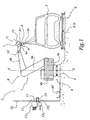
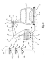
- an automaton or robot 1 is placed near a conveyor 2 transporting objects to be coated, in this case bodies 3 of motor vehicles.
- the robot 1 is of the multi-axis type and comprises a mobile frame 4 on a guide 5 extending parallel to the conveying direction X-X '.
- An arm 6 is supported by the chassis 4 and comprises a plurality of segments 6 a, 6 b, 6 c, articulated relative to each other.
- the chassis 4 comprises portions 4a and 4b articulated with respect to one another about an axis ZZ 'substantially vertical.
- the segment 6c of the arm 6 supports an assembly comprising a reservoir 7, a projector 8 and a plate 9 in which are formed ducts connecting the reservoir 7 to the projector 8, one of these ducts being shown in Figures 1 and 2 with the reference 91.
- the projector 8 is of the electrostatic type and is connected to a high voltage generator not shown.
- the product contained in the tank 7 can be a painting water soluble or a solvent-based paint.
- the projector 8 is used to project on the bodywork 3 of the product coating from the reservoir 7.
- a second tank 10 is mounted on the robot 1, close to the segment 6c and is connected, by conduits not shown, to the tank 7, the projector 8 and the plate 9.
- This tank 10 is intended to be filled with product
- the cleaning product which may be a solvent for the coating product contained in the reservoir 7.
- the nature of the cleaning product is adapted to the type of coating product passing through the elements 7 to 9.
- the tank 10 could be mounted on the plate 9 and / or attached to the tank 7.
- the contents of the tank 10 can be used to clean the elements 7, 8 and 9.
- This cleaning step can take place simultaneously moving the projector 8 from its position in the figure 1 to its position in Figure 2, that is to say in time mask.
- a box 20 of product collection of used cleaning is provided in cabin C, near the foot of the partition 12. This box allows to collect the product used to clean the terminal part 8a of the 8 and can be connected to a purge circuit for the evacuation of the used cleaning product.
- the reservoir 7 is provided on its outer surface with a first connector 71 intended to cooperate with a connector 11 stationed on a bulkhead 12 of the coating C in which the robot is installed.
- tank 7 is also provided with a second connector 72 intended to cooperate with a second connector 13 disposed in cabin C, near the connector 11.
- the connector 11 is connected by a conduit 11 1 to a unit 11 2 for changing the coating product that can supply the connector 11 in different coating products, depending on the nature of the product to be projected on the next body 3 arriving next robot 1.
- the connector 13 is, for its part, connected by a conduit 13 1 to a source 13 2 of cleaning product.
- the connector 11 is connected to the inside of the tank 7 while the connector 72 is connected to the inside of the tank 10.
- the tank 10 has a sufficient capacity to allow two cleanings successive stages of the tank 7, the projector 8 and the stage 9. In this case, the tank 10 may not be filled each time the tank is filled. 7. In a variant, the tank 10 may have a capacity allowing more two cleaning of the elements 7, 8 and 9.
- the robot 101 of this embodiment is arranged opposite a conveyor 102 on which car bodies 103 of motor vehicles.
- the robot 101 comprises a frame 104 movable on a guide 105 and an arm 106 comprising a plurality of segments 106 a, 106 b and 106 c.
- a tank 107 is mounted on the arm 106 c and is associated with an electrostatic sprayer 108 to which it is connected through a plate 109 in which are formed the ducts, which is shown with reference 191.
- a second tank 110 is mounted on the robot 101 to near the tank 107 and is intended to be filled in cleaning product, like the tank 10 of the first mode of realization.
- a third tank 120 is also mounted on the robot 101 near the tank 107 and is adapted to receive the cleaning residues elements 107, 108 and 109, except those corresponding to cleaning of the end part 108 of the projector 108, which can be spit out in the cabin because they are of very low volume.
- a box of the type of the box 20 of the first embodiment could be provided.
- the tanks 110 and 120 are, in practice, neighbors of the platinum 109.
- connectors 171 and 172 are provided on the reservoir 107 to cooperate with connectors 111 and 113 provided fixed station in the cabin C, the connectors 111 and 113 being respectively connected to a unit 111 2 of coating product change and a source 113 2 of cleaning product.
- a third connector 173 is provided on the reservoir 107 to cooperate with a connector 114 installed stationary on the partition 112 of the cabin C and connected by a conduit 114 1 to a purge 114 2 .
- the tank 107 can be brought opposite the connectors 111, 113 and 114, which makes it possible to fill the tanks 107 and 110 respectively with coating product and cleaning product and emptying the tank 120 towards the purge 114 2 .
- the robot 201 of this embodiment is arranged opposite a conveyor 202 on which pass bodies 203 of motor vehicles.
- the robot 201 comprises a frame 204 mounted on a guide 205 and an arm 206 comprising a plurality of segments 206 a, 206 b and 206 c.
- a tank 207 is mounted on the segment 206 and c is associated with an electrostatic sprayer 208 through ducts formed in a plate 209, a line appearing in Figure 5 with the reference 291.
- a reservoir 210 of cleaning product is provided on the robot 201 near the tank 207, as well as a tank 220 collection of cleaning residues of elements 207 to 209.
- Two connectors 271 and 272 are provided on the container 207 to respectively cooperate with stationary connectors 211 and 213 provided on the partition 212 of the cab C which is installed in the robot 201.
- the connector 211 is connected by a conduit 211 1 to a unit 211 2 of coating product change.
- the connector 213 is connected by a conduit 213 1 to a three-way valve 213 2 , itself connected by conduits 213 3 and 213 4 to a source 213 5 of cleaner and a purge 213 6 .
- the tanks 210 and 220 which are in practice adjacent to the plate 209, may have sufficient capacity to enable them not to be filled or purged at each connection of the reservoir 207 to the connector 211.
- the connectors 272 and 213 are used every other time to connect the source 213 5 and the tank 210, and every other time to put in communication the reservoir 220 and the purge 213 6 .
- the tanks 210 and 220 are respectively filled and emptied at each connection of the reservoir 207 to the source of coating products, the reservoir 210 being first filled from the source 213 5 , then the three-way valve 213 2 being switched to its second position where it allows the discharge of the contents of the tank 220 to the purge 213 6 .
- the spill of the contents of the reservoir 220 can take place before filling the tank 210.
- the second tanks 10, 110 and 210 of a according to the invention are advantageously piston tanks or diaphragm tanks deformable, which allows to control the flow of the product cleaning in the direction of the organs to be cleaned.
- the third tanks 120 or 220 can also be constituted by piston tanks or tanks with deformable membrane.
- the second tanks 10, 110 and 120 are mounted permanently or removably on the robots.
- the invention has been described with a multi-axis robot. It is however applicable regardless of the exact type of the robot, provided that a reservoir of coating and a tank of cleaning product are embedded on a moving part of this robot. He could be a reciprocator, a machine called “roof” or a so-called “lateral” machine.
Landscapes
- Engineering & Computer Science (AREA)
- Robotics (AREA)
- Spray Control Apparatus (AREA)
- Application Of Or Painting With Fluid Materials (AREA)
- Agricultural Chemicals And Associated Chemicals (AREA)
- Cleaning By Liquid Or Steam (AREA)
- Details Or Accessories Of Spraying Plant Or Apparatus (AREA)
Claims (22)
- Anlage zum Spritzen von Beschichtungsprodukt, mindestens einen Roboter umfassend, dessen bewegliches Teil mindestens einen Projektor und einen Behälter für Beschichtungsmaterial aufweist, der angeschlossen ist, um den Projektor zu versorgen,
dadurch gekennzeichnet, dass der Roboter (1 ; 101 ; 201) einen zweiten Behälter (10 ; 110 ; 210) trägt, der zur Befüllung mit Reinigungsprodukt geeignet ist, wobei der zweite Behälter verbunden ist, um den Behälter (7 ; 107 ; 207) für Beschichtungsprodukt, den Projektor (8 ; 108 ; 208) und/oder die den Behälter für Beschichtungsprodukt mit dem Projektor verbindenden Leitungen (91 ; 191 ; 291) mit Reinigungsprodukt zu versorgen. - Anlage nach Anspruch 1, dadurch gekennzeichnet, dass der zweite Behälter (10 ; 110 ; 210) ein Innenvolumen aufweist, das ihm erlaubt, eine Menge an Reinigungsprodukt aufzunehmen, die ausreicht, um den Behälter (7 ; 107 ; 207) für Beschichtungsprodukt, den Projektor (8 ; 108 ; 208) und/oder die Leitungen (91 ; 191 ; 291) mindestens zweimal zu reinigen.
- Anlage nach einem der vorhergehenden Ansprüche, dadurch gekennzeichnet, dass der zweite Behälter (10 ; 110 ; 210) in der Nähe des Behälters (7 ; 107 ; 207) für Beschichtungsprodukt an den Roboter (1 ; 101 ; 201) befestigt ist.
- Anlage nach einem der vorhergehenden Ansprüche, dadurch gekennzeichnet, dass sie erste Anschlussmittel (13 ; 13, 13', 13'' ; 113 ; 213), die benachbart zum Roboter (1 ; 101 ; 201) stationär angeordnet sind, und zweite Anschlussmittel (72 ; 172 ; 272) umfasst, die an dem Roboter befestigt und mit dem zweiten Behälter (10 ; 110 ; 210) verbunden sind, wobei die ersten und zweiten Anschlussmittel in der Lage sind, eine Verbindung zwischen einem Versorgungskreis (131, 132 ; 1132 ; 2131, 2132, 2133, 2135) für Reinigungsprodukt und dem zweiten Behälter herzustellen.
- Anlage nach Anspruch 4, dadurch gekennzeichnet, dass die zweiten Anschlussmittel (72 ; 172 ; 272) für eine Verbindung mit den ersten Anschlussmitteln (13 ; 13, 13', 13'' ; 113 ; 213) geeignet sind, wenn erste (11 ; 11, 11', 11" ; 111 ; 211) und zweite (71 ; 171 ; 271) Hauptanschlussmittel, die jeweils stationär und an dem Roboter (1 ; 101 ; 201) vorgesehen sind, für die Befüllung des Behälters (7 ; 107 ; 207) mit Beschichtungsprodukt verbunden sind.
- Anlage nach einem der Ansprüche 4 oder 5, dadurch gekennzeichnet, dass die ersten Hauptanschlussmittel unterschiedliche Verbinder (11, 11', 11'') umfassen, die jeweils an einen Versorgungskreis für ein vorbestimmtes Beschichtungsprodukt angeschlossen sind, wobei ein erstes Anschlussmittel (13, 13', 13'') für die Versorgung des zweiten Behälters (10 ; 110 ; 210) benachbart zu jedem Verbinder angeordnet ist.
- Anlage nach einem der vorhergehenden Ansprüche, dadurch gekennzeichnet, dass der Roboter (101 ; 201) einen dritten Behälter (120 ; 220) trägt, der mit dem Behälter (107 ; 207) für Beschichtungsprodukt mit dem Projektor (108 ; 208) und/oder den Behälter mit dem Projektor verbindenden Leitungen (191 ; 291) verbunden ist, wobei der dritte Behälter geeignet ist, mindestens einen Teil der Reinigungsrückstände des Behälters für Beschichtungsprodukt, des Projektors und/oder der Leitungen aufzunehmen.
- Anlage nach Anspruch 7, dadurch gekennzeichnet, dass der dritte Behälter (120 ; 220) an dem Roboter (101 ; 201) in der Nähe des Behälters (107 ; 207) für Beschichtungsprodukt und des zweiten Behälters (110 ; 210) befestigt ist.
- Anlage nach einem der Ansprüche 7 oder 8, dadurch gekennzeichnet, dass sie Mittel ( 173 ; 272) zum Anschließen des dritten Behälters (120; 220) an einen Ablasskreis (114, 1141, 1142 ; 213, 2131, 2132, 2134, 2136) umfasst.
- Anlage nach einem der vorhergehenden Ansprüche, dadurch gekennzeichnet, dass der zweite Behälter (10 ; 110 ; 210) und gegebenenfalls der dritte Behälter (120 ; 220) Kolbenbehälter sind.
- Anlage nach einem der Ansprüche 1 bis 9, dadurch gekennzeichnet, dass der zweite Behälter (10 ; 110 ; 210) und gegebenenfalls der dritte Behälter (120 ; 220) Behälter mit deformierter Wand sind.
- Verfahren zum Reinigen einer Anlage zum Spritzen von Beschichtungsprodukt, einen Behälter für Beschichtungsprodukt und einen zugeordneten Projektor umfassend, wobei der Behälter und/oder der Projektor an dem Roboter befestigt sind, da durch gekennzeichnet, dass es einen Schritt umfasst, der darin besteht, den Behälter (7 ; 107 ; 207), den Projektor (8 ; 108 ; 208) und/oder den Behälter mit dem Projektor verbindende Leitungen (91 ; 191 ; 291) mit Reinigungsprodukt aus einem zweiten, an dem Roboter (1 ; 101 ; 201) befestigten Behälter (10 ; 110 ; 210) zu versorgen.
- Verfahren nach Anspruch 12, dadurch gekennzeichnet, dass die Versorgung des Behälters (7 ; 107 ; 207) für Beschichtungsprodukt, des Projektors (8 ; 108 ; 208) und/oder der Leitungen (91 ; 191 ; 291) mit Reinigungsprodukt aus einem zweiten Behälter (10 ; 110 ; 210) zum Zeitpunkt des Schrittes des Spritzens von Beschichtungsprodukt durchgeführt wird.
- Verfahren nach Anspruch 13, dadurch gekennzeichnet, dass die Versorgung des Behälters (7 ; 107 ; 207) für Beschichtungsprodukt, des Projektors (8 ; 108 ; 208) und/oder der Leitungen (91 ; 191 ; 291) mit Reinigungsprodukt aus dem zweiten Behälter (10 ; 110 ; 210) durchgeführt wird, bevor der Behälter für Beschichtungsprodukt erneut gefüllt wird.
- Verfahren nach einem der Ansprüche 12 bis 14, dadurch gekennzeichnet, dass die Versorgung des zweiten Behälters (10 ; 110 ; 210) mit Reinigungsprodukt gleichzeitig mit der Befüllung des Behälters (7 ; 107 ; 207) für Beschichtungsprodukt stattfindet.
- Verfahren nach einem der Ansprüche 12 bis 15, dadurch gekennzeichnet, dass die Reinigungsrückstände des Behälters (107 ; 207) für Beschichtungsprodukt, des Projektors (108 ; 208) und/oder der Leitungen (191, 291) mindestens teilweise vorübergehend in einem dritten, an dem Roboter (101 ; 201) befestigten Behälter (120 ; 220) gespeichert werden.
- Verfahren nach Anspruch 14, dadurch gekennzeichnet, dass es einen Schritt umfasst, der darin besteht, den Inhalt des dritten Behälters (120 ; 220) in einen Abfallkreis (114, 1141, 1142 ; 213, 2131, 2132, 2134, 2136) zu entleeren.
- Verfahren nach Anspruch 17, dadurch gekennzeichnet, dass der Entleerungsschritt des Inhalts des dritten Behälters (220) nach einem Befüllungsschritt des zweiten Behälters (210) mit Reinigungsprodukt stattfindet.
- Verfahren nach Anspruch 17, dadurch gekennzeichnet, dass der Entleerungsschritt des Inhalts des dritten Behälters (220) vor einem Befüllungsschritt des zweiten Behälters (210) mit Reinigungsprodukt stattfindet.
- Verfahren nach Anspruch 17, dadurch gekennzeichnet, dass es Schritte umfasst, die darin bestehen, alternativ den zweiten Behälter (210) mit einem Versorgungskreis (213, 2131, 2132, 2133, 2135) für Reinigungsprodukt und den dritten Behälter (220) mit dem Ablasskreis (213, 2131, 2132, 2134, 2136) zu verbinden, indem gemeinsame, an dem Roboter (201) vorgesehene Anschlussmittel (273) verwendet werden.
- Verfahren nach einem der Ansprüche 17 bis 20, dadurch gekennzeichnet, dass der Entleerungsschritt des Inhalts des dritten Behälters (220) in den Ablasskreis (213) und/oder der Befüllungsschritt des zweiten Behälters (210) gleichzeitig beim Befüllen des Behälters (207) für Beschichtungsprodukt stattfinden.
- Verfahren nach einem der Ansprüche 12 bis 21, dadurch gekennzeichnet, dass die Reinigung des Behälters (7 ; 107 ; 207) für Beschichtungsprodukt, des Projektors (8 ; 108 ; 208) und der Leitungen (91 ; 191 ; 291) mittels Luftimpulsen und Reinigungsprodukt durchgeführt wird.
Applications Claiming Priority (3)
| Application Number | Priority Date | Filing Date | Title |
|---|---|---|---|
| FR0201418A FR2835450B1 (fr) | 2002-02-06 | 2002-02-06 | Installation de projection de produit de revetement et procede de nettoyage d'une telle installation |
| FR0201418 | 2002-02-06 | ||
| PCT/FR2003/000360 WO2003066232A1 (fr) | 2002-02-06 | 2003-02-05 | Installation de projection de produit de revetement et procede de nettoyage d'une telle installation |
Publications (2)
| Publication Number | Publication Date |
|---|---|
| EP1472006A1 EP1472006A1 (de) | 2004-11-03 |
| EP1472006B1 true EP1472006B1 (de) | 2005-06-08 |
Family
ID=27619944
Family Applications (1)
| Application Number | Title | Priority Date | Filing Date |
|---|---|---|---|
| EP03718841A Expired - Lifetime EP1472006B1 (de) | 2002-02-06 | 2003-02-05 | Anlage zum spritzen eines beschichtungsproudkts und verfahren zu ihrer reinigung |
Country Status (12)
| Country | Link |
|---|---|
| US (1) | US6756080B2 (de) |
| EP (1) | EP1472006B1 (de) |
| JP (1) | JP4384499B2 (de) |
| KR (1) | KR100939241B1 (de) |
| CN (1) | CN1268438C (de) |
| AT (1) | ATE297257T1 (de) |
| AU (1) | AU2003222886A1 (de) |
| CA (1) | CA2474352C (de) |
| DE (1) | DE60300815T2 (de) |
| ES (1) | ES2240941T3 (de) |
| FR (1) | FR2835450B1 (de) |
| WO (1) | WO2003066232A1 (de) |
Families Citing this family (17)
| Publication number | Priority date | Publication date | Assignee | Title |
|---|---|---|---|---|
| CN1311913C (zh) * | 2004-10-28 | 2007-04-25 | 博奥生物有限公司 | 一种微量液体喷射系统 |
| CN1974025B (zh) * | 2004-10-28 | 2010-06-23 | 博奥生物有限公司 | 一种微量液体喷射系统 |
| FR2887474B1 (fr) * | 2005-06-23 | 2007-09-28 | Sames Technologies Soc Par Act | Dispositif et installation de projection de produit de revetement comportant un reservoir |
| FR2890876B1 (fr) * | 2005-09-19 | 2007-11-30 | Sames Technologies Soc Par Act | Installation de projection de produit de revetement multi-composant |
| US20080011333A1 (en) * | 2006-07-13 | 2008-01-17 | Rodgers Michael C | Cleaning coating dispensers |
| JP2008207080A (ja) * | 2007-02-23 | 2008-09-11 | Honda Motor Co Ltd | 静電塗装装置 |
| FI20075186L (fi) * | 2007-03-21 | 2008-09-22 | Metso Paper Inc | Liima-aineen applikointilaitteisto ja menetelmä liima-aineen applikoimiseksi sekä laitteisto liima-aineen applikoimiseksi liikkuvalle kuiturainalle |
| JP4967903B2 (ja) * | 2007-07-31 | 2012-07-04 | トヨタ自動車株式会社 | 静電塗装装置及び静電塗装方法 |
| FR2939333B1 (fr) | 2008-12-09 | 2011-10-21 | Sames Technologies | Projecteur de produit de revetement et procede pour reapprovisionner un tel projecteur |
| KR101231002B1 (ko) * | 2010-06-10 | 2013-02-07 | (주)대명티에스 | 실러 공급 장치 |
| JP5928797B2 (ja) * | 2011-07-07 | 2016-06-01 | 本田技研工業株式会社 | 塗料供給システム及び塗料供給方法 |
| JP5616940B2 (ja) * | 2012-10-12 | 2014-10-29 | 本田技研工業株式会社 | 静電塗装装置 |
| CN104357785A (zh) * | 2014-11-14 | 2015-02-18 | 北京矿冶研究总院 | 一种快速制备等离子刻蚀机用高纯氧化钇涂层的方法 |
| DE102015016448A1 (de) * | 2015-12-21 | 2017-06-22 | Eisenmann Se | Beschichtungsvorrichtung zum elektrostatisch geführten Aufbringen von Beschichtungsmaterial |
| CN105459107B (zh) * | 2016-02-16 | 2018-04-17 | 北京建筑大学 | 一种喷涂大直径管道内壁的机械臂 |
| CN107457127B (zh) * | 2017-06-12 | 2021-01-08 | 东风本田汽车有限公司 | 一种多功能静电涂料雾化器外部清洗装置 |
| CN107570344A (zh) * | 2017-09-26 | 2018-01-12 | 烟台史密得机电设备制造有限公司 | 一种静电喷涂设备 |
Family Cites Families (3)
| Publication number | Priority date | Publication date | Assignee | Title |
|---|---|---|---|---|
| FR2609252B1 (fr) | 1987-01-02 | 1989-04-21 | Sames Sa | Installation de projection de produit de revetement tel que par exemple une peinture et notamment installation de projection electrostatique de peinture a base d'eau |
| JP3245040B2 (ja) * | 1996-02-29 | 2002-01-07 | トリニティ工業株式会社 | 静電塗装機 |
| CA2282595C (en) * | 1998-01-13 | 2004-04-13 | Abb K.K. | Coating method by the use of rotary atomizing head type coating system |
-
2002
- 2002-02-06 FR FR0201418A patent/FR2835450B1/fr not_active Expired - Fee Related
- 2002-02-21 US US10/078,538 patent/US6756080B2/en not_active Expired - Lifetime
-
2003
- 2003-02-05 KR KR1020047012125A patent/KR100939241B1/ko not_active Expired - Lifetime
- 2003-02-05 DE DE60300815T patent/DE60300815T2/de not_active Expired - Lifetime
- 2003-02-05 EP EP03718841A patent/EP1472006B1/de not_active Expired - Lifetime
- 2003-02-05 AU AU2003222886A patent/AU2003222886A1/en not_active Abandoned
- 2003-02-05 WO PCT/FR2003/000360 patent/WO2003066232A1/fr not_active Ceased
- 2003-02-05 AT AT03718841T patent/ATE297257T1/de not_active IP Right Cessation
- 2003-02-05 JP JP2003565650A patent/JP4384499B2/ja not_active Expired - Lifetime
- 2003-02-05 ES ES03718841T patent/ES2240941T3/es not_active Expired - Lifetime
- 2003-02-05 CN CNB038033089A patent/CN1268438C/zh not_active Expired - Lifetime
- 2003-02-05 CA CA2474352A patent/CA2474352C/fr not_active Expired - Fee Related
Also Published As
| Publication number | Publication date |
|---|---|
| KR20040086349A (ko) | 2004-10-08 |
| AU2003222886A1 (en) | 2003-09-02 |
| US20030157261A1 (en) | 2003-08-21 |
| DE60300815T2 (de) | 2006-03-16 |
| EP1472006A1 (de) | 2004-11-03 |
| CA2474352A1 (fr) | 2003-08-14 |
| ATE297257T1 (de) | 2005-06-15 |
| WO2003066232A1 (fr) | 2003-08-14 |
| JP4384499B2 (ja) | 2009-12-16 |
| CN1627995A (zh) | 2005-06-15 |
| CA2474352C (fr) | 2011-01-04 |
| FR2835450B1 (fr) | 2004-06-04 |
| US6756080B2 (en) | 2004-06-29 |
| KR100939241B1 (ko) | 2010-01-29 |
| JP2005521544A (ja) | 2005-07-21 |
| ES2240941T3 (es) | 2005-10-16 |
| CN1268438C (zh) | 2006-08-09 |
| FR2835450A1 (fr) | 2003-08-08 |
| DE60300815D1 (de) | 2005-07-14 |
Similar Documents
| Publication | Publication Date | Title |
|---|---|---|
| CA2474352C (fr) | Installation de projection de produit de revetement et procede de nettoyage d'une telle installation | |
| EP1207964B1 (de) | Medienwechselvorrichtung und -verfahren in einer beschichtungsmediensprühanlage | |
| EP0274322B1 (de) | Farbspritzanlage und insbesondere elektrostatische Farbspritzanlage für Wasserlack | |
| EP1303359B1 (de) | Verfahren und station zum wechseln von flüssigkeit für eine spritzanlage | |
| EP1326716B1 (de) | Verfahren und vorrichtung zur versorgung von spritzeinrichtungen und spritzanlage mit einer solchen vorrichtung | |
| FR2703266A1 (fr) | Machine de projection de produit de revêtement. | |
| EP2355934B1 (de) | Zerstäuber für ein beschichtungsmaterial und verfahren zum versorgen dieses zerstäubers mit beschichtungsmaterial | |
| EP2729258B1 (de) | Reinigungs- und füllstation für sprühvorrichtung für beschichtungsprodukte | |
| EP1315580B1 (de) | Verfahren und vorrichtung zur befüllung eines farbbehälters in einer automatisch arbeitenden beschichtunganlage | |
| EP2358480B1 (de) | Versorgungs-vorrichtung und verfahren eines beweglichen zerstàubers mit beschichtungsmaterial | |
| EP1326715B1 (de) | Verfahren und vorrichtung zur versorgung von spritzeinrichtungen und spritzanlage mit einer solchen vorrichtung | |
| EP1071518B1 (de) | Verfahren und anlage zum spritzen von beschichtungsmitteln mittels einem von einem behälter ausgerüsteten automaten | |
| FR2607030A1 (fr) | Installation de projection electrostatique de peinture a base d'eau |
Legal Events
| Date | Code | Title | Description |
|---|---|---|---|
| PUAI | Public reference made under article 153(3) epc to a published international application that has entered the european phase |
Free format text: ORIGINAL CODE: 0009012 |
|
| 17P | Request for examination filed |
Effective date: 20040709 |
|
| AK | Designated contracting states |
Kind code of ref document: A1 Designated state(s): AT BE BG CH CY CZ DE DK EE ES FI FR GB GR HU IE IT LI LU MC NL PT SE SI SK TR |
|
| AX | Request for extension of the european patent |
Extension state: AL LT LV MK RO |
|
| GRAP | Despatch of communication of intention to grant a patent |
Free format text: ORIGINAL CODE: EPIDOSNIGR1 |
|
| GRAS | Grant fee paid |
Free format text: ORIGINAL CODE: EPIDOSNIGR3 |
|
| GRAA | (expected) grant |
Free format text: ORIGINAL CODE: 0009210 |
|
| AK | Designated contracting states |
Kind code of ref document: B1 Designated state(s): AT BE BG CH CY CZ DE DK EE ES FI FR GB GR HU IE IT LI LU MC NL PT SE SI SK TR |
|
| PG25 | Lapsed in a contracting state [announced via postgrant information from national office to epo] |
Ref country code: AT Free format text: LAPSE BECAUSE OF FAILURE TO SUBMIT A TRANSLATION OF THE DESCRIPTION OR TO PAY THE FEE WITHIN THE PRESCRIBED TIME-LIMIT Effective date: 20050608 Ref country code: SI Free format text: LAPSE BECAUSE OF FAILURE TO SUBMIT A TRANSLATION OF THE DESCRIPTION OR TO PAY THE FEE WITHIN THE PRESCRIBED TIME-LIMIT Effective date: 20050608 Ref country code: NL Free format text: LAPSE BECAUSE OF FAILURE TO SUBMIT A TRANSLATION OF THE DESCRIPTION OR TO PAY THE FEE WITHIN THE PRESCRIBED TIME-LIMIT Effective date: 20050608 Ref country code: EE Free format text: LAPSE BECAUSE OF FAILURE TO SUBMIT A TRANSLATION OF THE DESCRIPTION OR TO PAY THE FEE WITHIN THE PRESCRIBED TIME-LIMIT Effective date: 20050608 Ref country code: FI Free format text: LAPSE BECAUSE OF FAILURE TO SUBMIT A TRANSLATION OF THE DESCRIPTION OR TO PAY THE FEE WITHIN THE PRESCRIBED TIME-LIMIT Effective date: 20050608 Ref country code: SK Free format text: LAPSE BECAUSE OF FAILURE TO SUBMIT A TRANSLATION OF THE DESCRIPTION OR TO PAY THE FEE WITHIN THE PRESCRIBED TIME-LIMIT Effective date: 20050608 Ref country code: CZ Free format text: LAPSE BECAUSE OF FAILURE TO SUBMIT A TRANSLATION OF THE DESCRIPTION OR TO PAY THE FEE WITHIN THE PRESCRIBED TIME-LIMIT Effective date: 20050608 Ref country code: TR Free format text: LAPSE BECAUSE OF FAILURE TO SUBMIT A TRANSLATION OF THE DESCRIPTION OR TO PAY THE FEE WITHIN THE PRESCRIBED TIME-LIMIT Effective date: 20050608 Ref country code: IE Free format text: LAPSE BECAUSE OF FAILURE TO SUBMIT A TRANSLATION OF THE DESCRIPTION OR TO PAY THE FEE WITHIN THE PRESCRIBED TIME-LIMIT Effective date: 20050608 |
|
| REG | Reference to a national code |
Ref country code: GB Ref legal event code: FG4D Free format text: NOT ENGLISH |
|
| REG | Reference to a national code |
Ref country code: CH Ref legal event code: EP |
|
| REF | Corresponds to: |
Ref document number: 60300815 Country of ref document: DE Date of ref document: 20050714 Kind code of ref document: P |
|
| REG | Reference to a national code |
Ref country code: IE Ref legal event code: FG4D Free format text: LANGUAGE OF EP DOCUMENT: FRENCH |
|
| PG25 | Lapsed in a contracting state [announced via postgrant information from national office to epo] |
Ref country code: DK Free format text: LAPSE BECAUSE OF FAILURE TO SUBMIT A TRANSLATION OF THE DESCRIPTION OR TO PAY THE FEE WITHIN THE PRESCRIBED TIME-LIMIT Effective date: 20050908 Ref country code: BG Free format text: LAPSE BECAUSE OF FAILURE TO SUBMIT A TRANSLATION OF THE DESCRIPTION OR TO PAY THE FEE WITHIN THE PRESCRIBED TIME-LIMIT Effective date: 20050908 Ref country code: GR Free format text: LAPSE BECAUSE OF FAILURE TO SUBMIT A TRANSLATION OF THE DESCRIPTION OR TO PAY THE FEE WITHIN THE PRESCRIBED TIME-LIMIT Effective date: 20050908 Ref country code: SE Free format text: LAPSE BECAUSE OF FAILURE TO SUBMIT A TRANSLATION OF THE DESCRIPTION OR TO PAY THE FEE WITHIN THE PRESCRIBED TIME-LIMIT Effective date: 20050908 |
|
| GBT | Gb: translation of ep patent filed (gb section 77(6)(a)/1977) |
Effective date: 20050819 |
|
| REG | Reference to a national code |
Ref country code: ES Ref legal event code: FG2A Ref document number: 2240941 Country of ref document: ES Kind code of ref document: T3 |
|
| PG25 | Lapsed in a contracting state [announced via postgrant information from national office to epo] |
Ref country code: PT Free format text: LAPSE BECAUSE OF FAILURE TO SUBMIT A TRANSLATION OF THE DESCRIPTION OR TO PAY THE FEE WITHIN THE PRESCRIBED TIME-LIMIT Effective date: 20051114 |
|
| NLV1 | Nl: lapsed or annulled due to failure to fulfill the requirements of art. 29p and 29m of the patents act | ||
| PG25 | Lapsed in a contracting state [announced via postgrant information from national office to epo] |
Ref country code: HU Free format text: LAPSE BECAUSE OF FAILURE TO SUBMIT A TRANSLATION OF THE DESCRIPTION OR TO PAY THE FEE WITHIN THE PRESCRIBED TIME-LIMIT Effective date: 20051209 |
|
| REG | Reference to a national code |
Ref country code: IE Ref legal event code: FD4D |
|
| PG25 | Lapsed in a contracting state [announced via postgrant information from national office to epo] |
Ref country code: MC Free format text: LAPSE BECAUSE OF NON-PAYMENT OF DUE FEES Effective date: 20060228 Ref country code: BE Free format text: LAPSE BECAUSE OF NON-PAYMENT OF DUE FEES Effective date: 20060228 Ref country code: LU Free format text: LAPSE BECAUSE OF NON-PAYMENT OF DUE FEES Effective date: 20060228 |
|
| PLBE | No opposition filed within time limit |
Free format text: ORIGINAL CODE: 0009261 |
|
| STAA | Information on the status of an ep patent application or granted ep patent |
Free format text: STATUS: NO OPPOSITION FILED WITHIN TIME LIMIT |
|
| 26N | No opposition filed |
Effective date: 20060309 |
|
| PG25 | Lapsed in a contracting state [announced via postgrant information from national office to epo] |
Ref country code: LI Free format text: LAPSE BECAUSE OF NON-PAYMENT OF DUE FEES Effective date: 20070228 Ref country code: CH Free format text: LAPSE BECAUSE OF NON-PAYMENT OF DUE FEES Effective date: 20070228 |
|
| REG | Reference to a national code |
Ref country code: CH Ref legal event code: PL |
|
| BERE | Be: lapsed |
Owner name: SAMES TECHNOLOGIES Effective date: 20060228 |
|
| PG25 | Lapsed in a contracting state [announced via postgrant information from national office to epo] |
Ref country code: CY Free format text: LAPSE BECAUSE OF FAILURE TO SUBMIT A TRANSLATION OF THE DESCRIPTION OR TO PAY THE FEE WITHIN THE PRESCRIBED TIME-LIMIT Effective date: 20050608 |
|
| PGFP | Annual fee paid to national office [announced via postgrant information from national office to epo] |
Ref country code: GB Payment date: 20120217 Year of fee payment: 10 |
|
| PGFP | Annual fee paid to national office [announced via postgrant information from national office to epo] |
Ref country code: ES Payment date: 20130222 Year of fee payment: 11 |
|
| GBPC | Gb: european patent ceased through non-payment of renewal fee |
Effective date: 20130205 |
|
| PG25 | Lapsed in a contracting state [announced via postgrant information from national office to epo] |
Ref country code: GB Free format text: LAPSE BECAUSE OF NON-PAYMENT OF DUE FEES Effective date: 20130205 |
|
| REG | Reference to a national code |
Ref country code: ES Ref legal event code: FD2A Effective date: 20150507 |
|
| PG25 | Lapsed in a contracting state [announced via postgrant information from national office to epo] |
Ref country code: ES Free format text: LAPSE BECAUSE OF NON-PAYMENT OF DUE FEES Effective date: 20140206 |
|
| REG | Reference to a national code |
Ref country code: FR Ref legal event code: PLFP Year of fee payment: 14 |
|
| PGFP | Annual fee paid to national office [announced via postgrant information from national office to epo] |
Ref country code: IT Payment date: 20160212 Year of fee payment: 14 |
|
| REG | Reference to a national code |
Ref country code: FR Ref legal event code: PLFP Year of fee payment: 15 |
|
| REG | Reference to a national code |
Ref country code: DE Ref legal event code: R082 Ref document number: 60300815 Country of ref document: DE Representative=s name: PFENNING, MEINIG & PARTNER MBB PATENTANWAELTE, DE Ref country code: DE Ref legal event code: R081 Ref document number: 60300815 Country of ref document: DE Owner name: SAMES KREMLIN, FR Free format text: FORMER OWNER: SAMES TECHNOLOGIES, MEYLAN, FR |
|
| REG | Reference to a national code |
Ref country code: FR Ref legal event code: TP Owner name: SAMES KREMLIN, FR Effective date: 20171010 |
|
| REG | Reference to a national code |
Ref country code: FR Ref legal event code: PLFP Year of fee payment: 16 |
|
| PG25 | Lapsed in a contracting state [announced via postgrant information from national office to epo] |
Ref country code: IT Free format text: LAPSE BECAUSE OF NON-PAYMENT OF DUE FEES Effective date: 20170205 |
|
| PGFP | Annual fee paid to national office [announced via postgrant information from national office to epo] |
Ref country code: DE Payment date: 20220214 Year of fee payment: 20 |
|
| PGFP | Annual fee paid to national office [announced via postgrant information from national office to epo] |
Ref country code: FR Payment date: 20220228 Year of fee payment: 20 |
|
| REG | Reference to a national code |
Ref country code: DE Ref legal event code: R071 Ref document number: 60300815 Country of ref document: DE |