EP1472020B1 - Appareil de lavage pour reservoirs - Google Patents
Appareil de lavage pour reservoirs Download PDFInfo
- Publication number
- EP1472020B1 EP1472020B1 EP03729614A EP03729614A EP1472020B1 EP 1472020 B1 EP1472020 B1 EP 1472020B1 EP 03729614 A EP03729614 A EP 03729614A EP 03729614 A EP03729614 A EP 03729614A EP 1472020 B1 EP1472020 B1 EP 1472020B1
- Authority
- EP
- European Patent Office
- Prior art keywords
- nozzle
- liquid
- piston
- bevel gear
- crankshaft assembly
- Prior art date
- Legal status (The legal status is an assumption and is not a legal conclusion. Google has not performed a legal analysis and makes no representation as to the accuracy of the status listed.)
- Expired - Lifetime
Links
- 239000007788 liquid Substances 0.000 claims abstract description 85
- 238000004891 communication Methods 0.000 claims description 3
- 238000004140 cleaning Methods 0.000 abstract description 8
- 239000007921 spray Substances 0.000 abstract description 4
- 239000012530 fluid Substances 0.000 description 5
- 239000000463 material Substances 0.000 description 3
- 230000020347 spindle assembly Effects 0.000 description 3
- 230000000295 complement effect Effects 0.000 description 2
- 239000002184 metal Substances 0.000 description 2
- 230000002093 peripheral effect Effects 0.000 description 2
- 230000000717 retained effect Effects 0.000 description 2
- KJLPSBMDOIVXSN-UHFFFAOYSA-N 4-[4-[2-[4-(3,4-dicarboxyphenoxy)phenyl]propan-2-yl]phenoxy]phthalic acid Chemical compound C=1C=C(OC=2C=C(C(C(O)=O)=CC=2)C(O)=O)C=CC=1C(C)(C)C(C=C1)=CC=C1OC1=CC=C(C(O)=O)C(C(O)=O)=C1 KJLPSBMDOIVXSN-UHFFFAOYSA-N 0.000 description 1
- 238000011109 contamination Methods 0.000 description 1
- 230000001419 dependent effect Effects 0.000 description 1
- 235000013305 food Nutrition 0.000 description 1
- JEIPFZHSYJVQDO-UHFFFAOYSA-N iron(III) oxide Inorganic materials O=[Fe]O[Fe]=O JEIPFZHSYJVQDO-UHFFFAOYSA-N 0.000 description 1
- 238000012423 maintenance Methods 0.000 description 1
- 238000004519 manufacturing process Methods 0.000 description 1
- 238000000034 method Methods 0.000 description 1
- 230000010355 oscillation Effects 0.000 description 1
- 230000002441 reversible effect Effects 0.000 description 1
- 238000007789 sealing Methods 0.000 description 1
- 238000005507 spraying Methods 0.000 description 1
- XLYOFNOQVPJJNP-UHFFFAOYSA-N water Substances O XLYOFNOQVPJJNP-UHFFFAOYSA-N 0.000 description 1
Images

Classifications
-
- B—PERFORMING OPERATIONS; TRANSPORTING
- B05—SPRAYING OR ATOMISING IN GENERAL; APPLYING FLUENT MATERIALS TO SURFACES, IN GENERAL
- B05B—SPRAYING APPARATUS; ATOMISING APPARATUS; NOZZLES
- B05B3/00—Spraying or sprinkling apparatus with moving outlet elements or moving deflecting elements
- B05B3/14—Spraying or sprinkling apparatus with moving outlet elements or moving deflecting elements with oscillating elements; with intermittent operation
- B05B3/16—Spraying or sprinkling apparatus with moving outlet elements or moving deflecting elements with oscillating elements; with intermittent operation driven or controlled by the liquid or other fluent material discharged, e.g. the liquid actuating a motor before passing to the outlet
-
- B—PERFORMING OPERATIONS; TRANSPORTING
- B08—CLEANING
- B08B—CLEANING IN GENERAL; PREVENTION OF FOULING IN GENERAL
- B08B9/00—Cleaning hollow articles by methods or apparatus specially adapted thereto
- B08B9/08—Cleaning containers, e.g. tanks
- B08B9/093—Cleaning containers, e.g. tanks by the force of jets or sprays
- B08B9/0936—Cleaning containers, e.g. tanks by the force of jets or sprays using rotating jets
-
- Y—GENERAL TAGGING OF NEW TECHNOLOGICAL DEVELOPMENTS; GENERAL TAGGING OF CROSS-SECTIONAL TECHNOLOGIES SPANNING OVER SEVERAL SECTIONS OF THE IPC; TECHNICAL SUBJECTS COVERED BY FORMER USPC CROSS-REFERENCE ART COLLECTIONS [XRACs] AND DIGESTS
- Y10—TECHNICAL SUBJECTS COVERED BY FORMER USPC
- Y10T—TECHNICAL SUBJECTS COVERED BY FORMER US CLASSIFICATION
- Y10T74/00—Machine element or mechanism
- Y10T74/18—Mechanical movements
- Y10T74/18568—Reciprocating or oscillating to or from alternating rotary
- Y10T74/18576—Reciprocating or oscillating to or from alternating rotary including screw and nut
- Y10T74/18592—Auxiliary drive [e.g., fluid piston, etc.] for load
Definitions
- This invention relates to a washer for tanks and more particularly to a washer for tanks of the type that may be used for containing liquids, food products, industrial liquids or the like and which require cleaning from time to time to remove deposits left by the materials or to ready the tank to receive a different material without fear of contamination by the previous material held in the tank.
- the washer which is described in this patent application cleans the interior of a tank by spraying continuous streams of a cleaning liquid, usually water, at high pressure against the interior sidewalls of the tank.
- EP 0172689 discloses a tank washer of the kind in which jets of cleaning, and subsequently, rinsing liquid under pressure are delivered from opposed nozzles which oscillate through, preferably, 90° about a first horizontal axis of a tubular carrier of the nozzles whilst the carrier and nozzles are also rotated in steps about a second vertical axis.
- the oscillation of the tubular nozzle carrier is brought about by the axial reciprocation of a piston which piston is directly connected by means to the carrier at a location which is spaced from the first axis.
- the liquid under pressure causes the operating movements of the tank washer and means to counterbalance the high axial pressure exerted on a framework member of the tank washer by such liquid entering the latter through a tubular inlet fitting.
- US 3,696,825 discloses an automatically operable tank washer.
- a power head drives a screw through a fixed nut to rotate a nozzle assembly while moving the nozzle assembly lineally.
- a linkage causes the nozzle on the nozzle assembly to swivel during lineal movement of the nozzle assembly.
- the power head includes a piston-operated reversible rotary motor that is controlled by the supply of air to a four-way automatic reversing valve with spring-loaded mechanical switches.
- US 5,720,310 discloses a method and apparatus for cleaning and rinsing the interior surfaces of a railway tank car with a single, high-pressure fluid spray.
- the apparatus is inserted into a tank car through its manway and secured using a lockdown assembly.
- a swivel assembly includes a swivel shaft which is disposed longitudinally through a swivel housing and is interconnected with a rotor motor and with a hollow spindle assembly.
- a fluid channel communicates the fluid to the spindle assembly where the fluid is sprayed through a single nozzle onto the interior surfaces of a tank car. Control of fluid spray orbit is accomplished by two perpendicular axes for causing rotation and actuation of the nozzle affixed to the spindle assembly, through the cooperation of an idler gear.
- the invention relates generally to a washer for tanks comprising a housing that includes a liquid inlet is provided.
- a plurality of nozzles are supported on the housing for reciprocation in an arc about an axis.
- a piston which is in the housing reciprocates in response to some of the liquid entering the housing along another axis.
- Means are provided for connecting the piston to the nozzles so that reciprocation of the piston causes the nozzles to reciprocate as the rest of the liquid flows through the nozzles to wash the tank.
- a tank washer comprising: a housing having first and second chambers; a liquid inlet conduit connected to said housing for supplying liquid to said housing; a plurality of nozzles, said nozzles being supported on said housing for reciprocation around a first axis, and said nozzles being in liquid communication with said second chamber so that said second chamber and said nozzles define a liquid conduit; a piston including a piston head in said first chamber mounted for reciprocation in said housing along a second axis; a nozzle and crankshaft assembly located in said second chamber, wherein said nozzle and crankshaft assembly is an elongate hollow element, and further wherein said nozzle and crankshaft assembly connects said piston to said nozzles to cause said nozzles to reciprocate when said piston reciprocates; and mutually engagable means supported by said liquid inlet conduit and said nozzle and crankshaft assembly for causing said housing to rotate around an axis of said liquid inlet conduit, which axis is coinciden
- a piston assembly for use in a housing which is part of a washer for tanks.
- the piston assembly includes a piston chamber in which a piston is mounted for reciprocation and a connecting rod.
- the piston head has one end connected to the piston head.
- the piston is mounted in a washer for reciprocation.
- the piston head includes a liquid inlet and two liquid outlets. Means are provided in the piston head for directing liquid entering the piston head alternately through the liquid outlets to cause the piston to reciprocates in the piston chamber so that the connecting rod can drive a crankshaft through an arc.
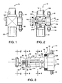
- a washer for a tank 10 has a having a housing 14 with a liquid inlet 16, a piston chamber 20 and a nozzle and crankshaft assembly 24 contained substantially inside the housing 14. Externally, the hub 26 of the nozzle and crankshaft assembly 24 and nozzles 30 can be seen.
- the nozzle and crankshaft assembly 24 is a generally elongated hollow element with an axial opening 26. At one end the nozzle and crankshaft assembly 24 includes the hub 28 of the nozzle assembly which provides a liquid connection between the interior of the housing 14 and the nozzles 30. The nozzle and crankshaft assembly 24 is supported in the housing 14 for rotation about an axis 34.
- nozzle hub support 44 which comprises a hollow section of reduced outer diameter.
- the nozzle hub support 44 bears against the interior surface of O-ring 46 which is supported in the housing 14 while the inner face 48 of nozzle hub support 44 bears against the end wall of O-ring 46 so that a liquid tight relation is maintained between them.
- a further hollow section 54 of reduced outer diameter comprising a front portion 56 and a rear portion 60 which are separated by a cut-out 64.
- the front portion 56 is provided with a plurality of circumferentially space openings 66 (only one of which is shown) to enable liquid which is in the housing 14 to enter the axial opening 26 of the of the nozzle and crankshaft assembly 24.
- the cut-out 64 is of sufficient depth so that it extends substantially entirely through the further hollow section of reduced diameter 54 so that the remnant of the axial opening 26 defines an elongated groove 70.
- ratchet assembly 80 Immediately adjacent the rear portion 60 of the further hollow section of reduced diameter 54 is a ratchet assembly 80 which will be described in detail herein.
- the ratchet assembly 80 includes a hollow cylindrical section 84 whose axial opening is a part of axial opening 26.
- the diameter of hollow cylindrical section 84 is slightly less than the diameter of further hollow section of reduced diameter 54 so that its juncture with further hollow section of reduced diameter 54 forms a bearing surface 86 against which a bevel gear, which will be described in detail, bears when the bevel gear is supported on the outer wall 88 of hollow cylindrical section 84.
- a hollow cylindrical member 96 with external threads 98 is connected to hollow cylindrical section 84.
- the opening in hollow cylindrical section 96 is part of the axial opening 26 in the nozzle and crankshaft assembly 24.
- a torsion rod 108 has one end fixed in the end wall 112 of reduced diameter section 54. Preferably, it resides in the elongated groove 70 formed by the cut-out 64.
- the hollow cylindrical section 84 has a slot 116 in its peripheral wall.
- the interior wall of the hollow cylindrical section 84 includes a longitudinally extending notch 118.
- a pawl 124 which is an elongated generally arcuate member has one end 126 in engagement with the notch 118 and its other end 128 extending through the slot 116 in hollow cylindrical section 84.
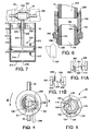
- a bevel gear 130 which was mentioned earlier, is shown in Figure 3 exploded to the left of the of hollow cylindrical section 84 and pawl 124 which support it. As seen in Figure 5 , the interior circumference of the bevel gear 130 is provided with a plurality of teeth 134 which can receive the other end 128 of the pawl 124.
- the bevel gear 130 remains fixed relative to the housing 14 since the pawl 124 yields under the force of the torsion rod 70 to enable it to slip from tooth to tooth 134 on the interior of the bevel gear 130.
- the bevel gear 130 is an important part of the mechanism for enabling the washer 10 to pivot about an axis that is in alignment with the liquid inlet to the housing 14 in a series of discrete steps as will be more fully explained.
- the nozzle and crankshaft assembly 24 is held in the housing 14 by an end cap 146 ( Figure 2 ) which threadingly engages the aforementioned external threads 98 on hollow cylindrical member 96 and which bears against an O-ring which is seated in the housing 14.
- the liquid inlet 16 can best be seen in Figures 2 and 6 . It comprises, in part, a collar 150 with a smooth interior wall which defines a bearing surface 152.
- the collar 150 has a reduced diameter lower section 158 which has external threads to engage complimentary internal threads on an internal collar 166 in the upper portion of the housing 14. Suitable O-rings are provided to reduce the likelihood of liquid leakage between the parts.
- an elongated hollow sleeve 180 Contained within the smooth interior wall and in engagement with the bearing surface 152 in collar 150 is an elongated hollow sleeve 180 which has an upper portion 182 which extends above the collar 150 and which has external threads 184. Its lower portion 190 includes a bevel gear 190 which is in driven relationship with earlier mentioned bevel gear 130 which is seen best in Figures 3 and 6 .
- a second collar 194 has at its lower end internal threads 196 which are complementary to and engage external threads 182. At its upper end, collar 194 has internal threads 200 which can be connected to complementary threads on a liquid supply pipe 204.
- elongated hollow sleeve 180 and bevel gear 190 along with collar 194 are fixed to the liquid supply pipe 204. Accordingly, they are incapable of movement. However, the collar 150 is free to rotate about an axis defined by the liquid supply pipe 204.
- the housing 14 is connected to the collar 150. Accordingly, both the collar 150 and the housing 14 can rotate together about the liquid supply pipe 204.
- the piston chamber 20 may be generally cylindrical. It includes a side wall 210 and a bottom wall 212. Its top wall 214 is defined by the bottom wall of a cylindrical member 216 extending downwardly from the lower part of housing 14 and which has external threads.
- the piston chamber 20 includes internal threads that engage the external threads on the cylindrical member 216 to connect the piston chamber 20 to the housing 14.
- the top wall 214 includes an upwardly extending collar 226 having a central opening 228 surrounded by a bushing 230.
- a first drain opening 234 is provided in the upper portion of the sidewall 210.
- a second drain opening 236 is provided in the bottom wall 212.
- the piston 240 includes a piston head 242 to which is connected an upwardly extending connecting rod 246 which extends through central opening 228.
- the upwardly extending connecting rod 246 includes an open sided rectangular cage 248 at its upper end.
- the bottom wall 250 of the cage 248 includes an opening 256 which connects to an elongated conduit 260 which extends downwardly through the connecting rod 246.
- the lower end of the connecting rod 246 terminates inside the piston head 242.
- the lower end of the connecting rod 246 includes a laterally directed opening 262 which is in liquid connection with the aforementioned elongated conduit 260.
- a guide roller 264 which may a generally hollow cylindrical member is contained within the cage 248 so that it can reciprocate from one end of the cage 248 to the other as seen in Figure 8B .
- the rectangular cage 248 and guide roller 264 are received in and are retained in the cut-out 64 by an elongated pin 268 which extends through an opening in the hub 28 of the nozzle assembly and extends into a blind hole (not shown) in the rear portion 60 of hollow section 54.
- the elongated pin 268 is spaced radially from the axis of rotation of the nozzle and crankshaft 24.
- the length of roller 264 is slightly less than the length of cut-out 64 ( Figure 2 and 3 ).
- the guide roller 264 is constrained in the cut-out 64 so that it can only move back and forth in the rectangular cage 248.
- the piston head 242 includes an upper end cap 270, a mid-portion 272 and a lower end cap 274.
- the upper end cap 270 comprises a relatively flat disc, having a downwardly facing peripheral notch in which is received an O-ring seal 282.
- the upper end cap 270 includes a first opening 286 which lies along one of its diameters but spaced from its center. From the first opening 286 there is connected a downwardly extending conduit 288 having a beveled end 290 with its inner juncture with the conduit 288 being closer to the upper end cap 270 than its outer edge 296.
- a pin 302 having a head 306 whose diameter is greater than the opening 300 and which includes an upwardly extending shaft 308 having a diameter less that the opening 300 is provided.
- the pin 302 is positioned in the opening with the head 304 against the underside of the upper end cap 270 and its shaft 308 extending through the opening 300 so that its distal end 310 is exposed.
- the pin 302 will move downwardly through opening 300.
- An opening 314 is provided near the periphery of the upper end cap 270 through which the lower end of the connecting rod 246 is received.
- Openings 318 are provided in the upper end cap 270 to receive suitable screws for connecting the upper end cap to mid-portion 272.
- the lower end cap 274 is a mirror image of the upper end cap 270. Thus, it need not be described further other than to say that its parts are identified by the same numerals as those associated with the upper end cap 270 except that they are followed by a "'".
- pins 308 and 308' are opposite each other, and conduits 288 and 288' and their respective beveled ends 290 and 290' are opposite each other.
- the mid-portion 272 of the piston head 242 includes a diametrically extending elongated relatively wide opening 330.
- a flat blade 334, preferably made of a thin rust resistant metal 334 is slightly longer than the opening 330 has its ends wedged into notches at the ends of opening 330 so that it is slightly bowed.
- FIG 10A the blade 334 is shown bowed upwardly to create a "frown.” However, upon the application of force, it can be pushed until it snaps into a downwardly bowed position where it achieves a "smile" as seen in Figure 10B .
- the mid-portion 272 includes an opening 336 which can be aligned with openings 314 in the upper end cap 270 and opening 214' in the lower end cap 274 when the piston head 240 is assembled such as when screws passing through 318 and 318' are connected to internally threaded openings 328 in the mid-portion 272.
- the connecting rod 246 is received in openings 314, 336 and 314' in the piston head 242 so that laterally extending opening 262 in the lower end of the connecting rod 246 is aligned with conduit 342 in the mid-portion 272 to permit liquid flowing through laterally extending opening 262 to enter the opening 330 in the mid-portion 272.
- the connecting rod 246 is retained in position by a suitable set screw (not shown) which is threadingly received in opening 356.
- the opening 336 is also connected by another conduit 344 to a recess 348 formed in the circumferential wall 350 of the mid-portion 272.
- a gasket 354 (shown in section) extends around the circumferential wall 350 of the mid-portion 272 to provide further sealing between the piston head 240 and the piston chamber 20.
- the washer 10 is connected to liquid supply pipe 204 by being threadingly connected to collar 194.
- Collar 194 is connected to elongated hollow sleeve 180 and its bevel gear 190 so that the collar 194, hollow sleeve 180 and bevel gear 190 are constrained against movement by the liquid supply pipe 204.
- a suitable liquid such as a cleaning solution or the like enters the washer 10 through the supply pipe 204 and liquid inlet 16 filling the housing 14.
- the liquid is divided into two liquid paths.
- One path includes the axial opening 26 in the nozzle and crankshaft assembly 24 which directs the liquid to the hub 28 of the nozzle assembly and then out the nozzles 30 to be sprayed onto the surface to be cleaned.
- the second liquid path directs about one percent of the liquid entering the washer 10 into the piston chamber 20.
- the second liquid path includes the opening 256 at the bottom of rectangular cage 248, elongated conduit 260 in connecting rod 246, laterally extending opening 262 at the bottom of connecting rod 246 and conduit 342 in the mid-portion 272 of the piston head 240 and into opening 330.
- Liquid initially received in opening 330 is directed to either one side or the other of the piston head 242, depending on the position of the blade 334, to drive the piston in the opposite direction in a manner which will now be described.
- the pin 302' Since the pin 302' is located to the side of the blade 334, it initially forces the part 338 of the blade 334 against which is presses to move so that the blade 334, which is slightly longer than opening assumes the configuration of an "S" as seen in Figure 11A .
- the force which the pin 302' applies to the blade 334 is stored in the "S" configuration as energy.
- the blade 334 is resilient, some of the stored energy is released by forcing the rest 340 of the blade 334 into closer relation to the beveled end 290' thereby further assuring that there is no liquid flow through it.
- the rectangular cage 248 and guide roller 264 are connected to the nozzle and crankshaft assembly 24 by elongated pin 268 ( Figure 7 ).
- the elongated pin 268 is spaced radially from the axis of rotation of the nozzle and crankshaft 24.
- the range of arcuate movement can be reduced to about slightly greater than 60°.
- the guide roller 264 moves move back and forth in the rectangular cage 248 as the nozzle and crankshaft assembly rotates to maintain its driving connection with them.
- the range of movement of the nozzle and crankshaft assembly 24 is limited by the range of movement of the piston head 240 and the length of the connecting rod 246.
- the range of movement of the piston head 240 is limited by the distance between the upper and lower walls 212 and 214 of the piston chamber 20 and/or the length of the pins 302 and 302'. Thus, if the pins are longer, the reversal of movement of the piston head 240 occurs sooner.
- the arc of reciprocation is further controlled by limiting the length of the connecting rod 246 to a distance that is less than the distance between the upper limit of piston 240 movement and the upper part of cut-out 64.
- the speed at which the reciprocation of the piston occurs can be controlled by changing the size of the drain openings 234 and 236.
- larger opening permit the liquid to leave the piston chamber 20 faster to increase the speed of the piston.
- nozzles 30 When two nozzles 30 are used, they reciprocate through an arc of slightly more than 90°. When three nozzles are used, they reciprocate through an arc of slightly more than 60°. However, these arcs are not critical and the cleaner will work equally as well to clean tanks if the arcs were somewhat smaller or somewhat larger.
- the washer 10 is driven about the liquid supply pipe 204 by the reciprocation of the nozzle and crankshaft assembly 24.
- the elongated hollow sleeve 180 and bevel gear 190 are fixed to the liquid supply pipe 204 and thus can not rotate. Since the bevel gear 130 in engagement with bevel gear 190, it also can not rotate.
- the nozzle and crankshaft assembly 24 supports bevel gear 130.
- the nozzle and crankshaft assembly 24 is limited for movement in one direction relative to the bevel gear 130 by the ratchet assembly 80.
- the bevel gear 130 is required to rotate around bevel gear 190 and the supply pipe 204 in a series of "steps."
- the number of steps necessary to rotate the housing 14 and nozzles 130 around the supply pipe 204 to wash the interior of a tank can be varied in accordance with the number of teeth on each of the bevel gears 130 and 190 and the number of teeth 134 in the interior circumference of the bevel gear 130.
- the piston 234 reciprocates inside piston chamber 20 under the force of the liquid entering the washer 10.
- the reciprocation of the piston causes the nozzle and crankshaft assembly 24 to reciprocate through about 90° as liquid is sprayed the nozzle 30.
- the reciprocation of the nozzle and crankshaft assembly 24 causes the bevel gear 130 to move around the bevel gear 190 to cause the housing 14 to rotate around the liquid supply conduit 204 in a plurality of steps to wash the interior of the tank that is being cleaned.
Landscapes
- Engineering & Computer Science (AREA)
- Mechanical Engineering (AREA)
- Reciprocating Pumps (AREA)
- Centrifugal Separators (AREA)
- Cleaning By Liquid Or Steam (AREA)
- Cleaning In General (AREA)
Claims (10)
- Appareil de lavage pour réservoir (10) comportant :un logement (14) ayant une première (20) et une seconde chambres ;une conduite d'entrée de liquide (16, 204) raccordée audit logement pour fournir du liquide audit logement ;une pluralité de buses (30), lesdites buses étant supportées sur ledit logement à des fins de mouvement de va-et-vient autour d'un premier axe (34), et lesdites buses (30) étant en communication liquide avec ladite seconde chambre de sorte que ladite seconde chambre et lesdites buses définissent une conduite liquide ;un piston (240) comprenant une tête de piston (242) dans ladite première chambre (20) montée à des fins de mouvement de va-et-vient dans ledit logement (14) le long d'un second axe ;un ensemble buse et vilebrequin (24) situé dans ladite seconde chambre, dans lequel ledit ensemble buse et vilebrequin (24) est un élément creux allongé, et par ailleurs dans lequel ledit ensemble buse et vilebrequin (24) raccorde ledit piston (240) auxdites buses (30) pour amener lesdites buses (30) à s'animer d'un mouvement de va-et-vient quand ledit piston (240) s'anime d'un mouvement de va-et-vient ; etdes moyens en mesure de se mettre mutuellement en prise (130,190) supportés par ladite conduite d'entrée de liquide (16, 204) et ledit ensemble buse et vilebrequin (24) pour amener ledit logement (14) à se mettre en rotation autour d'un axe de ladite conduite d'entrée de liquide (16, 204), dont l'axe coïncide avec ledit second axe, alors que ledit piston (240) s'anime d'un mouvement de va-et-vient dans ledit logement (14) le long dudit second axe ;lesdits moyens en mesure de se mettre mutuellement en prise comportant un premier engrenage conique (130) supporté sur ledit ensemble buse et vilebrequin (24), et un ensemble d'encliquetage (80) raccordé entre ledit premier engrenage conique (130) et ledit ensemble buse et vilebrequin (24) pour permettre audit premier engrenage conique (130) de se mettre en rotation par rapport audit ensemble buse et vilebrequin (24) dans une direction, et pour permettre audit premier engrenage conique d'être entraîné par ledit ensemble buse et vilebrequin (24) dans une seconde direction.
- Appareil de lavage pour réservoir (10) selon la revendication 1, dans lequel lesdits moyens en mesure de se mettre mutuellement en prise colportent par ailleurs un second engrenage conique (190), ledit second engrenage conique (190) étant fixé à ladite conduite d'entrée de liquide (16, 204), et dans lequel le mouvement de va-et-vient de l'ensemble buse et vilebrequin (24) amène le premier engrenage conique (130) à se déplacer autour dudit second engrenage conique (190) pour amener le logement (14) à se mettre en rotation autour dudit axe de ladite conduite d'entrée de liquide (16, 204).
- Appareil de lavage pour réservoir (10) selon la revendication 1 ou la revendication 2, dans lequel
ledit ensemble d'encliquetage (80) raccordé entre ledit premier engrenage conique (130) et ledit ensemble buse et vilebrequin (24) pour permettre audit premier engrenage conique (130) de se mettre en rotation par rapport audit ensemble buse et vilebrequin (24) dans une direction, et pour permettre audit premier engrenage conique (130) d'être entraîné par ledit ensemble buse et vilebrequin (24) dans une seconde direction comporte
un évidement pour cliquet (118) sur la paroi intérieure dudit ensemble buse et vilebrequin (24),
une ouverture (116) dans ladite paroi dudit ensemble buse et vilebrequin (24) généralement de manière opposée audit évidement pour cliquet (118),
un cliquet (124), une partie dudit cliquet (124) étant reçue dans ledit évidement pour cliquet (118) et une autre partie dudit cliquet (124) s'étendant au travers de ladite ouverture (116) dans ladite paroi, et
un élément de torsion allongé (108) raccordé entre ledit ensemble buse et vilebrequin (24) et ledit cliquet (124) afin de solliciter ladite autre partie dudit cliquet (124) à se mettre en prise avec ledit premier engrenage conique (130). - Appareil de lavage pour réservoir (10) selon la revendication 3, dans lequel une extrémité dudit élément de torsion allongé (108) est raccordée audit ensemble buse et vilebrequin (24), et l'autre extrémité dudit élément de torsion allongé (108) est raccordée audit cliquet (124).
- Appareil de lavage pour réservoir (10) selon l'une quelconque des revendications précédentes, dans lequel ladite tête de piston (242) comprend :une entrée de liquide (262) et deux sorties de liquide (288, 288') ; etun moyen permettant de diriger le liquide entrant dans ladite tête de piston (242) au travers de ladite tête de piston par alternance au travers desdites sorties de liquide (288, 288') pour amener ledit piston (240) à s'animer d'un mouvement de va-et-vient dans ladite première chambre (20).
- Appareil de lavage pour réservoir (10) selon la revendication 5, dans lequel chacune desdites sorties de liquide (288, 288') est sur un côté différent de ladite tête de piston (242).
- Appareil de lavage pour réservoir (10) selon la revendication 5 ou la revendication 6, dans lequel ledit moyen permettant de diriger le liquide comporte un moyen permettant de fermer lesdites sorties de liquide (288, 288') dans ladite tête de piston (242),
ledit moyen permettant de fermer lesdites sorties de liquide (288, 288') sert à fermer de manière sélective lesdites sorties de liquide (288, 288') de telle manière que, lorsque l'une desdites sorties de liquide (288, 288') est fermée l'autre sortie de liquide (288, 288') est ouverte. - Appareil de lavage pour réservoir (10) selon l'une quelconque des revendications 5 à 7, dans lequel
ladite tête de piston (242) comprend une partie à mi-chemin (272) et des embouts supérieur et inférieur (270, 274), ladite partie à mi-chemin (272) comprenant une ouverture centrale (330), ladite ouverture centrale (330) étant en communication liquide avec les deux desdites sorties de liquide (288, 288'),
chacune desdites sorties de liquide (288, 288') étant dans l'un desdits embouts de piston (270, 274), et
un moyen dans ladite ouverture centrale (330) permettant de fermer de manière sélective lesdites sorties de liquide (288, 288') de telle manière que, lorsque l'une desdites sorties de liquide (288, 288') est fermée l'autre sortie de liquide (288, 288') est ouverte. - Appareil de lavage pour réservoir (10) selon la revendication 8, dans lequel
ledit moyen permettant de fermer de manière sélective lesdites sorties de liquide (288, 288') comporte un élément flexible élastique (334) supporté dans ladite ouverture centrale (330) dans ladite partie à mi-chemin (272), ledit élément flexible élastique (334) étant mobile entre une première position où l'une desdites sorties de liquide (288, 288') est fermée et une seconde position où l'autre sortie de liquide (288, 288') est fermée. - Appareil de lavage pour réservoir (10) selon la revendication 9, comprenant
un moyen permettant de déplacer ledit élément flexible élastique (334) vers l'une desdites positions depuis l'autre position,
ledit moyen nommé en dernier servant à stocker de l'énergie dans ledit élément flexible élastique (334) quand ledit moyen nommé en dernier se déplace vers ladite autre position,
ledit moyen permettant de déplacer ledit élément flexible élastique comportant des goupilles (302, 302') s'étendant au travers desdits embouts (270, 274) et étant en mesure de se mettre mutuellement en prise avec les parois d'extrémité de ladite première chambre (20) et ledit élément flexible élastique (334) de telle manière que, lorsque ledit piston (240) s'anime d'un mouvement de va-et-vient dans ladite première chambre (20), le mouvement de celui-ci actionne lesdites goupilles (302, 302') pour mettre en prise par alternance les parois d'extrémité de ladite première chambre (20) et ledit élément flexible élastique (334), et pour déplacer une partie (338) dudit élément flexible élastique (334) vers ladite autre position.
Applications Claiming Priority (3)
| Application Number | Priority Date | Filing Date | Title |
|---|---|---|---|
| US34728702P | 2002-01-09 | 2002-01-09 | |
| US347287P | 2002-01-09 | ||
| PCT/US2003/000653 WO2003059541A1 (fr) | 2002-01-09 | 2003-01-09 | Appareil de lavage pour reservoirs |
Publications (3)
| Publication Number | Publication Date |
|---|---|
| EP1472020A1 EP1472020A1 (fr) | 2004-11-03 |
| EP1472020A4 EP1472020A4 (fr) | 2005-10-26 |
| EP1472020B1 true EP1472020B1 (fr) | 2012-03-21 |
Family
ID=23363097
Family Applications (1)
| Application Number | Title | Priority Date | Filing Date |
|---|---|---|---|
| EP03729614A Expired - Lifetime EP1472020B1 (fr) | 2002-01-09 | 2003-01-09 | Appareil de lavage pour reservoirs |
Country Status (5)
| Country | Link |
|---|---|
| US (1) | US7686893B2 (fr) |
| EP (1) | EP1472020B1 (fr) |
| AT (1) | ATE550109T1 (fr) |
| AU (1) | AU2003210475A1 (fr) |
| WO (1) | WO2003059541A1 (fr) |
Families Citing this family (6)
| Publication number | Priority date | Publication date | Assignee | Title |
|---|---|---|---|---|
| US8382915B2 (en) * | 2005-06-22 | 2013-02-26 | Nlb Corp. | Concrete mixer drum cleaner |
| US20080047587A1 (en) * | 2006-08-22 | 2008-02-28 | Ball David M | Method and apparatus for cleaning tanks and other containers |
| SE534731C2 (sv) * | 2009-04-09 | 2011-12-06 | Scanjet Marine Ab | Spolanordning för rengöring av insidorna på ett slutet område |
| SE534034C2 (sv) * | 2009-06-08 | 2011-04-05 | Scanjet Marine Ab | Anordning för rengöring av slutna utrymmen |
| US10550317B2 (en) * | 2015-08-26 | 2020-02-04 | Halliburton Energy Services, Inc. | Sugar based epoxy resins with enhanced properties for sand consolidation in subterranean formations |
| CN112495977A (zh) * | 2020-11-09 | 2021-03-16 | 广西玉柴机器股份有限公司 | 活塞连杆工装篮 |
Family Cites Families (13)
| Publication number | Priority date | Publication date | Assignee | Title |
|---|---|---|---|---|
| US2784034A (en) * | 1955-05-20 | 1957-03-05 | Maurice E Metcalf | Tank cleaning machine |
| US3696825A (en) * | 1969-05-19 | 1972-10-10 | John E Guignon | Tank washer |
| US4056227A (en) * | 1975-12-18 | 1977-11-01 | Olav Hakon Fismen | Apparatus for cleaning tanks and the like |
| US4214705A (en) * | 1978-12-18 | 1980-07-29 | Chemdet Sonic Systems, Inc. | Apparatus for cleaning tanks |
| GB8420532D0 (en) * | 1984-08-13 | 1984-09-19 | Robinson M | Tank washers |
| US4635830A (en) * | 1984-11-29 | 1987-01-13 | The United States Of America As Represented By The Secretary Of Agriculture | Portable, self-powered, adjustable herbicide dispensing system |
| US4779797A (en) * | 1987-12-21 | 1988-10-25 | Breconcherry Steel Limited | Tankwasher |
| GB8903775D0 (en) * | 1989-02-20 | 1989-04-05 | Breconcherry Steel | Tankwasher |
| GB2262316B (en) * | 1991-12-05 | 1995-03-29 | Breconcherry Ltd | A piston and cylinder arrangement with its own control valve mechanism |
| WO1996037315A1 (fr) * | 1995-05-23 | 1996-11-28 | Michael Robinson | Dispositif permettant de nettoyer l'interieur d'un recipient |
| US5720310A (en) * | 1996-08-01 | 1998-02-24 | Moulder; Jeffrey Ernest | Tank car cleaning and rinsing apparatus and method |
| AU2001243313A1 (en) * | 2000-02-29 | 2001-09-12 | Bombardier Inc. | Four stroke engine with cooling system |
| GB2372951A (en) * | 2001-03-09 | 2002-09-11 | Breconcherry Ltd | Device for spraying a surface with unequal flow distribution |
-
2003
- 2003-01-09 AU AU2003210475A patent/AU2003210475A1/en not_active Abandoned
- 2003-01-09 US US10/499,386 patent/US7686893B2/en not_active Expired - Fee Related
- 2003-01-09 WO PCT/US2003/000653 patent/WO2003059541A1/fr not_active Ceased
- 2003-01-09 EP EP03729614A patent/EP1472020B1/fr not_active Expired - Lifetime
- 2003-01-09 AT AT03729614T patent/ATE550109T1/de active
Also Published As
| Publication number | Publication date |
|---|---|
| US7686893B2 (en) | 2010-03-30 |
| EP1472020A1 (fr) | 2004-11-03 |
| ATE550109T1 (de) | 2012-04-15 |
| EP1472020A4 (fr) | 2005-10-26 |
| AU2003210475A1 (en) | 2003-07-30 |
| WO2003059541A1 (fr) | 2003-07-24 |
| US20050005955A1 (en) | 2005-01-13 |
Similar Documents
| Publication | Publication Date | Title |
|---|---|---|
| CN112956976B (zh) | 维护基站及清洁机器维护系统 | |
| CN203018246U (zh) | 涂料喷涂器 | |
| US3275247A (en) | Controllable jet nozzle pipe cleaning device | |
| US3696825A (en) | Tank washer | |
| KR100386898B1 (ko) | 세척장치 | |
| US3595256A (en) | Vessel-cleaning apparatus | |
| WO2003051762A2 (fr) | Robinet de distribution pour une source sous pression | |
| CN116528989B (zh) | 可缩回清洁设备和系统 | |
| US7686893B2 (en) | Washer for tanks | |
| JP2025168609A (ja) | デュアルタンク口腔洗浄器 | |
| EP0384690B1 (fr) | Dispositif de nettoyage pour des conteneurs | |
| US3625425A (en) | Tank washers | |
| EP0409305B1 (fr) | Dispositif de nettoyage des conduites de bière, avec dispositif de couplage pour celui-ci | |
| CN114992354B (zh) | 一种便于清洁球阀及其使用方法 | |
| CN114585446B (zh) | 就地清洁机器人喷嘴系统 | |
| CN223385897U (zh) | 柱塞式灌装阀及灌装装置 | |
| GB1592733A (en) | Pipeline valves | |
| US20240198391A1 (en) | Cleaning Device | |
| CN116393923B (zh) | 一种球阀的加工工艺及球阀 | |
| CN111346885B (zh) | 一种tdd喷淋阀 | |
| JPH04215881A (ja) | 洗浄ノズル | |
| JPH1018977A (ja) | 無発塵送液装置 | |
| CN210784778U (zh) | 一种冲洗装置的管路结构 | |
| CN118007763A (zh) | 一种马桶自洁装置及马桶 | |
| SU1260000A1 (ru) | Устройство дл очистки поверхности |
Legal Events
| Date | Code | Title | Description |
|---|---|---|---|
| PUAI | Public reference made under article 153(3) epc to a published international application that has entered the european phase |
Free format text: ORIGINAL CODE: 0009012 |
|
| 17P | Request for examination filed |
Effective date: 20040617 |
|
| AK | Designated contracting states |
Kind code of ref document: A1 Designated state(s): AT BE BG CH CY CZ DE DK EE ES FI FR GB GR HU IE IT LI LU MC NL PT SE SI SK TR |
|
| AX | Request for extension of the european patent |
Extension state: AL LT LV MK RO |
|
| A4 | Supplementary search report drawn up and despatched |
Effective date: 20050912 |
|
| 17Q | First examination report despatched |
Effective date: 20080213 |
|
| GRAP | Despatch of communication of intention to grant a patent |
Free format text: ORIGINAL CODE: EPIDOSNIGR1 |
|
| GRAS | Grant fee paid |
Free format text: ORIGINAL CODE: EPIDOSNIGR3 |
|
| GRAA | (expected) grant |
Free format text: ORIGINAL CODE: 0009210 |
|
| AK | Designated contracting states |
Kind code of ref document: B1 Designated state(s): AT BE BG CH CY CZ DE DK EE ES FI FR GB GR HU IE IT LI LU MC NL PT SE SI SK TR |
|
| REG | Reference to a national code |
Ref country code: GB Ref legal event code: FG4D |
|
| REG | Reference to a national code |
Ref country code: CH Ref legal event code: EP |
|
| REG | Reference to a national code |
Ref country code: IE Ref legal event code: FG4D |
|
| REG | Reference to a national code |
Ref country code: AT Ref legal event code: REF Ref document number: 550109 Country of ref document: AT Kind code of ref document: T Effective date: 20120415 |
|
| REG | Reference to a national code |
Ref country code: DE Ref legal event code: R096 Ref document number: 60340338 Country of ref document: DE Effective date: 20120510 |
|
| REG | Reference to a national code |
Ref country code: NL Ref legal event code: VDEP Effective date: 20120321 |
|
| PG25 | Lapsed in a contracting state [announced via postgrant information from national office to epo] |
Ref country code: GR Free format text: LAPSE BECAUSE OF FAILURE TO SUBMIT A TRANSLATION OF THE DESCRIPTION OR TO PAY THE FEE WITHIN THE PRESCRIBED TIME-LIMIT Effective date: 20120622 Ref country code: FI Free format text: LAPSE BECAUSE OF FAILURE TO SUBMIT A TRANSLATION OF THE DESCRIPTION OR TO PAY THE FEE WITHIN THE PRESCRIBED TIME-LIMIT Effective date: 20120321 |
|
| REG | Reference to a national code |
Ref country code: AT Ref legal event code: MK05 Ref document number: 550109 Country of ref document: AT Kind code of ref document: T Effective date: 20120321 |
|
| PG25 | Lapsed in a contracting state [announced via postgrant information from national office to epo] |
Ref country code: CY Free format text: LAPSE BECAUSE OF FAILURE TO SUBMIT A TRANSLATION OF THE DESCRIPTION OR TO PAY THE FEE WITHIN THE PRESCRIBED TIME-LIMIT Effective date: 20120321 |
|
| PG25 | Lapsed in a contracting state [announced via postgrant information from national office to epo] |
Ref country code: CZ Free format text: LAPSE BECAUSE OF FAILURE TO SUBMIT A TRANSLATION OF THE DESCRIPTION OR TO PAY THE FEE WITHIN THE PRESCRIBED TIME-LIMIT Effective date: 20120321 Ref country code: SE Free format text: LAPSE BECAUSE OF FAILURE TO SUBMIT A TRANSLATION OF THE DESCRIPTION OR TO PAY THE FEE WITHIN THE PRESCRIBED TIME-LIMIT Effective date: 20120321 Ref country code: EE Free format text: LAPSE BECAUSE OF FAILURE TO SUBMIT A TRANSLATION OF THE DESCRIPTION OR TO PAY THE FEE WITHIN THE PRESCRIBED TIME-LIMIT Effective date: 20120321 Ref country code: BE Free format text: LAPSE BECAUSE OF FAILURE TO SUBMIT A TRANSLATION OF THE DESCRIPTION OR TO PAY THE FEE WITHIN THE PRESCRIBED TIME-LIMIT Effective date: 20120321 Ref country code: SI Free format text: LAPSE BECAUSE OF FAILURE TO SUBMIT A TRANSLATION OF THE DESCRIPTION OR TO PAY THE FEE WITHIN THE PRESCRIBED TIME-LIMIT Effective date: 20120321 |
|
| PG25 | Lapsed in a contracting state [announced via postgrant information from national office to epo] |
Ref country code: SK Free format text: LAPSE BECAUSE OF FAILURE TO SUBMIT A TRANSLATION OF THE DESCRIPTION OR TO PAY THE FEE WITHIN THE PRESCRIBED TIME-LIMIT Effective date: 20120321 Ref country code: PT Free format text: LAPSE BECAUSE OF FAILURE TO SUBMIT A TRANSLATION OF THE DESCRIPTION OR TO PAY THE FEE WITHIN THE PRESCRIBED TIME-LIMIT Effective date: 20120723 |
|
| PLBE | No opposition filed within time limit |
Free format text: ORIGINAL CODE: 0009261 |
|
| STAA | Information on the status of an ep patent application or granted ep patent |
Free format text: STATUS: NO OPPOSITION FILED WITHIN TIME LIMIT |
|
| PG25 | Lapsed in a contracting state [announced via postgrant information from national office to epo] |
Ref country code: NL Free format text: LAPSE BECAUSE OF FAILURE TO SUBMIT A TRANSLATION OF THE DESCRIPTION OR TO PAY THE FEE WITHIN THE PRESCRIBED TIME-LIMIT Effective date: 20120321 Ref country code: DK Free format text: LAPSE BECAUSE OF FAILURE TO SUBMIT A TRANSLATION OF THE DESCRIPTION OR TO PAY THE FEE WITHIN THE PRESCRIBED TIME-LIMIT Effective date: 20120321 Ref country code: AT Free format text: LAPSE BECAUSE OF FAILURE TO SUBMIT A TRANSLATION OF THE DESCRIPTION OR TO PAY THE FEE WITHIN THE PRESCRIBED TIME-LIMIT Effective date: 20120321 |
|
| 26N | No opposition filed |
Effective date: 20130102 |
|
| REG | Reference to a national code |
Ref country code: DE Ref legal event code: R097 Ref document number: 60340338 Country of ref document: DE Effective date: 20130102 |
|
| PG25 | Lapsed in a contracting state [announced via postgrant information from national office to epo] |
Ref country code: ES Free format text: LAPSE BECAUSE OF FAILURE TO SUBMIT A TRANSLATION OF THE DESCRIPTION OR TO PAY THE FEE WITHIN THE PRESCRIBED TIME-LIMIT Effective date: 20120702 |
|
| PG25 | Lapsed in a contracting state [announced via postgrant information from national office to epo] |
Ref country code: BG Free format text: LAPSE BECAUSE OF FAILURE TO SUBMIT A TRANSLATION OF THE DESCRIPTION OR TO PAY THE FEE WITHIN THE PRESCRIBED TIME-LIMIT Effective date: 20120621 |
|
| PG25 | Lapsed in a contracting state [announced via postgrant information from national office to epo] |
Ref country code: MC Free format text: LAPSE BECAUSE OF NON-PAYMENT OF DUE FEES Effective date: 20130131 |
|
| REG | Reference to a national code |
Ref country code: CH Ref legal event code: PL |
|
| REG | Reference to a national code |
Ref country code: IE Ref legal event code: MM4A |
|
| PG25 | Lapsed in a contracting state [announced via postgrant information from national office to epo] |
Ref country code: LI Free format text: LAPSE BECAUSE OF NON-PAYMENT OF DUE FEES Effective date: 20130131 Ref country code: CH Free format text: LAPSE BECAUSE OF NON-PAYMENT OF DUE FEES Effective date: 20130131 |
|
| PG25 | Lapsed in a contracting state [announced via postgrant information from national office to epo] |
Ref country code: IE Free format text: LAPSE BECAUSE OF NON-PAYMENT OF DUE FEES Effective date: 20130109 |
|
| PGFP | Annual fee paid to national office [announced via postgrant information from national office to epo] |
Ref country code: DE Payment date: 20131231 Year of fee payment: 12 |
|
| PGFP | Annual fee paid to national office [announced via postgrant information from national office to epo] |
Ref country code: IT Payment date: 20140108 Year of fee payment: 12 Ref country code: FR Payment date: 20140108 Year of fee payment: 12 |
|
| PGFP | Annual fee paid to national office [announced via postgrant information from national office to epo] |
Ref country code: GB Payment date: 20140108 Year of fee payment: 12 |
|
| PG25 | Lapsed in a contracting state [announced via postgrant information from national office to epo] |
Ref country code: TR Free format text: LAPSE BECAUSE OF FAILURE TO SUBMIT A TRANSLATION OF THE DESCRIPTION OR TO PAY THE FEE WITHIN THE PRESCRIBED TIME-LIMIT Effective date: 20120321 |
|
| PG25 | Lapsed in a contracting state [announced via postgrant information from national office to epo] |
Ref country code: LU Free format text: LAPSE BECAUSE OF NON-PAYMENT OF DUE FEES Effective date: 20130109 Ref country code: HU Free format text: LAPSE BECAUSE OF FAILURE TO SUBMIT A TRANSLATION OF THE DESCRIPTION OR TO PAY THE FEE WITHIN THE PRESCRIBED TIME-LIMIT; INVALID AB INITIO Effective date: 20030109 |
|
| REG | Reference to a national code |
Ref country code: DE Ref legal event code: R119 Ref document number: 60340338 Country of ref document: DE |
|
| GBPC | Gb: european patent ceased through non-payment of renewal fee |
Effective date: 20150109 |
|
| PG25 | Lapsed in a contracting state [announced via postgrant information from national office to epo] |
Ref country code: GB Free format text: LAPSE BECAUSE OF NON-PAYMENT OF DUE FEES Effective date: 20150109 Ref country code: DE Free format text: LAPSE BECAUSE OF NON-PAYMENT OF DUE FEES Effective date: 20150801 |
|
| REG | Reference to a national code |
Ref country code: FR Ref legal event code: ST Effective date: 20150930 |
|
| PG25 | Lapsed in a contracting state [announced via postgrant information from national office to epo] |
Ref country code: FR Free format text: LAPSE BECAUSE OF NON-PAYMENT OF DUE FEES Effective date: 20150202 |
|
| PG25 | Lapsed in a contracting state [announced via postgrant information from national office to epo] |
Ref country code: IT Free format text: LAPSE BECAUSE OF NON-PAYMENT OF DUE FEES Effective date: 20150109 |