EP1473014A1 - Ventouse de liposuccion a jeter - Google Patents
Ventouse de liposuccion a jeter Download PDFInfo
- Publication number
- EP1473014A1 EP1473014A1 EP02788736A EP02788736A EP1473014A1 EP 1473014 A1 EP1473014 A1 EP 1473014A1 EP 02788736 A EP02788736 A EP 02788736A EP 02788736 A EP02788736 A EP 02788736A EP 1473014 A1 EP1473014 A1 EP 1473014A1
- Authority
- EP
- European Patent Office
- Prior art keywords
- cup
- suction cup
- slimming
- projection
- disposable
- Prior art date
- Legal status (The legal status is an assumption and is not a legal conclusion. Google has not performed a legal analysis and makes no representation as to the accuracy of the status listed.)
- Withdrawn
Links
Images



Classifications
-
- A—HUMAN NECESSITIES
- A61—MEDICAL OR VETERINARY SCIENCE; HYGIENE
- A61H—PHYSICAL THERAPY APPARATUS, e.g. DEVICES FOR LOCATING OR STIMULATING REFLEX POINTS IN THE BODY; ARTIFICIAL RESPIRATION; MASSAGE; BATHING DEVICES FOR SPECIAL THERAPEUTIC OR HYGIENIC PURPOSES OR SPECIFIC PARTS OF THE BODY
- A61H9/00—Pneumatic or hydraulic massage
- A61H9/005—Pneumatic massage
-
- A—HUMAN NECESSITIES
- A61—MEDICAL OR VETERINARY SCIENCE; HYGIENE
- A61H—PHYSICAL THERAPY APPARATUS, e.g. DEVICES FOR LOCATING OR STIMULATING REFLEX POINTS IN THE BODY; ARTIFICIAL RESPIRATION; MASSAGE; BATHING DEVICES FOR SPECIAL THERAPEUTIC OR HYGIENIC PURPOSES OR SPECIFIC PARTS OF THE BODY
- A61H9/00—Pneumatic or hydraulic massage
- A61H9/005—Pneumatic massage
- A61H2009/0064—Pneumatic massage suction by releasing a flexible cup after deformation, i.e. without further vacuum source
Definitions
- the present invention relates to a suction cup for slimming to reduce subcutaneous fat in a part of the body to be slimmed down, or to remove congestion in an affected part, and particularly relates to a disposable suction cup for slimming.
- a cupping treatment method for removing congestion comprising the following steps. First, an opening of a suction cup called a sucker or a cupping glass is closely applied to an affected part. Then, the congestion inside the affected part is led to the surface by suctioning the affected area by depressurizing the interior of said cup.
- the depressurizing of the interior of the cup may be accomplished by a suction pump or the like, or by burning alcohol or the like in the cup.
- the congestion in the affected part is removed by the excretory process of blood vessels in the superficial part.
- a beauty regimen for slimming has been proposed utilizing the cupping treatment method.
- the opening of the cup is closely applied to a part of the body having a large amount of subcutaneous fat.
- the excess subcutaneous fat is dissipated and lost by suctioning the part of the body to be slimmed down.
- a method with as much effect as possible is always desired for a beauty regimen for slimming, or for removing congestion in an affected part.
- a more effective method is also desired for such cases in which the cupping treatment is applied to a beauty regimen for slimming or to the treatment of an affected area.
- an object of the present invention to provide an inexpensive disposable suction cup for slimming, in which the depressurized state can be easily relieved after use.
- Another object of the present invention is to provide a disposable suction cup for slimming with which a better slimming effect can be expected.
- a suction cup for slimming of the present invention comprises: an opening end to be closely applied to a part of the body to be slimmed down; and is constructed so that a part of the body to be slimmed down is suctioned by the depressurization of the interior of the suction cup; wherein a portion of the surface of the suction cup is broken by a bending operation after suction, thereby relieving the depressurization of the interior thereof, and enabling removal of the suction cup from the part of the body to be slimmed down.
- Said portion to be broken may comprise: a projection formed on the outer surface of a suction cup; and a thin-walled portion which is formed in the suction cup near the base of the projection, to be broken by bending the projection.
- the suction cup for slimming may include a deforming part which is deformed and flattened by depressurization, as well as a pressing part for pressing a part of the body to be slimmed down that is suctioned into the suction cup when the suction cup is deformed, provided at the inner surface thereof.
- said deforming part may be constructed to be the pressing part, which is deformed inward when the pressure is reduced.
- the deformed part may press the part of the body to be slimmed down that is suctioned into the suction cup.
- the pressing part can also be a projection that is formed on the inner surface of the suction cup.
- a part to be broken is provided on the outer surface of the suction cup.
- This part to be broken is constructed so that the depressurization of the interior of the suction cup can be relieved by breaking the part to be broken by bending, after suctioning.
- the suction cup can be removed from a part of the body to be slimmed down. Therefore a disposable suction cup for slimming is provided, which can be easily relieved of its depressurization, be directly disposed of and in addition, is inexpensive.
- said part to be broken comprises a projection formed on the outer surface of the suction cup and the thin-walled part of the cup which is to be broken by bending the projection
- the operation to relieve depressurization can be performed extremely easily because the air pressures inside and outside the cup can be evened out simply by bending the projection.
- the disposable suction cup for slimming can be inexpensive because it does not have a complicated system to relieve depressurization.
- a suction cup for slimming has a deforming part which is to be deformed and flattened by depressurization as well as a pressing part inside it to press a part of the body to be slimmed down that is suctioned into it when it is deformed, excess subcutaneous fat in a part of the body to be slimmed down can be dissipated and effectively removed.
- the structure of the cup can be simplified because there is no need to make an additional pressing part.
- the pressing part is a projection that is formed on the inner surface of the suction cup
- excess subcutaneous fat in a part of the body to be slimmed down can be dissipated and lost, and congestion in an affected part can be removed more effectively, by pressing the projection against a part of the body to be slimmed down.
- FIG. 1 is a longitudinal sectional view which shows the first embodiment of the disposable suction cup for slimming (in the following simply referred to as "cup") of the present invention.
- This cup 1 is made of resin, and has a bell-shaped, comparatively hard cup main body 3 with a round opening 2 at the bottom.
- the cup main body 3 has a cylindrical body 4 and a spherical top 6 which closes the upper part of the body 4.
- a flange 10 to be applied to a portion of the body to be slimmed down 8 to dissipate subcutaneous fat, is formed in the periphery of the opening 2 of the cup 1.
- a suction aperture 12, for depressurizing the interior of the cup 1 is formed through the pipe 14.
- a check valve 16 is formed in this suction aperture 12 so that air does not flow back into the depressurized interior of the cup 1.
- the depressurized state inside the cup main body 3 is maintained by the check valve 16, even if connecting devices such as a hose is removed from the pipe 14 after the interior 42 of the cup main body 3 is depressurized with a suction pump (not shown in the figure). Therefore, it is possible to place one cup 1 on each of a plurality of parts of the body to be slimmed down 8, and to depressurize and set up these cups 1, connecting and releasing in turn hoses connected to a single suction pump.
- the detailed structure of the check valve 16 will be described later.
- a projection (the part to be broken) 24 protrudes from the top 6, formed integrally therewith.
- This projection 24 is provided to relieve depressurization by bending it and breaking the thin-walled part (the part to be broken) 35 of the top 6.
- the detailed structure of the projection 24 and the thin walled part 35 will be described later.
- Figure 2A, Figure 2B, and Figure 2C show partial cross sections of the top 6 showing the check valve 16, wherein Figure 2A displays the check valve 16 shown in Figure 1, Figure 2B displays the check valve of an alternate construction, and Figure 2C displays the check valve of another alternate construction, respectively.
- a partition 26 with an eyelet 12a is formed inside the pipe 14.
- a discoid valve element 16a is mounted above this partition 26.
- valve element 16a One end of this valve element 16a is fixed to the partition 26, and it can move as shown by the arrow 28 between a closed position, in which it is flush against the partition 26, thereby shutting off the eyelet 12a when the pressure is reduced, and an open position, in which the interior air can pass through to the exterior as shown in Figure 2A during suction. Threads 32 are formed at the tip of the pipe 14, and a rim 30 is screwed onto these threads 32 to protect the valve element 16a.
- a tube or a hose that is not shown in the figure is usually fixed to the periphery of the pipe 14, and it is constructed to be connected to a suction instrument to depressurize the air of the interior 42 of the cup 1. The detailed description of this construction is abbreviated because any known method can be applied to it.
- valve element 17a is discoid like in Figure 2A but it is placed to move freely between the partition 26 and the rim 30.
- This valve element 17a floats when the air of the interior 42 is suctioned, and the airway is secured as shown in Figure 2B by the arrow 19.
- suctioning is stopped and the hose is pulled out, the valve element 17a becomes flush against the partition 26 because the interior 42 is depressurized, and maintains the depressurized state of the interior 42.
- a conical projection 31 with an outwardly facing concave part 33 is formed integrally with the top 6.
- the interior of the concave part 33 has annular tiers 33a and 33b, and communicates with an aperture 37.
- An annular groove 39 is formed in the periphery of the tier 33b.
- a discoid valve element 41 made of a comparatively flexible sponge resin is placed on the tier 33b.
- a discoid lid 45 having an aperture 43 is press fit into an inner wall surface 33c of the concave part 33, and fixed on the tier 33a.
- the valve element 41 moves slightly upward to secure an airway as shown by the arrow 46.
- the valve element 41 is pressed against the tier 33b, and the depressurized state of the interior 42 is maintained.
- Figure 3A is a partial cross section of the top 6 with the projection 24 shown in Figure 1.
- Figure 3B is the partial cross section of the top 6 that shows an alternate construction.
- a round concave part 34 is formed on the rear surface corresponding to the base of the projection 24.
- the thickness of the top 6 at the bottom is thinner because of that the concave part 34. For that reason, when the projection 24 is pushed down to the lateral direction, the thin-walled part 35 is broken, to make an aperture in the top 6, and the air pressures of the interior and the outside of the cup 1 are evened out.
- FIG. 3B shows the concave part 36 displaced from the projection 24.
- the thin-walled part 40 will be broken when the projection 24 is pressed in the direction of the arrow 38.
- the concave parts 34 and 36 in said embodiments are circular concave parts; however, the concave parts may be of any other form, including squares and rectangles.
- FIG 4 is a front view of a cup 50 of the second embodiment.
- Figure 5 is a side view of the cup 50 of Figure 4; and
- Figure 6 shows the bottom plan view of the cup 50 of Figure 4, respectively. Note that the same parts as those shown in Figure 1 are denoted with the same reference numbers in the description.
- the cup 50 has a bell-shaped main body 53, in the same manner as the cup 1 of the first embodiment described above.
- An opening end 55 at the bottom, a check valve16 on the top 56, and a protruded part or a projection 24 are also formed similarly to the first embodiment described above.
- the main body 53 is formed with a thinner material as a whole than the main body 3 shown in Figure 1, and that short grooves 58 are formed in the interior surface of the main body 53 at the front and back thereof, extending from the opening end 55 upward. When viewed from the bottom, the grooves 58 are located to be opposed across the center of the cup 50, as shown in Figure 6.
- Figure 7 shows the cup 50 constructed in this manner in use.
- Figure 7 is the perspective illustration which shows the cup 50 of Figure 4 in use.
- the left and the right parts of the grooves 58 dent by receiving force by the air pressure as shown by arrows 60.
- the part of the body to be slimmed down 8 that is suctioned is pressed from both sides because of the denting of the main body 53, and subcutaneous fat can be effectively dissipated.
- the cup 50 can be easily removed by relieving depressurization by bending the projection 24.
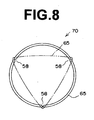
- Figure 8 shows a bottom plan view of a cup 70 of an alternate construction, in which the grooves 58 are formed in three places.
- the opening end 65 is flattened inward roughly in the shape of a triangle as shown by broken lines, because the grooves 58 are provided in three places. Because of this flattening, the part of the body to be slimmed down 8 is pressed from three directions, and the slimming effect is further enhanced.
- FIG. 9 is a cross sectional view of a cup 80 with a deforming part 25. Note that the same parts as those of the cup 1 shown in Figure 1 are denoted with the same reference numbers in the description.
- deforming parts 25 that are deformed at the time of depressurization are formed in a plurality of circumferential locations in the body 4.
- Each deforming part 25 comprises a concave part 20 and a thin-walled part 18 formed by this concave part 20.
- the cup 80 flattens at the thin-walled parts 18 when pressure is reduced.
- the thin-walled parts 18 are made thin by forming said concave parts 20 in the exterior surface of the body 4, toward the interior thereof.
- a groove 22, which makes the thin-walled parts 18 thinner to facilitate deformation thereof, is formed in the circumferential direction of the body 4.
- the groove 22 also serves to define the position at which the thin walled portions 18 protrude during deformation thereof.
- Figure 10 is a cross sectional view which shows the cup 80 of Figure 9 in use. Note that a tube or a hose to be connected to the pipe 14 when it is suctioned and the method (instrument) for suctioning are omitted in Figure 10. As the interior 42 of the cup 80 is depressurized, the thin-walled parts 18 of the deforming parts 25 fold at the part of the groove 22 to be deformed inward, and become pressing parts 44 which protrude into the interior 42.
- the part of the body to be slimmed down 8 that is being suctioned into the cup 80 due to the depressurization is pressed from the lateral direction by said pressing parts 44. Because of this pressing, excess subcutaneous fat in the part of the body to be slimmed down 8 can be effectively dissipated and lost.
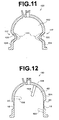
- Figure 11 is a cross sectional view similar to Figure 1 of a cup 100 with concave parts 120 different from the embodiment shown in Figure 9.
- the concave parts 120 or deforming parts, have substantially the same thickness as the body 104 of the cup 100. However, the concave parts 120 are dented into the cup 100, that is, toward the interior 142.
- the concave parts 120 are provided in a plurality of the locations along the circumference of the cup 100.
- the concave parts 120 are flattened by the depressurization of the interior 142, and then protrude inward to become pressing parts 144 indicated by the broken lines.
- the pressing parts 144 press the part of the body to be slimmed down 8 to exhibit a slimming effect similar to that exhibited by the first embodiment.
- Figure 12 displays a cross section of a cup 150 of the fifth embodiment
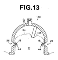
- Figure 13 shows a cross section of the cup 150 in use, similar to Figure 10, respectively.
- the parts having the same construction as Figure 9 are described using the same reference numbers.
- a protrusion (projection) 153 which is to be a pressing part to press the part of the body to be slimmed down 8 when it is suctioned is provided in the interior 42 of the cup.
- the protrusion 153 is made at the top 156.
- the location of the protrusion 153 is not limited to the top 156.
- a protrusion denoted by reference number 158 may be provided in the upper part of the body 154, or a protrusion denoted by reference number 160 may be provided in the lower part of the body 154, as indicated by the broken lines.
- the cup 150 of the fifth embodiment in use will be described with reference to Figure 13.
- the lateral sides of the part of the body to be slimmed down 8 is pressed by the pressing parts 44 which are formed by the deformation of the deforming parts 25.
- an upper side 8a of the part of the body to be slimmed down 8 is pressed by the protrusion 153.
- the shapes of the concave parts 20 and 120 can be made with a slope on the body 4 and the body 104, respectively, so that the cups 80 and 100 are twisted when the pressure is reduced to also give the part of the body to be slimmed down 8 a slimming effect by a twisting effect.
- Various cases of the size, shape and location of the concave parts 20 and 120 are possible according to the part of the body to be slimmed down 8 to be suctioned.
- various combinations of the concave parts 20 and 120, and the protrusions 153, 158, and 160 are possible.
Landscapes
- Health & Medical Sciences (AREA)
- Epidemiology (AREA)
- Pain & Pain Management (AREA)
- Physical Education & Sports Medicine (AREA)
- Rehabilitation Therapy (AREA)
- Life Sciences & Earth Sciences (AREA)
- Animal Behavior & Ethology (AREA)
- General Health & Medical Sciences (AREA)
- Public Health (AREA)
- Veterinary Medicine (AREA)
- Massaging Devices (AREA)
- Hooks, Suction Cups, And Attachment By Adhesive Means (AREA)
- Finger-Pressure Massage (AREA)
Applications Claiming Priority (5)
| Application Number | Priority Date | Filing Date | Title |
|---|---|---|---|
| JP2001372327 | 2001-12-06 | ||
| JP2001372328 | 2001-12-06 | ||
| JP2001372328A JP2003169829A (ja) | 2001-12-06 | 2001-12-06 | 痩身用吸引カップ |
| JP2001372327A JP3770594B2 (ja) | 2001-12-06 | 2001-12-06 | 使い捨て痩身用吸引カップ |
| PCT/JP2002/012792 WO2003047491A1 (fr) | 2001-12-06 | 2002-12-05 | Ventouse de liposuccion a jeter |
Publications (2)
| Publication Number | Publication Date |
|---|---|
| EP1473014A1 true EP1473014A1 (fr) | 2004-11-03 |
| EP1473014A4 EP1473014A4 (fr) | 2007-09-26 |
Family
ID=26624901
Family Applications (1)
| Application Number | Title | Priority Date | Filing Date |
|---|---|---|---|
| EP02788736A Withdrawn EP1473014A4 (fr) | 2001-12-06 | 2002-12-05 | Ventouse de liposuccion a jeter |
Country Status (7)
| Country | Link |
|---|---|
| US (1) | US20050070825A1 (fr) |
| EP (1) | EP1473014A4 (fr) |
| JP (2) | JP3770594B2 (fr) |
| CN (1) | CN1284521C (fr) |
| AU (1) | AU2002354434A1 (fr) |
| CA (1) | CA2466584C (fr) |
| WO (1) | WO2003047491A1 (fr) |
Cited By (8)
| Publication number | Priority date | Publication date | Assignee | Title |
|---|---|---|---|---|
| WO2008005261A3 (fr) * | 2006-07-05 | 2008-05-08 | Wilson Cook Medical Inc | Clip aspirant |
| FR2956954A1 (fr) * | 2010-03-08 | 2011-09-09 | Oreal | Dispositif de conditionnement, d'application et de massage par aspiration |
| WO2016008910A1 (fr) * | 2014-07-16 | 2016-01-21 | L'oreal | Dispositif de conditionnement et/ou d'application d'un produit cosmétique |
| BE1023441B1 (fr) * | 2016-02-17 | 2017-03-21 | Laboratoire Puressentiel Benelux S.A. | Appareil de massage facial |
| WO2022020159A1 (fr) * | 2020-07-22 | 2022-01-27 | Berkshire Grey, Inc. | Systèmes et procédés de traitement d'objets à l'aide d'un dispositif de préhension à dépression à affaissement passif |
| CN116133975A (zh) * | 2020-07-22 | 2023-05-16 | 伯克希尔格雷营业股份有限公司 | 用于使用通过排空提供对象保持的真空夹持器进行对象处理的系统和方法 |
| US12151364B2 (en) | 2016-01-08 | 2024-11-26 | Berkshire Grey Operating Company, Inc. | Systems and methods for acquiring and moving objects |
| US12427671B2 (en) | 2015-08-26 | 2025-09-30 | Berkshire Grey Operating Company, Inc. | Systems and methods for providing contact detection in an articulated arm |
Families Citing this family (7)
| Publication number | Priority date | Publication date | Assignee | Title |
|---|---|---|---|---|
| JP2005296042A (ja) * | 2004-04-06 | 2005-10-27 | Japan Esthetique Kyokai:Kk | 脂肪除去装置 |
| WO2006038277A1 (fr) * | 2004-10-04 | 2006-04-13 | Numax Co., Ltd. | Unite de massage par aspiration |
| US8062236B2 (en) * | 2006-02-02 | 2011-11-22 | Tyco Healthcare Group, Lp | Method and system to determine an optimal tissue compression time to implant a surgical element |
| WO2008059565A1 (fr) * | 2006-11-15 | 2008-05-22 | Numax Co., Ltd. | Appareil de massage par succion |
| KR101026295B1 (ko) * | 2009-02-18 | 2011-03-31 | 장태순 | 마사지장치용 이중 구조 마사지 컵 |
| JP6081767B2 (ja) | 2011-10-25 | 2017-02-15 | 諒 黒沢 | 治療装置 |
| JP2019024675A (ja) * | 2017-07-27 | 2019-02-21 | 株式会社レーベン | 吸引器具 |
Family Cites Families (56)
| Publication number | Priority date | Publication date | Assignee | Title |
|---|---|---|---|---|
| US401028A (en) * | 1889-04-09 | Bosom-form | ||
| US728003A (en) * | 1902-06-14 | 1903-05-12 | Charles Pfanschmidt | Massage-cup. |
| US765746A (en) * | 1904-02-06 | 1904-07-26 | A D Gustin | Massage apparatus. |
| US1175671A (en) * | 1915-06-21 | 1916-03-14 | Thomas Engleman Acklen | Resuscitator. |
| US1460927A (en) * | 1922-03-28 | 1923-07-03 | Ralph S Thompson | Vacuum cup |
| US1704960A (en) * | 1925-05-11 | 1929-03-12 | Dolletta M Ackerman | Massage applicator |
| US1898652A (en) * | 1930-07-08 | 1933-02-21 | George A Williams | Direct air pulsator |
| FR832959A (fr) * | 1937-05-31 | 1938-10-07 | Nouveau dispositif pour le massage de la peau et pour l'amélioration simultanée de la circulation sanguine | |
| US2232474A (en) * | 1940-06-14 | 1941-02-18 | Elmer M Rauh | Massage apparatus |
| US2280624A (en) * | 1940-09-06 | 1942-04-21 | Raymond F Buckley | Massage cap |
| US2319727A (en) * | 1942-03-23 | 1943-05-18 | Duggan James Edward | Suction cup structure |
| US2441868A (en) * | 1947-04-26 | 1948-05-18 | Lola A Casnati | Apparatus for massaging portions of the body |
| US2542101A (en) * | 1947-09-23 | 1951-02-20 | Lens Block Corp | Lens block |
| US2580628A (en) * | 1950-07-12 | 1952-01-01 | Bowen & Company Inc | Suction electrode |
| US2642863A (en) * | 1951-07-17 | 1953-06-23 | Harry L Gordon | Body treating apparatus |
| US2940713A (en) * | 1956-05-07 | 1960-06-14 | Dusen Engineering Company Van | Vacuum cup attachment device |
| US2972346A (en) * | 1956-10-25 | 1961-02-21 | Eddings James Rubel | Vacuum massager |
| US3330589A (en) * | 1966-03-14 | 1967-07-11 | Fmc Corp | Article handling device |
| US3514065A (en) * | 1968-09-18 | 1970-05-26 | Arthur A Litt | Suction cup device |
| US3656794A (en) * | 1971-01-21 | 1972-04-18 | Diamond Int Corp | Vacuum cup lifter for shell eggs |
| US3874387A (en) * | 1972-07-05 | 1975-04-01 | Pasquale P Barbieri | Valved hemostatic pressure cap |
| US3862627A (en) * | 1973-08-16 | 1975-01-28 | Sr Wendel J Hans | Suction electrode |
| US3958564A (en) * | 1975-05-09 | 1976-05-25 | The United States Of America As Represented By The Secretary Of The Navy | EKG contact |
| US4217908A (en) * | 1978-10-16 | 1980-08-19 | Bernard B. Staver | Vector lead apparatus and methods of constructing and utilizing same |
| US4429688A (en) * | 1980-12-08 | 1984-02-07 | Duffy Peter B | Medical appliance for percussive respiratory therapy |
| US4508107A (en) * | 1982-09-13 | 1985-04-02 | Strom Corporation | Pneumatic percussor |
| SE454941B (sv) * | 1983-10-28 | 1988-06-13 | Astra Tech Ab | Elektrod, fastsugbar med vacuum, och en elektrodplatta for en elektrod, avsedd for t ex ekg-metningar |
| DE3419613A1 (de) * | 1984-05-25 | 1985-11-28 | Kirchner & Wilhelm, 7000 Stuttgart | Muttermilchabsaugvorrichtung |
| US4600229A (en) * | 1984-08-03 | 1986-07-15 | Oten Peter D | Vacuum cup |
| JPS63168161A (ja) * | 1986-12-29 | 1988-07-12 | 鈴木 礼子 | 揉み出しマツサ−ジ器 |
| DE3819622A1 (de) * | 1988-06-09 | 1989-12-14 | Daimler Benz Ag | Kunststoffsaugnapf |
| US4846429A (en) * | 1988-07-21 | 1989-07-11 | Robert S. Scheurer | Releasable suction cup assembly |
| GB2240924A (en) * | 1990-02-09 | 1991-08-21 | Daphne Valerie Carter | Remedial device for retracted nipples |
| GB9008764D0 (en) * | 1990-04-19 | 1990-06-13 | Egnell Ameda Ltd | A resilient suction cup |
| US5176357A (en) * | 1990-05-07 | 1993-01-05 | Hobart Ii Marshall D | Suction-cup release mechanism |
| US5039045A (en) * | 1990-05-29 | 1991-08-13 | Adams Mfg. | Suction cup for use in windows |
| DE4128659C2 (de) * | 1990-09-06 | 1996-01-25 | Smc Kk | Saugnapf |
| US5104077A (en) * | 1990-09-07 | 1992-04-14 | Hung Mei Brush Co., Ltd. | Suction cup |
| US5133524A (en) * | 1991-02-11 | 1992-07-28 | Liu Bao Shen | Suction cup device |
| US5645522A (en) * | 1991-04-17 | 1997-07-08 | The Regents Of The University Of California | Devices and methods for controlled external chest compression |
| US5318262A (en) * | 1992-11-27 | 1994-06-07 | Adams Mfg. Corp. | Multiple layer suction holder |
| JP3494183B2 (ja) * | 1993-08-10 | 2004-02-03 | 株式会社アドバンス | 簡易採血装置 |
| US5381990A (en) * | 1993-11-05 | 1995-01-17 | Belokin; Paul | Releasable suction cup assembly |
| US6475124B1 (en) * | 1994-11-22 | 2002-11-05 | Gene J. Weiss | Abdominal exercise device |
| JP2651663B2 (ja) * | 1994-12-28 | 1997-09-10 | 株式会社ジョアハウス | 吸引カップ |
| FR2747035B1 (fr) * | 1996-04-09 | 1998-06-12 | Zagame Andre | Dispositif de massage destine a etre deplace sur une zone predeterminee du corps humain |
| JP3040964B2 (ja) * | 1997-07-11 | 2000-05-15 | 秀紀 萩原 | 痩身用吸引カップ |
| JP3425076B2 (ja) * | 1998-03-16 | 2003-07-07 | 秀紀 萩原 | 痩身用吸引カップ |
| FR2782002B1 (fr) * | 1998-08-06 | 2000-10-27 | Jean Frajdenrajch | Appareil de massage perfectionne destine a etre applique sur la peau d'une personne |
| AU1820100A (en) * | 1998-11-13 | 2000-06-05 | Pro Duct Health, Inc. | Devices and methods to identify ductal orifices during nipple aspiration |
| US6143391A (en) * | 1998-12-11 | 2000-11-07 | Apogee Designs, Ltd. | One-piece, dual-material suction cup |
| US20020151826A1 (en) * | 1999-05-11 | 2002-10-17 | John S. Ramey | Massage apparatus and methods |
| WO2000067692A1 (fr) * | 1999-05-11 | 2000-11-16 | Dynatronics Corporation | Procede et systeme de micro-abrasion et de massage |
| US6443388B1 (en) * | 2000-06-02 | 2002-09-03 | E & B Giftware Llc | Disposable towel holder with suction cup |
| WO2002002046A1 (fr) * | 2000-06-29 | 2002-01-10 | Patricia Horst | Appareil et procede permettant d'effectuer des massages du dos et de soulager les douleurs dorsales grace a une ventouse |
| JP4547649B2 (ja) * | 2000-07-31 | 2010-09-22 | Smc株式会社 | 吸着用パッド |
-
2001
- 2001-12-06 JP JP2001372327A patent/JP3770594B2/ja not_active Expired - Fee Related
- 2001-12-06 JP JP2001372328A patent/JP2003169829A/ja active Pending
-
2002
- 2002-12-05 AU AU2002354434A patent/AU2002354434A1/en not_active Abandoned
- 2002-12-05 US US10/498,290 patent/US20050070825A1/en not_active Abandoned
- 2002-12-05 EP EP02788736A patent/EP1473014A4/fr not_active Withdrawn
- 2002-12-05 CA CA002466584A patent/CA2466584C/fr not_active Expired - Fee Related
- 2002-12-05 CN CNB028242602A patent/CN1284521C/zh not_active Expired - Fee Related
- 2002-12-05 WO PCT/JP2002/012792 patent/WO2003047491A1/fr not_active Ceased
Cited By (18)
| Publication number | Priority date | Publication date | Assignee | Title |
|---|---|---|---|---|
| WO2008005261A3 (fr) * | 2006-07-05 | 2008-05-08 | Wilson Cook Medical Inc | Clip aspirant |
| US7905891B2 (en) | 2006-07-05 | 2011-03-15 | Wilson-Cook Medical Inc. | Suction clip |
| FR2956954A1 (fr) * | 2010-03-08 | 2011-09-09 | Oreal | Dispositif de conditionnement, d'application et de massage par aspiration |
| WO2016008910A1 (fr) * | 2014-07-16 | 2016-01-21 | L'oreal | Dispositif de conditionnement et/ou d'application d'un produit cosmétique |
| FR3023712A1 (fr) * | 2014-07-16 | 2016-01-22 | Oreal | Dispositif de conditionnement et/ou d'application d'un produit cosmetique |
| US12427671B2 (en) | 2015-08-26 | 2025-09-30 | Berkshire Grey Operating Company, Inc. | Systems and methods for providing contact detection in an articulated arm |
| US12151364B2 (en) | 2016-01-08 | 2024-11-26 | Berkshire Grey Operating Company, Inc. | Systems and methods for acquiring and moving objects |
| BE1023441B1 (fr) * | 2016-02-17 | 2017-03-21 | Laboratoire Puressentiel Benelux S.A. | Appareil de massage facial |
| CN116133975A (zh) * | 2020-07-22 | 2023-05-16 | 伯克希尔格雷营业股份有限公司 | 用于使用通过排空提供对象保持的真空夹持器进行对象处理的系统和方法 |
| US11938618B2 (en) | 2020-07-22 | 2024-03-26 | Berkshire Grey Operating Company, Inc. | Systems and methods for object processing using a passively folding vacuum gripper |
| US11945103B2 (en) | 2020-07-22 | 2024-04-02 | Berkshire Grey Operating Company, Inc. | Systems and methods for object processing using a passively collapsing vacuum gripper |
| US11964386B2 (en) | 2020-07-22 | 2024-04-23 | Berkshire Grey Operating Company, Inc. | Systems and methods for object processing using a vacuum gripper that provides object retention by shroud inversion |
| US12070851B2 (en) | 2020-07-22 | 2024-08-27 | Berkshire Grey Operating Company, Inc. | Systems and methods for object processing using a vacuum gripper that provides object retention by evacuation |
| WO2022020159A1 (fr) * | 2020-07-22 | 2022-01-27 | Berkshire Grey, Inc. | Systèmes et procédés de traitement d'objets à l'aide d'un dispositif de préhension à dépression à affaissement passif |
| US12257696B2 (en) | 2020-07-22 | 2025-03-25 | Berkshire Grey Operating Company, Inc. | Systems and methods for object processing using a passively collapsing vacuum gripper |
| US12263579B2 (en) | 2020-07-22 | 2025-04-01 | Berkshire Grey Operating Company, Inc. | Systems and methods for object processing using a passively folding vacuum gripper |
| US12296463B2 (en) | 2020-07-22 | 2025-05-13 | Berkshire Grey Operating Company, Inc. | Systems and methods for object processing using a vacuum gripper that provides object retention by shroud inversion |
| CN116133975B (zh) * | 2020-07-22 | 2025-11-18 | 伯克希尔格雷营业股份有限公司 | 用于使用通过排空提供对象保持的真空夹持器进行对象处理的系统和方法 |
Also Published As
| Publication number | Publication date |
|---|---|
| CN1284521C (zh) | 2006-11-15 |
| CN1599588A (zh) | 2005-03-23 |
| JP3770594B2 (ja) | 2006-04-26 |
| CA2466584C (fr) | 2009-01-20 |
| JP2003169828A (ja) | 2003-06-17 |
| WO2003047491A1 (fr) | 2003-06-12 |
| EP1473014A4 (fr) | 2007-09-26 |
| CA2466584A1 (fr) | 2003-06-12 |
| AU2002354434A1 (en) | 2003-06-17 |
| JP2003169829A (ja) | 2003-06-17 |
| US20050070825A1 (en) | 2005-03-31 |
Similar Documents
| Publication | Publication Date | Title |
|---|---|---|
| CA2466584C (fr) | Ventouse de liposuccion a jeter | |
| JP4248179B2 (ja) | 水晶体嚢リング及び水晶体嚢リングシステム | |
| US8991660B2 (en) | Squeeze bottle for sinus cavity rinse | |
| JP3184524B2 (ja) | 体腔から体液を排出するための吸引ポンプ | |
| JP5156702B2 (ja) | 搾乳ポンプ組立体用の乳房覆い | |
| US20040167541A1 (en) | Obstetrical vacuum extractor cup with soft molded lip | |
| CA2264864C (fr) | Element en caoutchouc pour trayons | |
| EP3133035A1 (fr) | Coupelle d'adsorption de type à plaquette amovible | |
| US6588718B2 (en) | Bellowed suction cup | |
| US8409100B2 (en) | Ultrasound treatment head for an apparatus for treating a patient with ultrasound | |
| RU2628401C2 (ru) | Вкладыш доильного станка | |
| JP4467498B2 (ja) | 搾乳器 | |
| KR101620010B1 (ko) | 피부 굴곡에 대응하여 승강하는 내부컵이 형성된 마사지장치용 진공컵 및 이를 구비한 마사지장치 | |
| JPH07178130A (ja) | 涙病理学用の道口キャップ | |
| US5053026A (en) | Aspirating device | |
| RU2666366C2 (ru) | Вкладыш доильного стакана с усиленным массажем соска | |
| JP4134335B2 (ja) | 搾乳器 | |
| US20060266360A1 (en) | Nasal dilator | |
| JP3425076B2 (ja) | 痩身用吸引カップ | |
| WO1989005665A2 (fr) | Extracteur de fluide | |
| JP2651663B2 (ja) | 吸引カップ | |
| CN211067587U (zh) | 一种用于介入手术术后的智能翻身垫 | |
| US12004975B2 (en) | Flexible socket interface | |
| KR101788028B1 (ko) | 부항기 | |
| TWI910800B (zh) | 按摩頭及按摩設備 |
Legal Events
| Date | Code | Title | Description |
|---|---|---|---|
| PUAI | Public reference made under article 153(3) epc to a published international application that has entered the european phase |
Free format text: ORIGINAL CODE: 0009012 |
|
| 17P | Request for examination filed |
Effective date: 20040720 |
|
| AK | Designated contracting states |
Kind code of ref document: A1 Designated state(s): AT BE BG CH CY CZ DE DK EE ES FI FR GB GR IE IT LI LU MC NL PT SE SI SK TR |
|
| AX | Request for extension of the european patent |
Extension state: AL LT LV MK RO |
|
| A4 | Supplementary search report drawn up and despatched |
Effective date: 20070829 |
|
| 17Q | First examination report despatched |
Effective date: 20090303 |
|
| STAA | Information on the status of an ep patent application or granted ep patent |
Free format text: STATUS: THE APPLICATION IS DEEMED TO BE WITHDRAWN |
|
| 18D | Application deemed to be withdrawn |
Effective date: 20090714 |