EP1473111A1 - Dispositif de serrage - Google Patents
Dispositif de serrage Download PDFInfo
- Publication number
- EP1473111A1 EP1473111A1 EP04009959A EP04009959A EP1473111A1 EP 1473111 A1 EP1473111 A1 EP 1473111A1 EP 04009959 A EP04009959 A EP 04009959A EP 04009959 A EP04009959 A EP 04009959A EP 1473111 A1 EP1473111 A1 EP 1473111A1
- Authority
- EP
- European Patent Office
- Prior art keywords
- clamping
- pallet
- bolt
- goods
- holder
- Prior art date
- Legal status (The legal status is an assumption and is not a legal conclusion. Google has not performed a legal analysis and makes no representation as to the accuracy of the status listed.)
- Withdrawn
Links
- 238000003754 machining Methods 0.000 claims abstract description 12
- 238000012545 processing Methods 0.000 claims description 48
- 238000013461 design Methods 0.000 abstract description 4
- 238000005520 cutting process Methods 0.000 description 5
- 230000002349 favourable effect Effects 0.000 description 5
- XEEYBQQBJWHFJM-UHFFFAOYSA-N Iron Chemical compound [Fe] XEEYBQQBJWHFJM-UHFFFAOYSA-N 0.000 description 4
- 238000004140 cleaning Methods 0.000 description 3
- 238000004381 surface treatment Methods 0.000 description 3
- 230000015572 biosynthetic process Effects 0.000 description 2
- 238000005516 engineering process Methods 0.000 description 2
- 238000005755 formation reaction Methods 0.000 description 2
- 229910052742 iron Inorganic materials 0.000 description 2
- 238000005304 joining Methods 0.000 description 2
- 238000002372 labelling Methods 0.000 description 2
- 238000000034 method Methods 0.000 description 2
- 238000009740 moulding (composite fabrication) Methods 0.000 description 2
- 238000012856 packing Methods 0.000 description 2
- 238000010422 painting Methods 0.000 description 2
- 238000012360 testing method Methods 0.000 description 2
- 238000012549 training Methods 0.000 description 2
- 239000011248 coating agent Substances 0.000 description 1
- 238000000576 coating method Methods 0.000 description 1
- 239000005068 cooling lubricant Substances 0.000 description 1
- 230000001419 dependent effect Effects 0.000 description 1
- 230000000694 effects Effects 0.000 description 1
- 238000009713 electroplating Methods 0.000 description 1
- 239000000839 emulsion Substances 0.000 description 1
- 238000007654 immersion Methods 0.000 description 1
- 238000003780 insertion Methods 0.000 description 1
- 230000037431 insertion Effects 0.000 description 1
- 238000007689 inspection Methods 0.000 description 1
- 238000009434 installation Methods 0.000 description 1
- 230000003993 interaction Effects 0.000 description 1
- 238000004519 manufacturing process Methods 0.000 description 1
- 238000007639 printing Methods 0.000 description 1
- 238000000926 separation method Methods 0.000 description 1
- 238000012546 transfer Methods 0.000 description 1
- 238000005406 washing Methods 0.000 description 1
Images

Classifications
-
- B—PERFORMING OPERATIONS; TRANSPORTING
- B23—MACHINE TOOLS; METAL-WORKING NOT OTHERWISE PROVIDED FOR
- B23Q—DETAILS, COMPONENTS, OR ACCESSORIES FOR MACHINE TOOLS, e.g. ARRANGEMENTS FOR COPYING OR CONTROLLING; MACHINE TOOLS IN GENERAL CHARACTERISED BY THE CONSTRUCTION OF PARTICULAR DETAILS OR COMPONENTS; COMBINATIONS OR ASSOCIATIONS OF METAL-WORKING MACHINES, NOT DIRECTED TO A PARTICULAR RESULT
- B23Q11/00—Accessories fitted to machine tools for keeping tools or parts of the machine in good working condition or for cooling work; Safety devices specially combined with or arranged in, or specially adapted for use in connection with, machine tools
- B23Q11/0042—Devices for removing chips
- B23Q11/0046—Devices for removing chips by sucking
-
- B—PERFORMING OPERATIONS; TRANSPORTING
- B23—MACHINE TOOLS; METAL-WORKING NOT OTHERWISE PROVIDED FOR
- B23Q—DETAILS, COMPONENTS, OR ACCESSORIES FOR MACHINE TOOLS, e.g. ARRANGEMENTS FOR COPYING OR CONTROLLING; MACHINE TOOLS IN GENERAL CHARACTERISED BY THE CONSTRUCTION OF PARTICULAR DETAILS OR COMPONENTS; COMBINATIONS OR ASSOCIATIONS OF METAL-WORKING MACHINES, NOT DIRECTED TO A PARTICULAR RESULT
- B23Q1/00—Members which are comprised in the general build-up of a form of machine, particularly relatively large fixed members
- B23Q1/0054—Means for adjusting the position of a machine tool with respect to its supporting surface
-
- B—PERFORMING OPERATIONS; TRANSPORTING
- B23—MACHINE TOOLS; METAL-WORKING NOT OTHERWISE PROVIDED FOR
- B23Q—DETAILS, COMPONENTS, OR ACCESSORIES FOR MACHINE TOOLS, e.g. ARRANGEMENTS FOR COPYING OR CONTROLLING; MACHINE TOOLS IN GENERAL CHARACTERISED BY THE CONSTRUCTION OF PARTICULAR DETAILS OR COMPONENTS; COMBINATIONS OR ASSOCIATIONS OF METAL-WORKING MACHINES, NOT DIRECTED TO A PARTICULAR RESULT
- B23Q1/00—Members which are comprised in the general build-up of a form of machine, particularly relatively large fixed members
- B23Q1/0063—Connecting non-slidable parts of machine tools to each other
Definitions
- the invention relates to a device for tensioning Goods, especially of workpiece-carrying pallets in processing machines while editing.
- Clamping of goods, in particular workpieces, on Pallets are assembled is an important part of precise machining, for example in metal-cutting machine tools.
- the clamping device must and absorb cutting forces while maintaining orientation guarantee of the workpiece.
- the tensioning device is therefore of the utmost importance for the exact machining result.
- the prior art therefore includes, for example, four clamps provided and separated, for example, two index bolts. These elements attack the edge of the palette. This Elements must be arranged in the processing room, since the pallet is to be clamped exactly in the machining area. Now the space ratios already very narrow in the processing room, and each additional element that is arranged in the processing room affects the possibility of movement of the machining spindle. In addition, all contact areas and index points to be cleaned safely before tensioning as it is safely avoided must be that chips come to rest on the contact surfaces. A jammed chip may result in scrap production due to the resulting dimensional inaccuracies.
- the whistle of the invention is that the determination (the means defining the positions and the orientation of the Good) and tensioning is done with the same movement. It the same elements also serve this purpose.
- the clamping bolt and the recess has an accuracy like the index bolt and the cooperating recesses according to the state of the Technology. In addition to indexing, the clamping bolts are used also tightening.
- the solution according to the invention also gives time advantages in the Processing.
- This sequential sequence of positioning / orienting and afterwards is tightened by the invention Solution overcome as these steps now done simultaneously.
- the workpiece change therefore takes place in shorter time, the efficiency of a processing machine with such a device increases accordingly.
- the object of the invention is also achieved by another Concept solved in the same way.
- this possesses the good in particular several clamping bolts that correspond with Recesses of the device cooperate so that during of clamping the goods by immersing the bolt in the The position or orientation of the goods is also recessed.
- This principle is based on the kinematic reversal of the aforementioned solution according to the invention.
- the invention This concept achieves advantages in the same way.
- this variant sees before that every good, possibly every pallet accordingly has movable clamping bolts.
- the drives of the For example, clamping bolts can be electrical or hydraulic or pneumatically.
- the clamping device several each one Has clamping bolt receiving holder and the holder C-like is designed to enclose the good laterally.
- the palette is carried by a transport device into the C-shaped holder inserted and then both determined with the clamping bolts (the means position and orientation) as well as excited.
- the C-shaped holder can therefore be reached more easily How to reach around the edge of the pallet or the edge of the crop.
- the invention allows both standing and hanging transport of the workpiece on the pallet. It is in principle also possible that the pallet itself standing is transported and with the tensioning device according to the invention, exactly positioned, clamped.
- the holder is provided with a support surface for the goods absorbs the clamping force of the clamping bolt.
- the clamping takes place in that the good or the edge of the good like a screw clamp is gripped and held by two "cheeks".
- the clamping bolt acts as described, on the other side, a support surface is provided, which can be positioned exactly accordingly.
- the support surface by adjusting discs is adjustable in position on the holder. Thereby a precise spatial alignment of the contact surface is possible.
- the contact surface is part of the clamping plane and defined thus the machining position of the workpiece.
- a separation stop is provided in order to to achieve safe loosening of the clamping bolt from the good.
- self-locking especially with a conical design of the clamping bolt, it can happen that the to releasing clamping bolt does not come off the pallet.
- the pallet then moves against a separating stop, which causes the clamping pin to come free from the pallet.
- the clamping bolt on his in the good engaging end conical, frustoconical or cylindrical is trained.
- the recess in the good is, corresponding to this, also tapered if necessary or cylindrical.
- the conical or facilitate frustoconical formations of the clamping bolt the insertion of the clamping bolt into the recess without play.
- a cylindrical shape, possibly with a conical shape twisted front end of the clamping bolt, for example used when this clamping bolt is only used for fastening purposes, but not also used for index purposes at the same time is.
- Clamping bolt of the clamping device both a clamping and a simultaneous exact orientation of the goods / pallet afford, but only some, as this is otherwise geometrically too unfavorable overdeterminations could lead.
- the invention also allows an arrangement with a geometric Overdetermination, for example about the exact location of the To be able to check the pallet in several positions.
- clamping bolt has as little play as possible or is stored without play.
- the game of the bolt is there is also responsible for indexing, as low as possible to maintain the accuracy of the whole arrangement.
- the device has a tensioning beam and the tensioning beam acts on several clamping bolts.
- a drive pin is provided for the movement of the A drive pin.
- the pallet is on your side edge stretched. That means two clamps on to be arranged on each side. Cleverly, these are the two clamping holders combined in that the clamping bolt this holder is actuated by the common crossbeam become.
- the movement of the tensioning crossbeam can, for example derived from a central crankshaft, which is similar Also the clamping bolts on the other side of the pallet drives.
- the arrangement of the clamping crossbar allows one certain tolerance compensation in the position of the pallet. It is namely provided, the tensioning crossbar articulated with the tensioning drive, for example a tie rod. So is it is possible to have certain positional tolerances that the imported Pallet is able to compensate accordingly.
- the invention further relates to a processing machine with a clamping device mentioned above.
- the invention Processing machine wins through the use of the above Clamping device space in the processing room. Furthermore increases the efficiency or performance of a corresponding processing machine as described.
- the processing machine is designed as a cutting, forming, joining or cutting machine or the processing machine as a test, assembly, adjustment, Surface treatment, packing or unpacking station, labeling or is designed as a cleaning station.
- the invention Processing machine does not hang up in any way the processing to be carried out in it. All of the above Machining options require the workpiece to be positioned. Basically, the positioning of the workpiece as time-optimized as possible and exactly what, regardless of the actual processing, is solved by the invention.
- the invention is therefore for the most diverse purposes of a processing machine used. For one thing, it is possible that the Processing machine actually machined the workpiece, so for example, cutting, forming, joining or separating.
- the processing machine is designed as a test station, for example, corresponding Processing of a processing machine in front of it to control. It is an advantage if possible Appropriate examinations to be provided at an early stage, so as not to Final inspection when a large number of processing operations have taken place has to recognize that even with an early processing an error has occurred and the whole workpiece Is committee. It is also possible to use the processing machine as Training assembly station. For example, it is possible to a previously drilled hole to cut the thread and then another component in this thread in the assembly station to assemble. But it is also possible in an assembly station for example to carry out a workpiece carrier change, for example another workpiece holder assemble.
- the processing machine is designed as a surface treatment station. This is used, for example, for painting, electroplating, printing, etc. Packing or unpacking stations are also used as processing machines viewed, for example, the workpiece after completion of the Pack processing or unpack before processing.
- a device can also be used as the processing machine be provided for marking workpieces.
- a labeling station is provided that, for example Labels or other markings, if necessary also electronically readable markings like barcode or Transponder, on the workpiece or its workpiece carrier or pallet are attached or attached, to personalize the workpiece for control.
- a corresponding identification step takes place (but not mandatory) ahead.
- a processing machine Cleaning station or rinsing or washing station provided is.
- the workpieces are often for example, contaminated by cooling lubricant, which wash off just at the end of a corresponding process line is.
- it is not cheap to have appropriate oil Leave emulsions on the workpieces if following a surface treatment, such as painting or other Coating, should be done.
- the aforementioned processing machines are both intended to be automatic working systems or as manual workplaces in the Be carried out according to the invention.
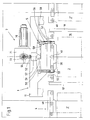
- FIG. 1 shows a processing machine according to the invention with the inventive Tensioner.
- the processing machine 1 is for only partially drawn for better clarity. In particular the frame is only partially hinted at.
- the machining room 16 of the processing machine is limited on the one hand through the housing and the other through doors 10, 10 '.
- the processing machine is used for any 2 goods To make edits.
- the goods 2 are from one Transport device 4 transported into the processing space 16.
- a good hangs as workpiece 2 on a pallet 20.
- Fig. 1 are total three goods 2, 2 ', 2 "are indicated.
- the good 2 is located here in the middle in the processing machine, the good 2 '' is already have been transported out of the processing room, the Processing door 10 is already closed again. The next one Workpiece 2 'is already at the door 10' for further Processing ready.
- the transport device 4 is, for example, made of rollers 40 existing roller conveyor formed.
- the tensioning device 5 according to the invention is used in the here Embodiment shown the pallet 20 in the processing room 16 to span. Even if the interaction of the Clamping device 5 with a pallet 20 is shown Invention not limited to this.
- the pallet 20 is a special case of the good 2. The workpiece 2 be excited directly.
- the clamping device 5 is formed by a plurality of holders 53, which in turn have the clamping bolt 55.
- the exact design of the holder 53 is shown in FIG. 2.
- the clamping bolts 55 lead in for tensioning or indexing vertical movement 59 out.
- a drive 7 is used for this Drive 7 is formed by a motor 70, which has a gearbox 71 drives a drive shaft 72.
- On the drive shaft 72 is a connecting rod 54, which the rotational movement of the drive shaft translates into a linear motion.
- the connecting rod 54 on the tie rod 57 which in turn ultimately the clamping bolt 55 (if necessary positively guided) actuated.
- the drive shaft 72 supplies several Tension bolt 55 with the necessary movement. It is natural also possible that for each clamping bolt its own, autonomous Drive is provided.
- the tension rod 57 acts on a tensioning beam 50 and the tensioning beam 50 in The embodiment shown here moves two clamping bolts 55. Between the connecting rod 54 and the tension rod 57 is a spring assembly 52 provided for an equalization of the clamping forces, since it per Tensioning device two tensioning beams 50 there to four tensioning points to achieve, which are operated with a motor.
- the tensioning cross member 50 is connected via a joint 51 to the Tension rod 57 connected, which results in certain position tolerances easily compensate.
- the tensioning crossbar may have an effect 50 also articulated on the respective clamping bolts 55.
- clamping bolt 55 instead of a mechanical drive for the clamping bolt 55 it is also possible to use the clamping bolts, for example, hydraulically or to drive pneumatically.
- the machine frame has 11 a guide frame 56 for guiding the clamping bolts 55 on.
- the holder 53 may also be on this connected.
- the guide frame 56 takes the bolt guides 58 for the Clamping bolt 55 on.
- the holder 53 of the tensioning device according to the invention 5 shown in detail.
- the holder 53 is C-like designed to laterally enclose the goods 2, 20.
- the The transport direction is, for example, perpendicular to the plate level.
- the C-like design cleverly includes the edge of the Good 2 or the palette 20, here for example for a Clamping and indexing is inserted.
- the clamping bolt 55 above the pallet 20 provided by a vertical movement 59 to a lower End 61 can dip into a recess 21 of the pallet 20.
- the guidance of the clamping bolt 55 is free of play or extreme backlash.
- Below the pallet 20 there is an exactly adjustable one Support surface 62 is provided. It is part of the clamping plane.
- the exact position of the support 62 is due to the installation of adjustable washers 63 adjustable.
- the pallet becomes non-positive and positive by the clamping bolt inserted into the recess 21 55 between the clamping bolt 55 and the support 62 for Editing purposes held.
- a separating stop 60 is provided. This The separating stop 60 is on the right next to the tensioning pin guide arranged. It now turns out that when the jig 5 is opened, the front end 61 of the clamping bolt 55 does not come out of the recess 21, so the pallet 20 lifted up until it abuts the separating stop 60. The clamping bolt is then forced out of the recess 21 pulled out.
- the clamping bolt 55 has an axial bore 64. This Bore 64 is connected to compressed air supply lines 65. however it is possible before and after retracting the clamping bolt To clean recess 21 for example of chips and the like.
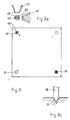
- Fig. 3 the pallet 20 is shown schematically. It deals is an essentially square palette that has the recesses 21 at its edge regions in the corner.
- the recesses 21 are, for example, conical, frustoconical, designed as a cone or cylindrical.
- the workpiece 2 is mounted on the pallet 20.
- the pallet advantageously has at least at each corner a recess 21.
- Fig. 3b is a detailed view of the immersion of the clamping bolt 55 shown schematically in the recess 21. This is a first holder for positioning the pallet serves in a clamping plane.
- the clamping bolt is here on its front, in the recessing end 21 formed as a full cone. This defines the pallet in the clamping plane. But there is still the possibility of one Rotational movement in this clamping plane around this clamping bolt.
- a second one Holder provided, which is preferably diagonally opposite the pallet is used (Fig. 3), which causes the Pallet is set in the clamping plane.
- the clamping bolt has this second holder side flats 65.
- the flats 65 are arranged so that they are on the connecting line of the two interacting with the first and second holders Recesses 21, 21 'are.
- the configuration is in Fig. 3a shown schematically.
- the situation in the recess is through two respective enlarged sectional views in Fig. 3a shown.
- the clamping bolt 55 'therefore only causes a fixation in one direction perpendicular to the pallet diagonal.
- FIG. 3 makes it clear that the recesses 21st are different in the palette 20.
- 3b is one conical recess selected, in recess 21 'according to Fig. 3a it's a frustum-like formation. This does not prepare Problems in use as long as the pallet is not rotated in use becomes. In the event that the pallet is rotated, it is advantageous if all recesses 21 are of the same type. Of another is optionally provided on the pallet, in one To arrange area on the recess 21 of the pallet grooves 66. These allow a certain possibility of compensation. cleverly if these grooves are not arranged in these recesses, those for determining the position or orientation are provided. Flattening of the truncated cones or the guides are also embodiments provided according to the invention, which allow certain compensation options.
Landscapes
- Engineering & Computer Science (AREA)
- Mechanical Engineering (AREA)
- Jigs For Machine Tools (AREA)
- Processing Of Meat And Fish (AREA)
Applications Claiming Priority (2)
| Application Number | Priority Date | Filing Date | Title |
|---|---|---|---|
| DE10319138 | 2003-04-28 | ||
| DE10319138 | 2003-04-28 |
Publications (1)
| Publication Number | Publication Date |
|---|---|
| EP1473111A1 true EP1473111A1 (fr) | 2004-11-03 |
Family
ID=32981149
Family Applications (1)
| Application Number | Title | Priority Date | Filing Date |
|---|---|---|---|
| EP04009959A Withdrawn EP1473111A1 (fr) | 2003-04-28 | 2004-04-27 | Dispositif de serrage |
Country Status (4)
| Country | Link |
|---|---|
| US (1) | US20050001128A1 (fr) |
| EP (1) | EP1473111A1 (fr) |
| CN (1) | CN1569391A (fr) |
| DE (1) | DE102004020779A1 (fr) |
Cited By (1)
| Publication number | Priority date | Publication date | Assignee | Title |
|---|---|---|---|---|
| DE102020212672A1 (de) | 2020-10-07 | 2022-04-07 | Robert Bosch Gesellschaft mit beschränkter Haftung | Positioniereinheit für ein Transfersystem; Transfersystem |
Families Citing this family (5)
| Publication number | Priority date | Publication date | Assignee | Title |
|---|---|---|---|---|
| US7623976B2 (en) * | 2003-06-24 | 2009-11-24 | Cidra Corporate Services, Inc. | System of distributed configurable flowmeters |
| DE102004016820B4 (de) * | 2004-04-01 | 2011-08-18 | Stark Spannsysteme Gmbh | Schnellwechselsystem aus einem Element, insbesondere Werkstückträger, Werkzeugträger, Vorrichtung oder Werkzeug, mit einem Einzugnippel, und mit einem Schnellspannzylinder sowie Verfahren zum Spannen mittels des Schnellwechselsystems |
| DE102011003094B4 (de) * | 2011-01-25 | 2017-01-26 | Hans Lingl Anlagenbau Und Verfahrenstechnik Gmbh & Co. Kg | Transportsystem und Transportverfahren für Formlinge |
| IT201700052288A1 (it) * | 2017-05-15 | 2018-11-15 | Algra S P A | Dispositivo per il bloccaggio automatico di porta-utensili su torni e macchine che effettuano lavorazioni per asportazione di truciolo |
| CN114603200B (zh) * | 2022-05-12 | 2022-10-11 | 四川精诚致远门窗工程有限公司 | 一种门窗铝型材用切割装置 |
Citations (5)
| Publication number | Priority date | Publication date | Assignee | Title |
|---|---|---|---|---|
| US4253559A (en) * | 1979-01-08 | 1981-03-03 | Lasalle Machine Tool, Inc. | Pallet locating and clamping mechanism for a transfer machine |
| DE3422524A1 (de) * | 1984-06-16 | 1985-12-19 | Cross Europa-Werk Gmbh, 7317 Wendlingen | Spann- und positioniervorrichtung fuer eine transfermaschine |
| EP1078713A1 (fr) * | 1999-08-03 | 2001-02-28 | Kabushiki Kaisha Kosmek | Dispositif de serrage avec fonction d'alignement |
| US20020003329A1 (en) * | 2000-06-30 | 2002-01-10 | Hinrich Stave | Positioning and clamping system |
| EP1302278A1 (fr) * | 2001-10-12 | 2003-04-16 | Kabushiki Kaisha Kosmek | Dispositif de serrage |
-
2004
- 2004-04-27 EP EP04009959A patent/EP1473111A1/fr not_active Withdrawn
- 2004-04-27 DE DE102004020779A patent/DE102004020779A1/de not_active Withdrawn
- 2004-04-27 US US10/832,341 patent/US20050001128A1/en not_active Abandoned
- 2004-04-28 CN CNA200410047752XA patent/CN1569391A/zh active Pending
Patent Citations (5)
| Publication number | Priority date | Publication date | Assignee | Title |
|---|---|---|---|---|
| US4253559A (en) * | 1979-01-08 | 1981-03-03 | Lasalle Machine Tool, Inc. | Pallet locating and clamping mechanism for a transfer machine |
| DE3422524A1 (de) * | 1984-06-16 | 1985-12-19 | Cross Europa-Werk Gmbh, 7317 Wendlingen | Spann- und positioniervorrichtung fuer eine transfermaschine |
| EP1078713A1 (fr) * | 1999-08-03 | 2001-02-28 | Kabushiki Kaisha Kosmek | Dispositif de serrage avec fonction d'alignement |
| US20020003329A1 (en) * | 2000-06-30 | 2002-01-10 | Hinrich Stave | Positioning and clamping system |
| EP1302278A1 (fr) * | 2001-10-12 | 2003-04-16 | Kabushiki Kaisha Kosmek | Dispositif de serrage |
Cited By (2)
| Publication number | Priority date | Publication date | Assignee | Title |
|---|---|---|---|---|
| DE102020212672A1 (de) | 2020-10-07 | 2022-04-07 | Robert Bosch Gesellschaft mit beschränkter Haftung | Positioniereinheit für ein Transfersystem; Transfersystem |
| EP3981545A1 (fr) * | 2020-10-07 | 2022-04-13 | Robert Bosch GmbH | Unité de positionnement pour un système de transfert, système de transfert |
Also Published As
| Publication number | Publication date |
|---|---|
| DE102004020779A1 (de) | 2005-01-05 |
| US20050001128A1 (en) | 2005-01-06 |
| CN1569391A (zh) | 2005-01-26 |
Similar Documents
| Publication | Publication Date | Title |
|---|---|---|
| EP0985488B1 (fr) | Dispositif de serrage pour pièces multiples | |
| EP3074152B1 (fr) | Système d'outils pour presse de pliage | |
| DE3823635C2 (fr) | ||
| EP0900618A1 (fr) | Plaque de montage pour une pièce à usiner | |
| DE2817217A1 (de) | Werkzeugmaschine | |
| EP0742081A2 (fr) | Etan universel de précision pour une machine-outil | |
| EP0480191B1 (fr) | Equipement pour l'usinage de barres | |
| CH668733A5 (de) | Vorrichtung zur halterung und handhabung eines flachen gegenstandes. | |
| EP1473111A1 (fr) | Dispositif de serrage | |
| DE102019100257A1 (de) | Werkzeugmaschine | |
| DE602006000992T2 (de) | Maschine zur Herstellung von Türrahmen | |
| DE10025614A1 (de) | Vorrichtung zum Greifen und Transportieren von Werkstücken in Drehmaschinen | |
| DE69813384T2 (de) | Zapfenlochwerkzeug für Einstechmaschinen, insbesondere für mehrschichtige Holzbalken und dergleichen | |
| DE10039525A1 (de) | Werkzeugmaschine mit Greifer und oder Werkzeugmagazinsystem | |
| DE202004004636U1 (de) | Zentrierspannvorrichtung | |
| DE3540016A1 (de) | Gewerblicher montageroboter | |
| DE69412045T2 (de) | Halter für Teile, insbesondere für eine Bearbeitungsstation mit einem Drehtisch | |
| DE102012020585A1 (de) | Vorrichtung und Verfahren zum Fixieren von flächigen, ansaugfähigen Objekten | |
| EP0456850A1 (fr) | Dispositif de profilage longitudinal des pièces en bois | |
| DE102010018610B4 (de) | Außen-Räummaschine für Schlosskerne und Verfahren zum Außenräumen | |
| DE10334285A1 (de) | Bearbeitungsmaschine mit zwei Bearbeitungseinheiten | |
| DE10011754A1 (de) | Vorrichtung zum vibrationsarmen Spannen von flächigen Werkstücken an einer spanenden Bearbeitungsmaschine | |
| DE102008005956B4 (de) | Bearbeitungszentrum mit Werkstückwechsler und Rüstplatz | |
| EP1473112A1 (fr) | Machine outil | |
| DE202012001836U1 (de) | Antriebseinrichtung für eine Bearbeitungsmaschine |
Legal Events
| Date | Code | Title | Description |
|---|---|---|---|
| PUAI | Public reference made under article 153(3) epc to a published international application that has entered the european phase |
Free format text: ORIGINAL CODE: 0009012 |
|
| AK | Designated contracting states |
Kind code of ref document: A1 Designated state(s): AT BE BG CH CY CZ DE DK EE ES FI FR GB GR HU IE IT LI LU MC NL PL PT RO SE SI SK TR |
|
| AX | Request for extension of the european patent |
Extension state: AL HR LT LV MK |
|
| 17P | Request for examination filed |
Effective date: 20050118 |
|
| AKX | Designation fees paid |
Designated state(s): AT BE BG CH CY CZ DE DK EE ES FI FR GB GR HU IE IT LI LU MC NL PL PT RO SE SI SK TR |
|
| RAP1 | Party data changed (applicant data changed or rights of an application transferred) |
Owner name: GROB-WERKE GMBH & CO. KG |
|
| 17Q | First examination report despatched |
Effective date: 20070226 |
|
| STAA | Information on the status of an ep patent application or granted ep patent |
Free format text: STATUS: THE APPLICATION IS DEEMED TO BE WITHDRAWN |
|
| 18D | Application deemed to be withdrawn |
Effective date: 20070710 |