EP1473201A1 - Stromversorgungskreis - Google Patents
Stromversorgungskreis Download PDFInfo
- Publication number
- EP1473201A1 EP1473201A1 EP03703157A EP03703157A EP1473201A1 EP 1473201 A1 EP1473201 A1 EP 1473201A1 EP 03703157 A EP03703157 A EP 03703157A EP 03703157 A EP03703157 A EP 03703157A EP 1473201 A1 EP1473201 A1 EP 1473201A1
- Authority
- EP
- European Patent Office
- Prior art keywords
- current
- igniter
- supplied
- μsec
- power source
- Prior art date
- Legal status (The legal status is an assumption and is not a legal conclusion. Google has not performed a legal analysis and makes no representation as to the accuracy of the status listed.)
- Granted
Links
Images




Classifications
-
- B—PERFORMING OPERATIONS; TRANSPORTING
- B60—VEHICLES IN GENERAL
- B60R—VEHICLES, VEHICLE FITTINGS, OR VEHICLE PARTS, NOT OTHERWISE PROVIDED FOR
- B60R21/00—Arrangements or fittings on vehicles for protecting or preventing injuries to occupants or pedestrians in case of accidents or other traffic risks
- B60R21/01—Electrical circuits for triggering passive safety arrangements, e.g. airbags, safety belt tighteners, in case of vehicle accidents or impending vehicle accidents
- B60R21/017—Electrical circuits for triggering passive safety arrangements, e.g. airbags, safety belt tighteners, in case of vehicle accidents or impending vehicle accidents including arrangements for providing electric power to safety arrangements or their actuating means, e.g. to pyrotechnic fuses or electro-mechanic valves
-
- F—MECHANICAL ENGINEERING; LIGHTING; HEATING; WEAPONS; BLASTING
- F42—AMMUNITION; BLASTING
- F42B—EXPLOSIVE CHARGES, e.g. FOR BLASTING, FIREWORKS, AMMUNITION
- F42B3/00—Blasting cartridges, i.e. case and explosive
- F42B3/10—Initiators therefor
- F42B3/12—Bridge initiators
- F42B3/125—Bridge initiators characterised by the configuration of the bridge initiator case
Definitions
- the present invention relates to a current supplying circuit which supplies an electric current for actuating an igniter at a time of actuation of an air bag gas generator, an air bag system using the current supplying circuit and a method of actuating an igniter.
- An air bag system for protecting a passenger from an impact at a time of collision of a vehicle is indispensable, and the air bag system needs to be reduced in weight from a demand for reducing weight of a whole vehicle.
- kinds and the total number of air bags such as an air bag for a driver side, an air bag for a passenger side next to the driver, an air bag for a rear seat side, and an air bag for an side impact are increasing, and therefore, a lighter air bag system is in greater demand.
- an electronic control unit connected to a power source (a battery in a vehicle) and an impact detecting sensor are individually connected to individual gas generators (a gas generator and an air bag are accommodated in a module case).
- a power source a battery in a vehicle
- an impact detecting sensor is individually connected to individual gas generators (a gas generator and an air bag are accommodated in a module case).
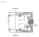
- An aspect of the connection between the ECU and the individual gas generators is shown in Fig. 4.
- the ECU and each module case are connected to each other through two conducting wires (lead wires), and an electric current at a time of actuation of an igniter is supplied from a battery.
- a gas generator is not actuated.
- a capacitor for backup power source is incorporated into the ECU.
- this capacitor has to actuate all igniters, and therefore, the capacitor is obligated to have a large capacitance (namely, weight), which makes the ECU so large.
- An object of the present invention is to provide a current supplying circuit in which a capacitance of a capacitor for backup power source provided in an ECU is reduced and that contributes weight reduction of an entire air bag system, an air bag system using the current supplying circuit, and a method for actuating an igniter.
- the present inventors started studying in view of reducing an amount of ignition energy required for actuating individual igniters.
- a heat generating portion of the igniter In order to inflate an air bag within a required period at a time of vehicle collision, a heat generating portion of the igniter has to generate a heat instantaneously to securely ignite and burn a priming in contact with the heat generating portion.
- ⁇ J ignition energy
- the inventors repeatedly made a study about a relationship between a pulse width ( ⁇ sec) of the current supplied to the heat generating portion and an amount of ignition energy.
- the inventors found that the priming can be ignited and burnt with ignition energy of about 1000 ⁇ J, provided that the resistance value of the heat generating portion is 2 ⁇ and the priming is a mixture (ZPP) of zirconium and potassium perchlorate, or a mixture of another priming such as hafnium hydride or titanium hydride and potassium perchlorate. They further found the range of pulse width of the current imparting the ignition energy, and completed the present invention.
- the present invention provides, as one means for solving the above problem, a current supplying circuit which supplies an electric current required to actuate an electric igniter arranged in a gas generator at a time of actuation of the air bag gas generator, wherein a current obtained from an external power source is supplied as an ignition pulse for actuating the igniter, and the current is supplied such that the width of the ignition pulse becomes 20 to 500 ⁇ sec.
- the electric current for actuating an igniter flows from a power source (a battery) at 1.2 A for about 2 msec, that is, at a relatively low current for a long time
- the waveform (ignition pulse) of the ignition current (a vertical axis denotes a current value (A) and a horizontal axis denotes a time ( ⁇ sec)) becomes rectangular.
- a current is supplied at a relatively high current value for a short time, that is, such that the width of the ignition pulse at this time is 20 to 500 ⁇ sec, preferably 30 to 200 ⁇ sec, and more preferably 40 to 100 ⁇ sec.
- the present invention provides, as another means for solving the above problem, a current supplying circuit supplying an electric current required for actuating an electric igniter arranged in a gas generator at a time of actuation of the gas generator for an air bag, and comprising a switch circuit for opening or closing a current path for actuating the igniter, a pulse generator for providing a controlling pulse for opening or closing the switch circuit, and the switch circuit provided between the current path and an external power source, wherein an electric current obtained from the external power source is supplied as an ignition pulse for actuating the igniter by the switch circuit, and the current is further adjusted such that the width of the ignition pulse is 20 to 500 ⁇ sec to be supplied.
- a disconnection detecting circuit for detecting a disconnection of the current path is further provided, and a switch circuit is not provided between the current path and the disconnection detecting circuit.
- a voltage transformer and a capacitor which stores a current supplied from the external power source to supply a current instead of the external power source when supplying a current from the external power source is interruptted are further provided.
- the voltage transformer is for conducting voltage transform for an interface or an MCU (Micro Computer Unit).
- the switch circuit a thyristor, a MOS-FET or a bipolar transistor or the like can be used, and the switch circuit can be provided at both or one of a positive and negative sides of the path supplying the current.
- a current obtained from the external power source is supplied as an ignition pulse for actuating the igniter, and the current is supplied such that the width of the ignition pulse is 20 to 500 ⁇ sec, preferably 30 to 200 ⁇ sec, and more preferably 40 to 100 ⁇ sec.
- an amount of current (an amount of ignition energy) required for actuating individual igniters can be reduced, so that an amount of current required for all igniters, namely for the whole air bag system, can be reduced. For this reason, a volume of a capacitor for backup power source incorporated into the ECU can be made smaller and therefore the ECU itself can also be made compact.
- the present invention provides, as another means for solving the above problem, an air bag system comprising an ECU connected to a power source and an impact detecting sensor, and plural module cases connected to the ECU and accommodating plural gas generators and plural air bags, each of the ECU and individual gas generators being connected separately by conductors, wherein the above-described current supplying circuit is provided in the ECU.
- the present invention provides, as another means for solving the above problem, a method of actuating an electric igniter in which the igniter is arranged in a gas generator for an air bag to be actuated by supplying a current, wherein a current obtained from an external power source is supplied as an ignition pulse for actuating the igniter and the current is supplied such that the width of the ignition pulse is 20 to 500 ⁇ sec.
- a current in view of reducing an amount of current, such that the width of the ignition pulse is 40 to 100 ⁇ sec.
- the weight of the whole air bag system mounted on a vehicle can be reduced while securing operation performance similar to that in the conventional one.
- Fig. 1 is a conceptual diagram of a current supplying circuit of the present invention, and the current supplying circuit is provided in an ECU.
- a current supplying circuit is constituted by arranging respective elements of at least a switch circuit, a pulse generator, a disconnection detecting circuit, a voltage transformer, a capacitor and the like on a substrate, and it is provided in a midway of a current path connecting a battery which is an external power source and igniters incorporated into gas generators. Two current paths are provided for each igniter and formed by two conducting wires (lead wires).
- the switch circuit which opens or closes the current path and blocks a current when it is unnecessary to actuate an igniter to start supplying a current at a time of actuation of the igniter is provided in the current supplying circuit, and one switch circuit is provided for each current path (for each one lead wire). When the switch circuit is opened, a current never flows into the current path.
- the switch circuit and the pulse generator are connected by conductors, and the switch circuit is opened or closed by sending a controlling pulse instructing to open or close the switch circuit from the pulse generator.
- a command for transmitting a controlling pulse to the pulse generator is sent from an MCU upon receipt of an instruction from an impact detecting sensor.
- the switch circuit is formed of a thyristor, a MOS-FET, a bipolar transistor or the like. It is desirable, in view of preventing an erroneous operation, that the switch circuits is provided on each of positive and negative sides of the current path, as shown in Fig. 1, but it may be provided on only the positive side. For example, when that a current pulse with a waveform width of 100 ⁇ sec is applied from the pulse generator, the switch is closed for 100 ⁇ sec so that a current from the voltage transformer flows to a heat generating portion of the igniter as a pulse with a width of 100 ⁇ sec. By applying a pulse with a predetermined time-width to the heat generating portion of the igniter in this manner, heat is generated at the heat generating portion to ignite and burn a priming.
- the disconnection detecting circuit is for detecting abnormality of an igniter (abnormality of the heat generating portion of the igniter), and it is connected with the current path, but a switch circuit is not provided between the disconnection detecting circuit and the current path. For this reason, when the igniter is not being actuated (when a vehicle is running normally), a weak electric current for detecting disconnection is always flowing from the disconnection detecting circuit, so that abnormality of the igniter can be detected promptly and such abnormality is notified by an alarm lamp actuated in a linkage manner, which allows early exchange of parts.
- the capacitor is for storing a current supplied from the battery and supplying an electric current instead of the battery when supplying the current from the battery is interrupted. Therefore, the capacitor is connected to all elements within the current supplying circuit directly or indirectly through conductors.
- the capacitor is provided in a midway of the current path from the battery to the current supplying circuit, but a current is sent to the current supplying circuit by only the battery unless a disconnection occurs between the battery and the ECU.
- the voltage transformer is for performing voltage transformation for an interface or an MCU
- a ROM is for storing patterns of signals required for actuating each air bag system
- the interface is for optimizing external signals in order to transmit them to the MCU, the pulse generator and the disconnection detecting circuit.
- a capacitor stores therein a current required as a backup power source of a current supplied from the battery. Then, a test current (weak current) for detecting disconnection flows from the disconnection detecting circuit, so that abnormality of the igniter (a loose contact between the heat generating portion and the priming of the igniter, or a disconnection of the heat generating portion) is detected.
- a contacting state between the heat generating portion of the igniter and the priming has to be good (the heat generating portion and the priming has to be brought in press-contact with each other).
- the heat generating portion and the priming has to be brought in press-contact with each other.
- the heat generating portion is disconnected or have been half-disconnected, a similar malfunction occurs. For this reason, by recording information for detecting the malfunction in the integrated circuit, an inferior product can be removed at a time of shipping, and by detecting abnormality at a practical use (while driving a vehicle), a prompt exchange can be performed.
- an instruction from the impact detecting sensor is transmitted to the ECU, and an instruction for closing the switch circuit is transmitted to the pulse generator via the MCU.
- a current from the battery is sent to the igniter via the current path as an ignition pulse for actuating the igniter (the width is 20 to 500 ⁇ sec, preferably 30 to 200 ⁇ sec and more preferably 40 to 100 ⁇ sec) while a controlling pulse is flowing into the switch circuit from the pulse generator.
- the heat generating portion of the igniter generates heat, so that the priming coming in contact with the heat generating portion is ignited.
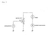
- a test circuit shown in Fig. 7 was used as the current supplying circuit, and it was recorded such that each switch circuit was supplied with currents supplied from the power source, being adjusted to have ignition pulses with widths of 15 ⁇ sec, 40 ⁇ sec, 100 ⁇ sec and 2000 ⁇ sec.
- a general igniter shown in Fig. 3 was used as the igniter.
- the igniter were connected to conducting wires at two pin portions, and it was connected to a direct-current source via the current supplying circuit shown in Fig. 7.
- Fig. 2 shows a relationship between a pulse width ( ⁇ sec) of an ignition pulse and ignition energy ( ⁇ J), and respective points are 15 ⁇ sec, 40 ⁇ sec, 100 ⁇ sec and 2000 ⁇ sec in an ascending order.
- the minimum ignition energies at all the pulse widths of 15 ⁇ sec, 40 ⁇ sec, 100 ⁇ sec and 2000 ⁇ sec are shown in Fig. 2, from which it was confirmed that the priming could sufficiently be ignited and burnt even in a pulse width in the range of 40 to 100 ⁇ sec, which corresponded to the ignition energy of about 1000 ⁇ J.
- the ignition energy obtained in the pulse width in the range of 40 to 100 ⁇ sec was reduced down to 1/5 of the ignition energy obtained at the conventional pulse width of 2000 ⁇ sec (2 msec).
- the ignition pulse width By setting the ignition pulse width to a predetermined range with such a current supplying circuit, an amount of a current (an amount of ignition energy) required for actuating individual igniters normally can be reduced, so that an amount of current (an amount of ignition energy) required actuating all the igniters normally can also be reduced.
- the capacitance (namely weight) of the capacitor for a backup power source can also be made smaller and the ECU itself can be made compact.
- the current supplying circuit of the present invention can be applied to various inflators (gas generators) such as an inflator for an air bag for a driver side, an inflator for an air bag for a passenger side next to the driver, an inflator for a side air bag, an inflator for a curtain air bag, and an inflator for a knee-bolster air bag, an inflator for an inflatable seat belt, an inflator for a tubular system, and an inflator for a pretensioner.
- inflators gas generators
- Fig. 5 and Fig. 6 are sectional views of general gas generators in the radial direction, Fig. 5 showing a gas generator of a single type having a single igniter, and Fig. 6 showing a gas generator of a dual type having two igniter.
- an air bag system mounted in a vehicle comprises an ECU connected to a power source (a battery) and an impact detecting sensor, and plural module cases accommodating plural gas generators and air bags, which is connected to the ECU, wherein each of the ECU and individual gas generators is connected separately by conductors, and the current supplying circuit as shown in Fig. 1 is provided in the ECU.
- one of the single type shown in Fig. 5 or one of the dual type shown in Fig. 6 can be used, and as an igniter incorporated into the gas generator, one shown in Fig. 3 can be used.
- a weak current for disconnection detecting of the heat generating portion flows to the igniters of the gas generators from the current supplying circuit to detect abnormality in the igniters. If abnormality is detected, the abnormality is announced by an alarm lamp actuated in linkage with the air bag system or the like so that an early exchange of parts can be made and a safety can therefore be ensured. Further, charging of the capacitor in the current supplying circuit from the power source can be made.
- a transfer charge in the gas generator shown in Fig. 5 or Fig. 6, and further the gas generating agent is ignited and burnt to generate a gas.
- the generated gas is discharged from gas discharging ports to inflate an air bag accommodated in the module case together with the gas generator.
- an amount of a current (an amount of ignition energy) required for actuating individual igniters normally is reduced, so that an amount of a current (an amount of ignition energy) required for actuating all the igniters normally can also be reduced.
- the capacitance (weight) of the capacitor for a backup power source can also be made smaller and the ECU itself can be made compact. For this reason, the weight of the whole air bag system can be reduced.
- the air bag system of the present invention can be applied to various inflators (gas generators) such as an inflator for an air bag for a driver side, an inflator for an air bag for a passenger side next to the driver, an inflator for a side air bag, an inflator for a curtain air bag, and an inflator for a knee-bolster air bag, an inflator for an inflatable seat belt, an inflator for a tubular system, and an inflator for a pretensioner.
- inflators gas generators
Landscapes
- Engineering & Computer Science (AREA)
- General Engineering & Computer Science (AREA)
- Mechanical Engineering (AREA)
- Air Bags (AREA)
- Automotive Seat Belt Assembly (AREA)
Applications Claiming Priority (3)
| Application Number | Priority Date | Filing Date | Title |
|---|---|---|---|
| JP2002026776A JP2003226223A (ja) | 2002-02-04 | 2002-02-04 | 電流供給回路 |
| JP2002026776 | 2002-02-04 | ||
| PCT/JP2003/001121 WO2003066389A1 (en) | 2002-02-04 | 2003-02-04 | Current supply circuit |
Publications (3)
| Publication Number | Publication Date |
|---|---|
| EP1473201A1 true EP1473201A1 (de) | 2004-11-03 |
| EP1473201A4 EP1473201A4 (de) | 2009-11-18 |
| EP1473201B1 EP1473201B1 (de) | 2017-06-14 |
Family
ID=27677824
Family Applications (1)
| Application Number | Title | Priority Date | Filing Date |
|---|---|---|---|
| EP03703157.2A Expired - Lifetime EP1473201B1 (de) | 2002-02-04 | 2003-02-04 | Stromversorgungskreis zur Erzeugung von Zündimpulsen von 20 bis 500 Mikrosekunden zur Anwendung in Insassenschutzsystemen |
Country Status (3)
| Country | Link |
|---|---|
| EP (1) | EP1473201B1 (de) |
| JP (1) | JP2003226223A (de) |
| WO (1) | WO2003066389A1 (de) |
Families Citing this family (1)
| Publication number | Priority date | Publication date | Assignee | Title |
|---|---|---|---|---|
| JP2012144056A (ja) * | 2011-01-06 | 2012-08-02 | Ihi Aerospace Co Ltd | 火工品点火装置及び火工品点火方法 |
Family Cites Families (7)
| Publication number | Priority date | Publication date | Assignee | Title |
|---|---|---|---|---|
| EP0615887A1 (de) | 1993-03-18 | 1994-09-21 | Delco Electronics Corporation | Ergänzende, aufblasbare Rückhaltevorrichtung |
| JPH08188114A (ja) * | 1995-01-09 | 1996-07-23 | Tokai Rika Co Ltd | エアバッグ作動制御装置 |
| US5732634A (en) * | 1996-09-03 | 1998-03-31 | Teledyne Industries, Inc. | Thin film bridge initiators and method of manufacture |
| JPH1148908A (ja) * | 1997-07-31 | 1999-02-23 | Fujitsu Ten Ltd | エアバッグ装置の故障検出装置 |
| DE19749856B4 (de) * | 1997-11-11 | 2004-06-09 | Siemens Ag | Verfahren und Zündschaltung zur Auslösung eines Insassenschutzsystems |
| JPH11310102A (ja) * | 1998-04-30 | 1999-11-09 | Kansei Corp | 車両用乗員保護装置 |
| US6324979B1 (en) * | 1999-12-20 | 2001-12-04 | Vishay Intertechnology, Inc. | Electro-pyrotechnic initiator |
-
2002
- 2002-02-04 JP JP2002026776A patent/JP2003226223A/ja active Pending
-
2003
- 2003-02-04 EP EP03703157.2A patent/EP1473201B1/de not_active Expired - Lifetime
- 2003-02-04 WO PCT/JP2003/001121 patent/WO2003066389A1/ja not_active Ceased
Also Published As
| Publication number | Publication date |
|---|---|
| EP1473201B1 (de) | 2017-06-14 |
| JP2003226223A (ja) | 2003-08-12 |
| WO2003066389A1 (en) | 2003-08-14 |
| EP1473201A4 (de) | 2009-11-18 |
Similar Documents
| Publication | Publication Date | Title |
|---|---|---|
| JP4065582B2 (ja) | 自動車用エアバッグ・システム | |
| US7069860B2 (en) | Igniter for air bag system | |
| EP1582417A1 (de) | Zündpillentreiberschaltung für Airbaganwendungen | |
| US7155353B2 (en) | Method for determining charging capacitance of capacitor | |
| US7165784B2 (en) | Current supplying circuit | |
| US6037674A (en) | Circuit and method of current limiting a half-bridge driver | |
| KR101729621B1 (ko) | 팽창가능 제한을 위한 이중 발동 시스템 | |
| US7168737B2 (en) | Integrated circuit for air bag system | |
| EP1473201B1 (de) | Stromversorgungskreis zur Erzeugung von Zündimpulsen von 20 bis 500 Mikrosekunden zur Anwendung in Insassenschutzsystemen | |
| US20030234527A1 (en) | Igniter for air bag system | |
| EP1798115B1 (de) | Verfahren zur Bestimmung der Ladekapazität eines Kondensators | |
| JP3996410B2 (ja) | エアバッグシステム用点火器 | |
| JP4116608B2 (ja) | 電流供給回路 | |
| JP3582822B2 (ja) | 車両用乗員保護装置及びその制御方法 | |
| JPWO2002030719A1 (ja) | エアバッグの起動装置 | |
| EP1468879A1 (de) | Airbagsystem | |
| US6979020B2 (en) | Air bag system | |
| JP2001525288A (ja) | 点火回路及び点火回路の作動方法 | |
| JP4037123B2 (ja) | エアバッグシステム用集積回路 | |
| JP4031258B2 (ja) | エアバッグシステム用点火器 | |
| JP2005306074A (ja) | 乗員保護システムの作動方法、ガス発生器及び乗員保護システム用電子制御ユニット、乗員保護システム | |
| MXPA01007320A (en) | Igniter |
Legal Events
| Date | Code | Title | Description |
|---|---|---|---|
| PUAI | Public reference made under article 153(3) epc to a published international application that has entered the european phase |
Free format text: ORIGINAL CODE: 0009012 |
|
| 17P | Request for examination filed |
Effective date: 20040713 |
|
| AK | Designated contracting states |
Kind code of ref document: A1 Designated state(s): AT BE BG CH CY CZ DE DK EE ES FI FR GB GR HU IE IT LI LU MC NL PT SE SI SK TR |
|
| RIN1 | Information on inventor provided before grant (corrected) |
Inventor name: ODA, SHINGO Inventor name: OKAMOTO, MITSUYASU |
|
| RAP1 | Party data changed (applicant data changed or rights of an application transferred) |
Owner name: DAICEL CHEMICAL INDUSTRIES, LTD. |
|
| A4 | Supplementary search report drawn up and despatched |
Effective date: 20091019 |
|
| 17Q | First examination report despatched |
Effective date: 20100729 |
|
| RIC1 | Information provided on ipc code assigned before grant |
Ipc: F42B 3/12 20060101ALI20161128BHEP Ipc: B60R 21/26 20060101AFI20161128BHEP |
|
| GRAP | Despatch of communication of intention to grant a patent |
Free format text: ORIGINAL CODE: EPIDOSNIGR1 |
|
| INTG | Intention to grant announced |
Effective date: 20170116 |
|
| GRAS | Grant fee paid |
Free format text: ORIGINAL CODE: EPIDOSNIGR3 |
|
| GRAA | (expected) grant |
Free format text: ORIGINAL CODE: 0009210 |
|
| AK | Designated contracting states |
Kind code of ref document: B1 Designated state(s): DE FR |
|
| REG | Reference to a national code |
Ref country code: DE Ref legal event code: R096 Ref document number: 60350320 Country of ref document: DE |
|
| REG | Reference to a national code |
Ref country code: FR Ref legal event code: PLFP Year of fee payment: 16 |
|
| REG | Reference to a national code |
Ref country code: DE Ref legal event code: R097 Ref document number: 60350320 Country of ref document: DE |
|
| PLBE | No opposition filed within time limit |
Free format text: ORIGINAL CODE: 0009261 |
|
| STAA | Information on the status of an ep patent application or granted ep patent |
Free format text: STATUS: NO OPPOSITION FILED WITHIN TIME LIMIT |
|
| 26N | No opposition filed |
Effective date: 20180315 |
|
| PGFP | Annual fee paid to national office [announced via postgrant information from national office to epo] |
Ref country code: DE Payment date: 20220217 Year of fee payment: 20 |
|
| PGFP | Annual fee paid to national office [announced via postgrant information from national office to epo] |
Ref country code: FR Payment date: 20220216 Year of fee payment: 20 |
|
| REG | Reference to a national code |
Ref country code: DE Ref legal event code: R071 Ref document number: 60350320 Country of ref document: DE |