EP1473204B1 - Système de réglage de la dynamique de marche d'un véhicule - Google Patents
Système de réglage de la dynamique de marche d'un véhicule Download PDFInfo
- Publication number
- EP1473204B1 EP1473204B1 EP04252467A EP04252467A EP1473204B1 EP 1473204 B1 EP1473204 B1 EP 1473204B1 EP 04252467 A EP04252467 A EP 04252467A EP 04252467 A EP04252467 A EP 04252467A EP 1473204 B1 EP1473204 B1 EP 1473204B1
- Authority
- EP
- European Patent Office
- Prior art keywords
- vdc
- differential
- threshold value
- initiation threshold
- limited state
- Prior art date
- Legal status (The legal status is an assumption and is not a legal conclusion. Google has not performed a legal analysis and makes no representation as to the accuracy of the status listed.)
- Expired - Lifetime
Links
Images

Classifications
-
- B—PERFORMING OPERATIONS; TRANSPORTING
- B60—VEHICLES IN GENERAL
- B60T—VEHICLE BRAKE CONTROL SYSTEMS OR PARTS THEREOF; BRAKE CONTROL SYSTEMS OR PARTS THEREOF, IN GENERAL; ARRANGEMENT OF BRAKING ELEMENTS ON VEHICLES IN GENERAL; PORTABLE DEVICES FOR PREVENTING UNWANTED MOVEMENT OF VEHICLES; VEHICLE MODIFICATIONS TO FACILITATE COOLING OF BRAKES
- B60T8/00—Arrangements for adjusting wheel-braking force to meet varying vehicular or ground-surface conditions, e.g. limiting or varying distribution of braking force
- B60T8/17—Using electrical or electronic regulation means to control braking
- B60T8/1755—Brake regulation specially adapted to control the stability of the vehicle, e.g. taking into account yaw rate or transverse acceleration in a curve
-
- B—PERFORMING OPERATIONS; TRANSPORTING
- B60—VEHICLES IN GENERAL
- B60T—VEHICLE BRAKE CONTROL SYSTEMS OR PARTS THEREOF; BRAKE CONTROL SYSTEMS OR PARTS THEREOF, IN GENERAL; ARRANGEMENT OF BRAKING ELEMENTS ON VEHICLES IN GENERAL; PORTABLE DEVICES FOR PREVENTING UNWANTED MOVEMENT OF VEHICLES; VEHICLE MODIFICATIONS TO FACILITATE COOLING OF BRAKES
- B60T8/00—Arrangements for adjusting wheel-braking force to meet varying vehicular or ground-surface conditions, e.g. limiting or varying distribution of braking force
- B60T8/17—Using electrical or electronic regulation means to control braking
- B60T8/176—Brake regulation specially adapted to prevent excessive wheel slip during vehicle deceleration, e.g. ABS
- B60T8/1769—Brake regulation specially adapted to prevent excessive wheel slip during vehicle deceleration, e.g. ABS specially adapted for vehicles having more than one driven axle, e.g. four-wheel drive vehicles
-
- B—PERFORMING OPERATIONS; TRANSPORTING
- B60—VEHICLES IN GENERAL
- B60T—VEHICLE BRAKE CONTROL SYSTEMS OR PARTS THEREOF; BRAKE CONTROL SYSTEMS OR PARTS THEREOF, IN GENERAL; ARRANGEMENT OF BRAKING ELEMENTS ON VEHICLES IN GENERAL; PORTABLE DEVICES FOR PREVENTING UNWANTED MOVEMENT OF VEHICLES; VEHICLE MODIFICATIONS TO FACILITATE COOLING OF BRAKES
- B60T2201/00—Particular use of vehicle brake systems; Special systems using also the brakes; Special software modules within the brake system controller
- B60T2201/14—Electronic locking-differential
-
- B—PERFORMING OPERATIONS; TRANSPORTING
- B60—VEHICLES IN GENERAL
- B60T—VEHICLE BRAKE CONTROL SYSTEMS OR PARTS THEREOF; BRAKE CONTROL SYSTEMS OR PARTS THEREOF, IN GENERAL; ARRANGEMENT OF BRAKING ELEMENTS ON VEHICLES IN GENERAL; PORTABLE DEVICES FOR PREVENTING UNWANTED MOVEMENT OF VEHICLES; VEHICLE MODIFICATIONS TO FACILITATE COOLING OF BRAKES
- B60T2270/00—Further aspects of brake control systems not otherwise provided for
- B60T2270/30—ESP control system
- B60T2270/302—ESP control system for all-wheel drive vehicles
Definitions
- the present invention relates to a vehicle dynamics control (VDC) apparatus for an automotive vehicle with a vehicle dynamics control (VDC) system capable of controlling a yawing motion of the vehicle by controlling a braking force of at least one road wheel, and a differential limiting device capable of limiting a differential motion between front and rear wheel axles and/or a differential motion between left and right wheel axles, and specifically to the improvement of vehicle dynamics control technologies in a differential limited state and in a differential non-limited state.
- VDC vehicle dynamics control
- JP2000-344077 Japanese Patent Provisional Publication No. 2000-344077
- the vehicle-behavior control apparatus disclosed in JP2000-344077 operates to reduce engine power output and additionally to inhibit braking force control for each individual road wheel in the center-differential locked state.
- vehicle behavior control suitable for a two-wheel-drive (2WD) mode vehicle behavior control peculiar to a four-wheel-drive (4WD) mode has to be used.
- any unnatural feeling e.g., an unintended vehicle deceleration
- a vehicle dynamics control (VDC) apparatus for an automotive vehicle with a differential limiting device capable of limiting at least one of a differential motion between front and rear wheel axles and a differential motion between left and right wheel axles, comprises a VDC system that controls a braking force of at least one road wheel to control vehicle cornering behavior depending on a vehicle's turning condition independently of a driver's braking action, and the VDC system advancing a VDC initiation timing used in a differential limited state in which at least one of the front-and-rear wheel axle differential motion and the left-and-right wheel axle differential motion is limited, in comparison with a VDC initiation timing used in a differential non-limited state in which the front-and-rear wheel axle differential motion and the left-and-right wheel axle differential motion are allowed.
- VDC vehicle dynamics control
- a method of controlling vehicle cornering behavior of an automotive vehicle with a differential limiting device capable of limiting at least one of differential motion between front and rear wheel axles and differential motion between left and right wheel axles comprising controlling a braking force of at least one road wheel to execute vehicle dynamics control (VDC) by which the vehicle cornering behavior is controlled depending on a vehicle's turning condition independently of a driver's braking action, detecting whether the vehicle is in a differential limited state in which at least one of the front-and-rear wheel axle differential motion and the left-and-right wheel axle differential motion is limited or in a differential non-limited state in which the front-and-rear wheel axle differential motion and the left-and-right wheel axle differential motion are allowed, and advancing a VDC initiation timing used in the differential limited state, in comparison with a VDC initiation timing used in the differential non-limited state.
- VDC vehicle dynamics control
- VDC vehicle dynamics control
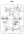
- transfer clutch 10 serves as a differential limiting means that limits differential motion between a front wheel axle for front-left and front-right road wheels 15 and 16 and a rear wheel axle for rear-left and rear-right road wheels 8 and 9.
- engine power output driving torque
- rear-left and rear-right axle driveshafts 5 and 6 rear-left and rear-right wheels 8 and 9, so as to attain a rear-wheel-drive mode (a 2WD mode) in which the differential motion between front and rear wheel axles is allowed.
- a differential limited state in an engaged state of transfer clutch 10) in which a front-and-rear wheel speed difference is limited, part of engine power output (driving torque) is delivered through rear propeller shaft 3, rear differential 4, and rear axle driveshafts 5 and 6 to rear wheels 8 and 9.
- the remaining driving torque is transferred through a front propeller shaft 11 to a front differential 12, and then transferred via front-left and front-right axle driveshafts 13 and 14 to front-left and front-right wheels 15 and 16, so as to attain a four-wheel-drive mode (a 4WD mode) in which the differential motion between front and rear wheel axles is limited.
- Differential limiting clutch 7 (exactly, a rear differential limiting clutch) is provided between rear axle driveshafts 5 and 6.
- Differential limiting clutch 7 serves as a differential limiting means that limits differential motion between a rear-left wheel axle (rear-left axle driveshaft 5) for rear-left road wheel 8 and a rear-right wheel axle (rear-right axle driveshaft 6).
- rear differential 4 When fully engaging differential limiting clutch 7, the differential action of rear differential 4 is inhibited and thus rear differential 4 is conditioned in the differential lock state in which the wheel speed difference between rear-left and rear-right wheels 8 and 9 is limited or there is a less left-and-right wheel speed difference.
- a braking force control system which regulates hydraulic brake pressures of individual wheel-brake cylinders (i.e., front-left, front-right, rear-left, and rear-right wheel-brake cylinders 17, 18, 19, and 20) independently of each other
- a four-channel braking control system such as a four-channel ABS system for anti-skid control or a four-channel traction control system for traction control is utilized.
- Front-left, front-right, rear-left, and rear-right wheel-brake cylinder pressures are regulated independently of each other, irrespective of whether a brake pedal is undepressed or depressed by the driver, by means of a VDC hydraulic modulator unit (simply, a VDC hydraulic unit) 21, which is disposed between a master cylinder (not shown) and each of wheel-brake cylinders 17-20.
- a VDC hydraulic modulator unit (simply, a VDC hydraulic unit) 21, which is disposed between a master cylinder (not shown) and each of wheel-brake cylinders 17-20.
- An electronic 4WD-and-diff control unit or an electronic transfer-and-diff control unit (4WD/DIFF ECU) 22 generally comprises a microcomputer.
- 4WD/DIFF ECU 22 includes an input/output interface (I/O), memories (RAM, ROM), and a microprocessor or a central processing unit (CPU).
- the input/output interface (I/O) of 4WD/DIFF ECU 22 receives input information from vehicle switches and sensors, namely front-left, front-right, rear-left, and rear-right wheel speed sensors 25, 26, 27, and 28, a drive mode selector switch (simply, a mode selector switch) 29, and a rear differential lock switch (simply, a diff-lock switch) 30.
- Front-left and front-right wheel speed sensors 25 and 26 are located at the respective front road wheels 15 and 16, to sense front-left and front-right wheel speeds Vw FL and Vw FR .
- Rear-left and rear-right wheel speed sensors 27 and 28 are located at the respective rear road wheels 8 and 9, to sense rear-left and rear-right wheel speeds Vw RL and Vw RR .
- Mode selector switch 29 serves as a man-machine interface. Mode selector switch 29 is located at such a position as to be easily manipulated by the driver, for example in an automobile instrument panel containing indicating meters or an instrument cluster assembly.
- Mode selector switch 29 is manually operated by the driver to switch from one of a two-wheel-drive (2WD) mode, an AUTO mode (or an active torque-split mode), and a rigid four-wheel-drive (4WD) mode to the other.
- 2WD mode is manually selected via mode selector switch 29
- the output interface circuitry of 4WD/DIFF ECU 22 generates a command signal to transfer clutch 10 to disengage transfer clutch 10 and to realize the 2WD mode (the rear-wheel-drive mode).
- the output interface circuitry of 4WD/DIFF ECU 22 When the AUTO mode (the torque split mode) is manually selected via mode selector switch 29, the output interface circuitry of 4WD/DIFF ECU 22 generates a command signal to transfer clutch 10 to properly adjust the magnitude of the engagement force of transfer clutch 10 depending on the front-and-rear wheel speed difference, such as the degree of acceleration slip, and consequently to change the torque-distribution ratio between driving torque delivered to the front wheel axle and driving torque delivered to the rear wheel axle, and thus to realize the AUTO mode (the active torque split mode).
- the output interface circuitry of 4WD/DIFF ECU 22 On the contrary when the rigid 4WD mode is manually selected via mode selector switch 29, the output interface circuitry of 4WD/DIFF ECU 22 generates a command signal to transfer clutch 10 to fully engage transfer clutch 10 and to realize the rigid 4WD mode.
- Diff-lock switch 30 also serves as a man-machine interface. Diff-lock switch 30 is located at such a position as to be easily manipulated by the driver, for example in an automobile instrument panel or an instrument cluster assembly. When diff-lock switch 30 is manually turned ON, differential limiting clutch 7 is fully engaged to inhibit the differential action of rear differential 4, and thus rear differential 4 is held in the differential lock state in which the wheel speed difference between rear wheels 8 and 9 is not allowed.
- VDC ECU 23 generally comprises a microcomputer. As seen from the system diagram of Fig. 1, for mutual communication via a two-way communication line 33, VDC ECU 23 is electrically connected to 4WD/DIFF ECU 22. Additionally, for mutual communication via a data link (a two-way communication line), VDC ECU 23 is electrically connected to VDC hydraulic unit 21. VDC ECU 23 includes an input/output interface (I/O), memories (RAM, ROM), and a microprocessor or a central processing unit (CPU).
- I/O input/output interface
- RAM random access memory
- ROM read only memory
- CPU central processing unit
- the input/output interface (I/O) of VDC ECU 23 receives input information from vehicle sensors, namely a yaw rate sensor 31 and a steer angle sensor 32, and input information from 4WD/DIFF ECU 22, regarding wheel speeds Vw FL , Vw FR , Vw RL , and Vw RR , and regarding which state the transfer clutch 10 is in and regarding which state the rear differential 4 is in.
- the input/output interface (I/O) of VDC ECU 23 also receives input information from VDC hydraulic unit 21 regarding manipulated variables of the four wheel brakes. Actually, the manipulated variables of the four wheel brakes are detected by means of pressure sensors disposed in VDC hydraulic unit 21.
- Yaw rate sensor 31 is provided to detect a yaw rate (an actual yaw rate ⁇ ), resulting from a yaw moment acting on the vehicle.
- Steer angle sensor 32 is provided to detect a steer angle ⁇ of a steering wheel (not shown).
- the processor of VDC ECU 23 calculates or estimates a desired yaw rate ⁇ *, based on input information from steer angle sensor 32, indicative of steer angle ⁇ , and input information from VDC hydraulic unit 21 regarding manipulated variables of the four wheel brakes.
- VDC ECU 23 engages or enables the vehicle dynamics control (VDC) function to initiate vehicle dynamics control.
- VDC ECU 23 disengages or disables the vehicle dynamics control (VDC) function to inhibit vehicle dynamics control.
- VDC vehicle dynamics control
- the vehicle dynamics control is achieved as follows.
- command signals corresponding to front-left, front-right, rear-left, and rear-right desired wheel-brake cylinder pressures calculated are output from the output interface of VDC ECU 23 to VDC hydraulic unit 21, so as to adjust the wheel-brake cylinder pressures based on the command signals and to reduce the yaw-rate deviation ⁇ n.
- the output interface of VDC ECU 23 generates a command signal via a two-way communication line 34 to an electronic engine control unit (ENG. ECU) 24, so as to decreasingly compensate for the engine power output by way of fuel-cutoff operation or throttle-opening reduction.
- ENG. ECU electronic engine control unit
- VDC vehicle dynamics control
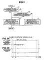
- step S1 a check is made to determine, based on input information from 4WD/DIFF ECU 22 regarding which state the transfer clutch 10 is in, whether a command signal generated from 4WD/DIFF ECU 22 for full engagement of transfer clutch 10 is present or absent.
- step S1 the routine proceeds from step S1 to step S3.
- step S1 the routine proceeds from step S1 to step S2.
- step S2 a check is made to determine, based on input information from 4WD/DIFF ECU 22 regarding which state the rear differential 4 is in, whether a command signal generated from 4WD/DIFF ECU 22 to differential limiting clutch 7 for full engagement of differential limiting clutch 7 (in other words, for the rear differential lock mode) is present or absent.
- YES negative
- step S2 the routine proceeds from step S2 to step S3.
- the main program is returned.
- VDC initiation threshold value ⁇ ( ⁇ ) suitable for the differential limited state is predetermined to be relatively lower than a normal VDC initiation threshold value ⁇ suitable for the differential non-limited state.
- step S4 normal VDC initiation threshold value ⁇ suitable for the differential non-limited state is set as the final VDC initiation threshold value.
- step S4 normal VDC initiation threshold value ⁇ suitable for the differential non-limited state is set as the final VDC initiation threshold value.
- VDC initiation threshold value ⁇ suitable for the differential non-limited state for example, when the vehicle understeer tendency starts to develop or when the vehicle oversteer tendency starts to develop, the VDC function is enabled and thus the vehicle dynamics control is initiated such that the actual yaw rate ⁇ is brought closer to the desired yaw rate ⁇ * by way of feedback control.
- a braking force applied to each road wheel is properly controlled.
- oversteer suppression control vehicle dynamics control executed under the vehicle oversteer condition in the 2WD mode
- a braking force needed for oversteer suppression control is applied to the front wheel of the faster-turning outer wheels.
- braking forces needed for oversteer suppression control may be applied to the respective faster-turning outer wheels.
- ⁇ n ⁇ - ⁇ *
- understeer suppression control vehicle dynamics control executed under the vehicle understeer condition in the 2WD mode
- a braking force needed for understeer suppression control is applied to the rear wheel of the slower-turning inner wheels.
- braking forces needed for understeer suppression control may be applied to the respective slower-turning inner wheels.
- normal VDC initiation threshold value ⁇ suited for the rear-wheel-drive state (2WD mode), in other words, the differential non-limited state, for the purpose of eliminating any unnatural feeling experienced by the driver, such as an unintended vehicle deceleration, which may occur owing to an undesirably advanced VDC initiation timing during cornering in the 2WD mode with the VDC control system conditioned in the operative state
- normal VDC initiation threshold value ⁇ contains a deadband to which the VDC control system will not effectively respond.
- normal VDC initiation threshold value ⁇ is predetermined to be relatively higher than VDC initiation threshold value ⁇ suitable for the differential limited state, for prevention of undesirable hunting.
- the relatively lower VDC initiation threshold valuer ⁇ ( ⁇ ) is set as the final VDC initiation threshold value, only in the differential limited state in which the differential motion between the front and rear wheel axles is limited with transfer clutch 10 engaged or the differential motion between the rear-left and rear-right wheel axles is limited with differential limiting clutch 7 engaged and thus there is an increased tendency for the controlled variable (actual yaw rate ⁇ ) to remarkably deviate from the desired value (desired yaw rate ⁇ *).
- VDC initiation threshold value ⁇ determined as the final VDC initiation threshold under the differential non-limited state
- VDC initiation threshold value ⁇ determined as the final VDC initiation threshold under the differential limited state
- the VDC routine of Fig. 2 flows from step S1 to step S3.
- the relatively lower VDC initiation threshold value ⁇ ( ⁇ ) suitable for the differential limited state is set as the final VDC initiation threshold value.
- VDC routine of Fig. 2 flows from step S1 via step S2 to step S3.
- VDC initiation threshold valuer ⁇ ( ⁇ ) suitable for the differential limited state is set as the final VDC initiation threshold value.
- VDC initiation threshold valuer ⁇ ( ⁇ ) that is suitable for the differential limited state and that vehicle dynamics control easily quickly comes into operation, in other words, in presence of a slight vehicle understeer tendency or a slight vehicle oversteer tendency
- the vehicle dynamics control can be quickly initiated in a manner so as to properly quickly adjust a braking force applied to each road wheel and to properly reduce the engine power output, and thus to bring the actual yaw rate ⁇ closer to the desired yaw rate ⁇ * by way of feedback control.
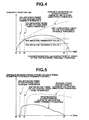
- the final VDC initiation threshold value is switched from normal VDC initiation threshold value ⁇ suitable for the differential non-limited state to VDC initiation threshold value ⁇ ( ⁇ ) suitable for the differential limited state at the time t0, and the final VDC initiation threshold value is switched from VDC initiation threshold value ⁇ ( ⁇ ) to normal VDC initiation threshold value ⁇ at the time t4.
- the final VDC initiation threshold value remains fixed permanently at normal VDC initiation threshold value ⁇ .
- VDC initiation threshold value which is switchable between the relatively higher VDC initiation threshold value ⁇ and the relatively lower VDC initiation threshold value ⁇ depending on whether the vehicle is in the differential non-limited state or in the differential limited state
- the VDC function is engaged at the time t1 to quickly initiate vehicle dynamics control.
- the vehicle dynamics control is initiated at the relatively earlier timing (at the time t1).
- yaw-rate deviation ⁇ n can rapidly converge to zero (see the falling curve indicated by the solid line in Fig. 4 at the time t3).
- the VDC function is engaged at the time t2. That is to say, owing to the relatively higher fixed VDC initiation threshold value ⁇ (> ⁇ ), the timing of initiation of vehicle dynamics control is somewhat retarded.
- the VDC system using the relatively higher fixed VDC initiation threshold value ⁇ cannot yet exhibit the tendency of convergence of yaw-rate deviation ⁇ n even after the time t3.
- the vehicle dynamics control terminates at a considerably later timing from the time t3.
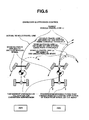
- the braking force characteristic curve indicated by the solid line in Fig. 5 As can be seen from the braking force characteristic curve indicated by the solid line in Fig. 5, according to the VDC system of the embodiment using the variable or switchable VDC initiation threshold value, by virtue of the vehicle dynamics control initiated at the relatively earlier timing t1, the braking force can be applied to the VDC controlled wheel, which is subjected to the vehicle dynamics control, at a relatively earlier timing.
- the level of the braking force applied for suppressing slight vehicle understeer or oversteer tendencies is still low.
- the braking force characteristic curve indicated by the solid line in Fig. 5 application of the relatively low braking force properly rapidly terminates at the same timing t3 when the vehicle dynamics control terminates.
- the braking force characteristic curve indicated by the broken line in Fig. 5 According to the VDC system using the fixed VDC initiation threshold value, owing to the vehicle dynamics control initiated at the relatively later timing t2 than the time t1, the braking force is applied to the VDC controlled wheel, which is subjected to the vehicle dynamics control, at a relatively later timing.
- the level of the braking force, applied for suppressing strong vehicle understeer or oversteer tendencies developing adequately is relatively high.
- the vehicle dynamics control tends to terminate at a considerably later timing from the time t3 and thus the braking force applied is maintained undesirably at a high level for a while even after the time t3
- VDC noncontrolled wheel Owing to the transferred braking force, a lateral grip force of each VDC noncontrolled wheel on the road tends to reduce, and therefore there is a possibility that the ability to stabilize dynamic vehicle behavior is undesirably lowered.
- the actual vehicle-travel line corresponds to the vehicle-travel line L C , which is obtained by the VDC system using the fixed VDC initiation threshold value and somewhat compensated for in the direction of oversteer suppression in comparison with the vehicle-travel line L N obtained in the VDC uncontrolled state in which the VDC function is disengaged.
- the actual vehicle-travel line corresponds to the vehicle-travel line L C , which is obtained by the VDC system using the fixed VDC initiation threshold value and somewhat compensated for in the direction of understeer suppression in comparison with the vehicle-travel line L N obtained in the VDC uncontrolled state in which the VDC function is disengaged.
- the magnitude of transferred braking force is substantially proportional to the magnitude of braking force applied to the VDC controlled wheel during vehicle dynamics control.
- the greater the magnitude of braking force applied to the VDC controlled wheel during vehicle dynamics control the greater the control interference between the VDC system and the differential limiting control system.
- the smaller the magnitude of braking force applied to the VDC controlled wheel during vehicle dynamics control the smaller the control interference.
- the vehicle dynamics control (oversteer suppression control) can be initiated at a relatively earlier timing at which the vehicle oversteer tendency does not yet sufficiently develop. Therefore, as can be seen from the right-hand half (oversteer suppression control in the 4WD mode) of Fig. 6, the braking force applied to the front-left wheel produces a relatively small yawing moment (a relatively small oversteer suppression moment) tending to rotate the vehicle about the center of gravity in the direction (counterclockwise when looking the plan view of Fig. 6) that the weak vehicle oversteer tendency is reduced and suppressed.
- the vehicle-travel line L I which is obtained by the VDC system using the variable or switchable VDC initiation threshold value determined based on whether the vehicle is in the differential limited state or in the differential non-limited state, becomes substantially identical to the target vehicle-travel line L T .
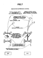
- the vehicle dynamics control (understeer suppression control) can be initiated at a relatively earlier timing at which the vehicle understeer tendency does not yet sufficiently develop. Therefore, as can be seen from the right-hand half (understeer suppression control in the 4WD mode) of Fig. 7, the braking force applied to the rear-right wheel produces a relatively small yawing moment (a relatively small understeer suppression moment) tending to rotate the vehicle about the center of gravity in the direction (clockwise when looking the plan view of Fig. 7) that the weak vehicle understeer tendency is reduced and suppressed.
- the vehicle-travel line L I which is obtained by the VDC system using the variable or switchable VDC initiation threshold value determined based on whether the vehicle is in the differential limited state or in the differential non-limited state, becomes substantially identical to the target vehicle-travel line L T .
- the vehicle dynamics control can be started at a relatively earlier timing by selecting the relatively lower VDC initiation threshold value ⁇ ( ⁇ ) instead of using the relatively higher VDC initiation threshold value ⁇ for the VDC system using the fixed VDC initiation threshold value. That is, by virtue of quick braking force control and quick engine power output control, both rapidly initiated due to the relatively lower VDC initiation threshold value ⁇ ( ⁇ ), the vehicle can be timely decelerated, thus enabling the grip force of each tire on the road to rapidly recover such that the actual vehicle cornering behavior can be properly quickly brought closer to the desired vehicle cornering behavior.
- Application of the relatively low braking force contributes to reduced control interference between vehicle dynamics control (oversteer or understeer suppression control) and differential limiting action.
- VDC apparatus of the embodiment using the variable or switchable VDC initiation threshold value ( ⁇ , ⁇ ), it is possible to enhance the ability to stabilize dynamic vehicle behavior (vehicle cornering behavior), while suppressing the control interference without lowering the vehicle dynamics control performance. That is, it is possible to optimize the vehicle dynamics control depending on whether the vehicle is in the differential limited state or in the differential non-limited state.
- VDC apparatus of the embodiment using the variable or switchable VDC initiation threshold value ( ⁇ , ⁇ ) and executing the VDC routine of Fig. 2, provides the following effects (1), (2), and (3).
- VDC apparatus of the embodiment for an automotive vehicle employing VDC ECU 23 that controls a braking force of at least one road wheel for the purpose of controlling vehicle cornering behavior (dynamic vehicle behavior) depending on the vehicle's turning conditions independently of the braking action of the driver, and a first differential limiting unit (first differential limiting means, e.g., transfer clutch 10) capable of limiting a differential motion between front and rear wheel axles and/or a second differential limiting unit (second differential limiting means, e.g., differential limiting clutch 7) capable of limiting a differential motion between left and right wheel axles, provided are (i) a first differential limiting state detection step S1 that detects or determines whether a front-and-rear wheel speed difference is limited or allowed, and (ii) a second differential limiting state detection step S2 that detects or determines whether a left-and-right wheel speed difference is limited or allowed.
- first differential limiting state detection step S1 that detects or determines whether a front-and-rear wheel speed difference is
- VDC ECU 23 Only when the first differential limiting state detection step S1 determines that the front-and-rear wheel speed difference is limited or the second differential limiting state detection step S2 determines that the left-and-right wheel speed difference is limited, VDC ECU 23 operates to advance the VDC initiation timing by selecting a lower one ⁇ ( ⁇ ) of the two different VDC initiation threshold values ⁇ and ⁇ .
- VDC ECU 23 uses the variable or switchable VDC initiation threshold value, it is possible to eliminate any unnatural feeling (e.g., an unintended vehicle deceleration) that the driver may experience during cornering in the differential non-limited state. Additionally, it is possible to effectively suppress or reduce the control interference between vehicle dynamics control and differential limiting action during cornering in the differential limited state. Furthermore, it is possible to enhance the ability to stabilize dynamic vehicle behavior during cornering in the differential limited state.
- VDC ECU 23 determines that the front-and-rear wheel speed difference is limited by means of the first differential limiting unit (e.g., transfer clutch 10) or the left-and-right wheel speed difference is limited by means of the second differential limiting unit (e.g., differential limiting clutch 7), VDC ECU 23 sets or changes the final VDC initiation threshold value to the relatively lower VDC initiation threshold value ⁇ ( ⁇ ) suitable for the differential limited state; so as to advance the VDC initiation timing. In this manner, according to the VDC apparatus of the embodiment, it is possible to easily effectively advance the VDC initiation timing by way of only a switching operation ( ⁇ ) of the final VDC initiation threshold value to the relatively lower VDC initiation threshold value ⁇ ( ⁇ ).
- VDC ECU 23 of the embodiment executing the routine of Fig. 2 uses a primary vehicle-dynamics-control initiation threshold value (i.e., a relatively higher VDC initiation threshold value ⁇ ) suitable for the differential non-limited state and a secondary vehicle-dynamics-control initiation threshold value (i.e., a relatively lower VDC initiation threshold value ⁇ ( ⁇ )) suitable for the differential limited state.
- VDC vehicle dynamics control
- transfer clutch 10 (1st differential limiting means) is comprised of a hydraulically-operated clutch or an electromagnetically-operated clutch whose engagement force is continuously variably controlled based on the front-and-rear wheel speed difference
- differential limiting clutch 7 (2nd differential limiting means) is also comprised of a hydraulically-operated clutch or an electromagnetically-operated clutch whose engagement force is continuously variably controlled based on the wheel speed difference between rear-left and rear-right wheels
- the final VDC initiation threshold value is continuously variably controlled responsively to the degree of limitation of the differential motion between front and rear wheel axles and/or the degree of limitation of the differential motion between left and right wheel axles.
- the modified routine shown in Fig. 8 is also executed as time-triggered interrupt routines to be triggered every predetermined sampling time intervals.
- step S21 a check is made to determine, based on input information from 4WD/DIFF ECU 22 regarding which state the transfer clutch 10 is in, whether a command signal generated from 4WD/DIFF ECU 22 for engagement of transfer clutch 10 is present or absent.
- YES negative
- step S21 the routine proceeds from step S21 to step S27.
- the processor of VDC ECU 23 estimates, based on the command signal value from the output interface of VDC ECU 23 to transfer clutch 10, an engagement force of transfer clutch 10.
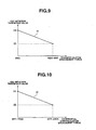
- the processor of VDC ECU 23 calculates or retrieves a first VDC initiation threshold value ⁇ 1 based on the estimated engagement force of transfer clutch 10 from the predetermined transfer-clutch engagement force versus 1st VDC initiation threshold value ⁇ 1 characteristic map shown in Fig. 9. Thereafter, the routine proceeds from step S22 to step S23. As seen from the predetermined transfer-clutch engagement force versus 1st VDC initiation threshold value ⁇ 1 characteristic map shown in Fig.
- the first VDC initiation threshold value ⁇ 1 is set to the maximum threshold value corresponding to normal VDC initiation threshold value ⁇ .
- the first VDC initiation threshold value ⁇ 1 is set to the minimum threshold value corresponding to VDC initiation threshold value ⁇ ( ⁇ ).
- the predetermined transfer-clutch engagement force versus 1st VDC initiation threshold value ⁇ 1 characteristic is obtained as a straight line interconnecting the point of the maximum threshold value (normal VDC initiation threshold value ⁇ ) in the 2WD mode and the point of the minimum threshold value (VDC initiation threshold value ⁇ ( ⁇ )) in the rigid 4WD mode.
- the predetermined transfer-clutch engagement force versus 1st VDC initiation threshold value ⁇ 1 characteristic is set as a linear characteristic that 1st VDC initiation threshold value ⁇ 1 reduces in a linear fashion, as the transfer-clutch engagement force increases.
- the predetermined transfer-clutch engagement force versus 1st VDC initiation threshold value ⁇ 1 characteristic may be set as a concave-up or concave-down curved characteristic that 1st VDC initiation threshold value ⁇ 1 reduces like a concave-up or concave-down quadratic curve, as the transfer-clutch engagement force increases.
- the predetermined transfer-clutch engagement force versus 1st VDC initiation threshold value ⁇ 1 characteristic may be set as a stepwise characteristic that 1st VDC initiation threshold value ⁇ 1 reduces in a stepwise manner, as the transfer-clutch engagement force increases.
- step S23 a check is made to determine, based on input information from 4WD/DIFF ECU 22 regarding which state the differential limiting clutch 7 is in, whether a command signal generated from 4WD/DIFF ECU 22 to differential limiting clutch 7 for engagement of differential limiting clutch 7 is present or absent.
- step S23 the routine proceeds from step S23 to step S24.
- step S23 is negative (NO)
- step S25 the routine proceeds from step S23 to step S25.
- step S24 the processor of VDC ECU 23 estimates, based on the command signal value from the output interface of VDC ECU 23 to differential limiting clutch 7, an engagement force of differential limiting clutch 7.
- the processor of VDC ECU 23 calculates or retrieves a second VDC initiation threshold value ⁇ 2 based on the estimated engagement force of differential limiting clutch 7 from the predetermined differential-limiting-clutch engagement force versus 2nd VDC initiation threshold value ⁇ 2 characteristic map shown in Fig. 10. Thereafter, the routine proceeds from step S24 to step S26. As seen from the predetermined differential-limiting-clutch engagement force versus 2nd VDC initiation threshold value ⁇ 2 characteristic map shown in Fig.
- the second VDC initiation threshold value ⁇ 2 is set to the maximum threshold value corresponding to normal VDC initiation threshold value ⁇ .
- the second VDC initiation threshold value ⁇ 2 is set to the minimum threshold value corresponding to VDC initiation threshold value ⁇ ( ⁇ ).
- the predetermined differential-limiting-clutch engagement force versus 2nd VDC initiation threshold value ⁇ 2 characteristic is obtained as a straight line interconnecting the point of the maximum threshold value (normal VDC initiation threshold value ⁇ ) in the differential free mode and the point of the minimum threshold value (VDC initiation threshold value ⁇ ( ⁇ )) in the differential lock mode.
- the predetermined differential-limiting-clutch engagement force versus 2nd VDC initiation threshold value ⁇ 2 characteristic is set as a linear characteristic that 2nd VDC initiation threshold value ⁇ 2 reduces in a linear fashion, as the differential-limiting-clutch engagement force increases.
- the predetermined differential-limiting-clutch engagement force versus 2nd VDC initiation threshold value ⁇ 2 characteristic may be set as a concave-up or concave-down curved characteristic that 2nd VDC initiation threshold value ⁇ 2 reduces in the form of a concave-up or concave-down quadratic curve, as the differential-limiting-clutch engagement force increases.
- the predetermined differential-limiting-clutch engagement force versus 2nd VDC initiation threshold value ⁇ 2 characteristic may be set as a stepwise characteristic that 2nd VDC initiation threshold value ⁇ 2 reduces in a stepwise manner, as the differential-limiting-clutch engagement force increases.
- the main program is returned.
- step S27 a check is made to determine, based on input information from 4WD/DIFF ECU 22 regarding which state the differential limiting clutch 7 is in, whether a command signal generated from 4WD/DIFF ECU 22 to differential limiting clutch 7 for engagement of differential limiting clutch 7 is present or absent.
- step S27 the routine proceeds from step S27 to step S28.
- step S27 is negative (NO)
- step S30 the routine proceeds from step S27 to step S30.
- step S28 in the same manner as step S24, the processor of VDC ECU 23 estimates, based on the command signal value from the output interface of VDC ECU 23 to differential limiting clutch 7, an engagement force of differential limiting clutch 7.
- the processor of VDC ECU 23 calculates or retrieves a second VDC initiation threshold value ⁇ 2 based on the estimated engagement force of differential limiting clutch 7 from the predetermined differential-limiting-clutch engagement force versus 2nd VDC initiation threshold value ⁇ 2 characteristic map shown in Fig. 10. Thereafter, the routine proceeds from step S28 to step S29.
- the maximum threshold value (normal VDC initiation threshold value ⁇ ) is set or determined as the final VDC initiation threshold value.
- step S30 normal VDC initiation threshold value ⁇ suitable for the differential non-limited state is set as the final VDC initiation threshold value.
- VDC initiation threshold value ⁇ is increasingly compensated for, so that vehicle dynamics control does not easily come into operation.
- VDC initiation threshold value ⁇ is decreasingly compensated for, so that vehicle dynamics control easily quickly comes into operation. Therefore, according to the VDC apparatus executing the modified VDC routine of Fig. 8, it is possible to greatly reconcile two requirements, that is, avoidance of control interference and enhanced vehicle dynamics control performance.
- VDC initiation threshold value ⁇ 1 adapted to enable the VDC function depending on the engagement force (the differential limiting degree) of the first differential unit (transfer clutch 10) and 2nd VDC initiation threshold value ⁇ 2 adapted to enable the VDC function depending on the engagement force (the differential limiting degree) of the second differential unit (differential limiting clutch 7) is set or determined as VDC initiation threshold value ⁇ .
- the VDC apparatus executing the modified VDC routine of Fig. 8 provides the following effects (4) and (5), in addition to the same effects (1) and (2) as the VDC apparatus executing the routine of Fig. 2.
- the differential limiting means (transfer clutch 10 and differential limiting clutch 7) is constructed as a variable differential limiting means capable of variably continuously adjusting the degree of limitation of the differential motion between front and rear wheel axles and/or the degree of limitation of the differential motion between left and right wheel axles, within a range from a differential non-limited state (a clutch disengaged state) via a differential partially-limited state (a clutch partially-engaged state) to a differential fully-limited state (a clutch fully-engaged state).
- VDC ECU 23 uses a preprogrammed clutch engagement force versus VDC initiation threshold value characteristic that a final VDC initiation threshold value continuously decreases from the maximum threshold value corresponding to normal VDC initiation threshold value ⁇ to the minimum threshold value corresponding to VDC initiation threshold value ⁇ ( ⁇ ), as a clutch engagement force increases.
- VDC initiation timing can be precisely determined. Therefore, according to the VDC apparatus executing the modified VDC routine of Fig.
- Transfer clutch 10 and differential limiting clutch 10 are used as the differential limiting means.
- transfer clutch 10 and differential limiting clutch 7 are used as the differential limiting means.
- VDC initiation threshold value ⁇ suitable for the differential limited state.
- an on-demand transfer clutch for example, a hydraulically-operated clutch or an electromagnetically-operated clutch whose engagement force is continuously variably controlled based on the front-and-rear wheel speed difference
- a front-and-rear wheel axle differential limiting means a front-and-rear wheel axle differential limiting means.
- another type of clutches such as a viscous coupling type transfer clutch, a dog clutch, a manually-operated center differential lock mechanism, and the like may be used as the front-and-rear wheel axle differential limiting means.
- all types of clutches through each of which a braking force created by vehicle dynamics control is transferred from a VDC controlled wheel to a first wheel axle of front and rear wheel axles, opposite to the second wheel axle associated with the VDC controlled wheel, can be classified as the front-and-rear wheel axle differential limiting means.
- an on-demand differential limiting clutch for example, a hydraulically-operated clutch or an electromagnetically-operated clutch whose engagement force is continuously variably controlled based on the left-and-right wheel speed difference, may be used.
- another type of clutches such as a viscous coupling type clutch, a dog clutch, a manually-operated differential lock mechanism, and the like may be used as the left-and-right wheel axle differential limiting means.
- a clutch engagement force is estimated based on a command signal value from the output interface of VDC ECU 23 to a differential limiting unit (transfer clutch 10 or differential limiting clutch 7).
- a differential limiting unit transfer clutch 10 or differential limiting clutch 7
- the differential limited or non-limited state may be estimated based on the wheel speed difference between road wheels whose differential motion is limited, the waveform of wheel speeds, or the frequencies of wheel speeds.
- the VDC apparatus of the invention is exemplified in an automotive vehicle employing a front-and-rear wheel differential limiting means (e.g., transfer clutch 10) and a left-and-right wheel differential limiting means (e.g., differential limiting clutch 7). It will be appreciated that the fundamental concept of the invention can also be applied to an automotive vehicle employing either one of a front-and-rear wheel differential limiting means (e.g., transfer clutch 10) and a left-and-right wheel differential limiting means (e.g., differential limiting clutch 7).
- a front-and-rear wheel differential limiting means e.g., transfer clutch 10
- a left-and-right wheel differential limiting means e.g., differential limiting clutch 7
- a VDC initiation threshold value itself is decreasingly compensated for or switched from a relatively higher threshold value ⁇ to a relatively lower threshold value ⁇ ( ⁇ ).
- At least one of factors calculating or deriving yaw-rate deviation ⁇ n may be properly compensated for in such a manner as to advance the VDC initiation timing in presence of a transition from the differential non-limited state to the differential limited state.
- the VDC initiation threshold value itself has to be fixed.
Landscapes
- Engineering & Computer Science (AREA)
- Transportation (AREA)
- Mechanical Engineering (AREA)
- Arrangement And Driving Of Transmission Devices (AREA)
- Control Of Driving Devices And Active Controlling Of Vehicle (AREA)
- Regulating Braking Force (AREA)
- Retarders (AREA)
Claims (10)
- Appareil de commande de dynamique de véhicule [VDC] pour un véhicule automobile muni d'un dispositif de limitation de différentiel (10, 7) permettant de limiter au moins un déplacement pris parmi un déplacement de différentiel entre des axes de roues avant et arrière et un déplacement de différentiel entre des axes de roues gauche et droite, comprenant:un système VDC (23) qui commande une force de freinage d'au moins une roue (8, 9, 15, 16) pour commander un comportement en virage de véhicule en fonction d'une condition de prise de virage de véhicule indépendamment d'une action de freinage de conducteur,caractérisé en ce que:le système VDC (23) fait avancer un cadencement d'initiation de VDC utilisé dans un état limité de différentiel où au moins un déplacement pris parmi le déplacement de différentiel d'axes de roues avant et arrière et le déplacement de différentiel d'axes de roues gauche et droite est limité, par comparaison avec un cadencement d'initiation de VDC utilisé dans un état non limité de différentiel, où le déplacement de différentiel d'axes de roues avant et arrière et le déplacement de différentiel d'axes de roues gauche et droite sont autorisés.
- Appareil VDC selon la revendication 1, dans lequel:le système VDC (23) fait avancer le cadencement d'initiation de VDC en modifiant une valeur de seuil d'initiation de VDC finale en une valeur de seuil d'initiation de VDC relativement plus faible (β) qu'une valeur de seuil d'initiation de VDC normale (α), qui est prédéterminée de manière à convenir pour l'état non limité de différentiel, en présence d'une transition depuis l'état non limité de différentiel jusqu'à l'état limité de différentiel.
- Appareil VDC selon la revendication 2, dans lequel:le système VDC (23) établit une valeur de seuil d'initiation de VDC primaire (α) correspondant à la valeur de seuil d'initiation de VDC normale en tant que valeur de seuil d'initiation de VDC finale dans l'état non limité de différentiel et établit une valeur de seuil d'initiation de VDC secondaire (β) correspondant à la valeur de seuil d'initiation de VDC relativement plus faible que la valeur de seuil d'initiation de VDC finale dans l'état limité de différentiel;le système VDC (23) initie la commande de dynamique de véhicule à un cadencement relativement plus tôt en réalisant une commutation depuis la valeur de seuil d'initiation de VDC primaire (α) jusqu'à la valeur de seuil d'initiation de VDC secondaire (β) en présence de la transition depuis l'état non limité de différentiel jusqu'à l'état limité de différentiel; etle système VDC (23) initie la commande de dynamique de véhicule à un cadencement relativement plus tard en réalisant une commutation depuis la valeur de seuil d'initiation de VDC secondaire (β) jusqu'à la valeur de seuil d'initiation de VDC primaire (α) en présence d'une transition depuis l'état limité de différentiel jusqu'à l'état non limité de différentiel.
- Appareil VDC selon la revendication 2, dans lequel:le dispositif de limitation de différentiel (10, 7) comprend un dispositif de limitation de différentiel variable permettant de régler en continu de façon variable un degré de limitation du déplacement de différentiel depuis l'état non limité de différentiel via un état partiellement limité de différentiel jusqu'à un état pleinement limité de différentiel;le système VDC détermine une valeur de seuil d'initiation de VDC (β1; β2) sur la base du degré de limitation du déplacement de différentiel à partir d'une caractéristique de valeur de seuil d'initiation de VDC prédéterminée de telle sorte que la valeur de seuil d'initiation de VDC (β1; β2) soit réduite lorsque le degré de limitation du déplacement de différentiel augmente, lorsque le véhicule est dans l'état partiellement limité de différentiel ou dans l'état pleinement limité de différentiel; etle système VDC détermine le cadencement d'initiation de VDC sur la base de la valeur de seuil d'initiation de VDC (β1; β2) calculée à partir de la caractéristique de valeur de seuil d'initiation de VDC prédéterminée lorsque le véhicule est dans l'état partiellement limité de différentiel ou dans l'état pleinement limité de différentiel.
- Appareil VDC selon la revendication 4, dans lequel:le dispositif de limitation de différentiel (10, 7) comprend une première unité de limitation de différentiel (10) permettant de limiter le déplacement de différentiel entre les axes de roues avant et arrière et une seconde unité de limitation de différentiel (7) permettant de limiter le déplacement de différentiel entre les axes de roues gauche et droite;le système VDC sélectionne celle plus faible d'une première valeur de seuil d'initiation de VDC (β1) déterminée sur la base du degré de limitation du déplacement de différentiel de la première unité de limitation de différentiel (10) et d'une seconde valeur de seuil d'initiation de VDC (β2) déterminée sur la base du degré de limitation du déplacement de différentiel de la seconde unité de limitation de différentiel (7) en tant que valeur de seuil d'initiation de VDC finale dans l'état limité de différentiel de la première unité de limitation de différentiel (10) et additionnellement dans l'état limité de différentiel de la seconde unité de limitation de différentiel (7); etle système VDC initie la commande de dynamique de véhicule à un cadencement qui est déterminé sur la base de la valeur de seuil d'initiation de VDC sélectionnée (β = min (β1, β2)).
- Procédé de commande d'un comportement en virage de véhicule d'un véhicule automobile muni d'un dispositif de limitation de différentiel (10, 7) permettant de limiter au moins un déplacement pris parmi un déplacement de différentiel entre les axes de roues avant et arrière et un déplacement de différentiel entre les axes de roues gauche et droite, le procédé comprenant:la commande d'une force de freinage d'au moins une roue (8, 9, 15, 16) afin d'exécuter une commande de dynamique de véhicule (VDC) au moyen de laquelle le comportement en virage de véhicule est commandé en fonction d'une condition de prise de virage de véhicule indépendamment d'une action de freinage de conducteur;la détection de si oui ou non le véhicule est dans un état limité de différentiel dans lequel au moins un déplacement pris parmi le déplacement de différentiel d'axes de roues avant et arrière et le déplacement de différentiel d'axes de roues gauche et droite est limité ou dans un état non limité de différentiel dans lequel le déplacement de différentiel d'axes de roues avant et arrière et le déplacement de différentiel d'axes de roues gauche et droite sont autorisés,caractérisé par:l'avancée d'un cadencement d'initiation de VDC utilisé dans l'état limité de différentiel par comparaison avec un cadencement d'initiation de VDC utilisé dans l'état non limité de différentiel.
- Procédé selon la revendication 6, dans lequel:le cadencement d'initiation de VDC est avancé en modifiant une valeur de seuil d'initiation de VDC finale depuis une valeur de seuil d'initiation de VDC normale (α) qui est prédéterminée de manière à convenir pour l'état non limité de différentiel jusqu'à une valeur de seuil d'initiation de VDC relativement plus faible (β) que la valeur de seuil d'initiation de VDC normale (α) en présence d'une transition depuis l'état non limité de différentiel jusqu'à l'état limité de différentiel.
- Procédé selon la revendication 7, comprenant en outre:l'établissement d'une valeur de seuil d'initiation de VDC primaire (α) correspondant à la valeur de seuil d'initiation de VDC normale en tant que valeur de seuil d'initiation de VDC finale dans l'état non limité de différentiel;l'établissement d'une valeur de seuil d'initiation VDC secondaire (β) correspondant à la valeur de seuil d'initiation de VDC relativement plus faible en tant que valeur de seuil d'initiation de VDC finale dans l'état limité de différentiel;l'initiation de la commande de dynamique de véhicule à un cadencement relativement plus tôt en réalisant une commutation depuis la valeur de seuil d'initiation de VDC primaire (α) jusqu'à la valeur de seuil d'initiation de VDC secondaire (β) en présence de la transition depuis l'état non limité de différentiel jusqu'à l'état limité de différentiel; etl'initiation de la commande de dynamique de véhicule à un cadencement relativement plus tard en réalisant une commutation depuis la valeur de seuil d'initiation de VDC secondaire (β) jusqu'à la valeur de seuil d'initiation de VDC primaire (α) en présence d'une transition depuis l'état limité de différentiel jusqu'à l'état non limité de différentiel.
- Procédé selon la revendication 7, dans lequel:le dispositif de limitation de différentiel (10, 7) comprend un dispositif de limitation de différentiel variable permettant de régler en continu de façon variable un degré de limitation du déplacement de différentiel depuis l'état non limité de différentiel via un état partiellement limité de différentiel jusqu'à un état pleinement limité de différentiel,le procédé comprenant en outre:la détermination d'une valeur de seuil d'initiation de VDC (β1 ; β2) sur la base du degré de limitation du déplacement de différentiel à partir d'une caractéristique de valeur de seuil d'initiation de VDC prédéterminée de telle sorte que la valeur de seuil d'initiation de VDC (β1 ; β2) soit réduite lorsque le degré de limitation du déplacement de différentiel augmente lorsque le véhicule est dans l'état partiellement limité de différentiel ou dans l'état pleinement limité de différentiel; etla détermination du cadencement d'initiation de VDC sur la base de la valeur de seuil d'initiation de VDC (β1 ; β2) calculée à partir de la caractéristique de valeur de seuil d'initiation de VDC prédéterminée lorsque le véhicule est dans l'état partiellement limité de différentiel ou dans l'état pleinement limité de différentiel.
- Procédé selon la revendication 9, dans lequel:le dispositif de limitation de différentiel (10, 7) comprend une première unité de limitation de différentiel (10) permettant de limiter le déplacement de différentiel entre les axes de roues avant et arrière et une seconde unité de limitation de différentiel (7) permettant de limiter le déplacement de différentiel entre les axes de roues gauche et droite,le procédé comprenant en outre:la détermination d'une première valeur de seuil d'initiation de VDC (β1) sur la base du degré de limitation du déplacement de différentiel de la première unité de limitation de différentiel (10);la détermination d'une seconde valeur de seuil d'initiation de VDC (β2) sur la base du degré de limitation du déplacement de différentiel de la seconde unité de limitation de différentiel (7);la sélection de celle plus faible des première et seconde valeurs de seuil d'initiation VDC (β1, β2) en tant que valeur de seuil d'initiation de VDC finale dans l'état limité de différentiel de la première unité de limitation de différentiel (10) et additionnellement dans l'état limité de différentiel de la seconde unité de limitation de différentiel (7); etl'initiation de la commande de dynamique de véhicule en un cadencement qui est déterminé sur la base de la valeur de seuil d'initiation de VDC sélectionnée (β = min (β1, β2)).
Applications Claiming Priority (2)
| Application Number | Priority Date | Filing Date | Title |
|---|---|---|---|
| JP2003125200A JP4258265B2 (ja) | 2003-04-30 | 2003-04-30 | 車両挙動制御装置 |
| JP2003125200 | 2003-04-30 |
Publications (3)
| Publication Number | Publication Date |
|---|---|
| EP1473204A2 EP1473204A2 (fr) | 2004-11-03 |
| EP1473204A3 EP1473204A3 (fr) | 2005-12-07 |
| EP1473204B1 true EP1473204B1 (fr) | 2007-03-14 |
Family
ID=32985582
Family Applications (1)
| Application Number | Title | Priority Date | Filing Date |
|---|---|---|---|
| EP04252467A Expired - Lifetime EP1473204B1 (fr) | 2003-04-30 | 2004-04-28 | Système de réglage de la dynamique de marche d'un véhicule |
Country Status (5)
| Country | Link |
|---|---|
| US (1) | US7693639B2 (fr) |
| EP (1) | EP1473204B1 (fr) |
| JP (1) | JP4258265B2 (fr) |
| CN (1) | CN1275814C (fr) |
| DE (1) | DE602004005258T2 (fr) |
Families Citing this family (49)
| Publication number | Priority date | Publication date | Assignee | Title |
|---|---|---|---|---|
| EP1478556B1 (fr) * | 2002-02-28 | 2006-05-24 | DaimlerChrysler AG | Dispositif et procede pour agir sur le mode de fonctionnement d'au moins un dispositif de stabilisation mis en place dans un vehicule |
| JP3870911B2 (ja) * | 2003-02-10 | 2007-01-24 | 日産自動車株式会社 | 車線逸脱防止装置 |
| JP2005271818A (ja) * | 2004-03-25 | 2005-10-06 | Mitsubishi Fuso Truck & Bus Corp | 車両のロールオーバ抑制制御装置 |
| DE102004029783A1 (de) * | 2004-06-21 | 2006-01-05 | Zf Friedrichshafen Ag | Vorrichtung und Verfahren zur Beeinflussung des Lenkverhaltens eines Kraftfahrzeugs |
| JP4293092B2 (ja) * | 2004-09-01 | 2009-07-08 | 株式会社アドヴィックス | 車両の運動制御装置 |
| SE0402539D0 (sv) * | 2004-10-21 | 2004-10-21 | Haldex Traction Ab | All wheel drive system |
| JP4704767B2 (ja) * | 2004-12-10 | 2011-06-22 | Gknドライブラインジャパン株式会社 | 車両駆動制御装置 |
| JP4721100B2 (ja) * | 2005-04-21 | 2011-07-13 | 株式会社アドヴィックス | 車両のローリング運動安定化制御装置 |
| US7890239B2 (en) * | 2005-10-13 | 2011-02-15 | Toyota Jidosha Kabushiki Kaisha | Vehicle suppressing OS or US by stagedly different devices |
| ES2362238T3 (es) | 2006-02-03 | 2011-06-30 | Eaton Corporation | Control de tracción y desviación lateral con estabilidad mejorada, utilizando un diferencial controlado eletrónicamente con deslizamiento limitado. |
| JP4877593B2 (ja) * | 2006-12-11 | 2012-02-15 | 富士重工業株式会社 | 車両制御装置 |
| JP4636012B2 (ja) * | 2006-12-11 | 2011-02-23 | トヨタ自動車株式会社 | 車両の制動制御装置 |
| JP4798012B2 (ja) * | 2007-01-30 | 2011-10-19 | トヨタ自動車株式会社 | 車両用差動制限装置の制御装置 |
| JP5261758B2 (ja) * | 2007-08-31 | 2013-08-14 | 本田技研工業株式会社 | 車両の自動変速制御装置 |
| US8589049B2 (en) | 2007-12-03 | 2013-11-19 | Lockheed Martin Corporation | GPS-based system and method for controlling vehicle characteristics based on terrain |
| US20090143937A1 (en) * | 2007-12-04 | 2009-06-04 | Lockheed Martin Corporation | GPS-based traction control system using wirelessly received weather data |
| US8145402B2 (en) | 2007-12-05 | 2012-03-27 | Lockheed Martin Corporation | GPS-based traction control system and method using data transmitted between vehicles |
| JP5130964B2 (ja) * | 2008-03-10 | 2013-01-30 | 日産自動車株式会社 | 車両の挙動制御装置 |
| US20100063701A1 (en) * | 2008-09-09 | 2010-03-11 | Lockheed Martin Corporation | Brake based viscous coupling alternative vehicle differential |
| DE102008055897A1 (de) * | 2008-11-05 | 2010-05-06 | Bayerische Motoren Werke Aktiengesellschaft | Steuersystem für ein zumindest zeitweise vierradgetriebenes Kraftfahrzeug |
| WO2010074226A1 (fr) * | 2008-12-26 | 2010-07-01 | 株式会社小松製作所 | Dispositif de contrôle de traction |
| US8352120B2 (en) | 2009-02-17 | 2013-01-08 | Lockheed Martin Corporation | System and method for stability control using GPS data |
| US8229639B2 (en) | 2009-02-17 | 2012-07-24 | Lockheed Martin Corporation | System and method for stability control |
| US8244442B2 (en) | 2009-02-17 | 2012-08-14 | Lockheed Martin Corporation | System and method for stability control of vehicle and trailer |
| JP2010247586A (ja) * | 2009-04-13 | 2010-11-04 | Yamaha Motor Co Ltd | 車両 |
| US8171791B2 (en) * | 2009-05-13 | 2012-05-08 | Robert Bosch Gmbh | Rotation sensor with onboard power generation |
| US8265842B2 (en) * | 2009-07-23 | 2012-09-11 | Ford Global Technologies, Llc | Electronic locking differential |
| JP5056822B2 (ja) * | 2009-09-24 | 2012-10-24 | トヨタ自動車株式会社 | 制動時姿勢変化低減構造 |
| JP5542014B2 (ja) * | 2010-09-10 | 2014-07-09 | 富士重工業株式会社 | 車両挙動制御装置 |
| CN103201149A (zh) * | 2010-11-04 | 2013-07-10 | 丰田自动车株式会社 | 制动控制装置 |
| DE102011010491A1 (de) * | 2011-02-07 | 2012-08-09 | Audi Ag | Verfahren und Steuerungsvorrichtung zum Aktivieren einer Fahrdynamikregelung, sowie Kraftwagen |
| US9169884B2 (en) | 2012-01-23 | 2015-10-27 | Caterpillar Inc. | Wet brake assembly |
| US8663058B2 (en) | 2012-01-23 | 2014-03-04 | Caterpillar Inc. | Brake assembly having piloted park brake housing |
| US8626410B2 (en) | 2012-01-23 | 2014-01-07 | Caterpillar Inc. | Powertrain system having lockable differential |
| KR101995074B1 (ko) * | 2012-08-10 | 2019-07-01 | 현대모비스 주식회사 | 차량의 선회 제어방법 및 차량용 선회 제어시스템 |
| JP5962470B2 (ja) * | 2012-11-30 | 2016-08-03 | トヨタ自動車株式会社 | 車両挙動制御装置 |
| CN103847741A (zh) * | 2012-12-04 | 2014-06-11 | 光阳工业股份有限公司 | 四轮车辆的车轮驱动控制系统及其车轮驱动控制方法 |
| US8918263B2 (en) | 2013-03-14 | 2014-12-23 | Clark Equipment Company | Traction control for power machine |
| JP6112303B2 (ja) * | 2013-10-31 | 2017-04-12 | マツダ株式会社 | 車両用挙動制御装置 |
| KR101724997B1 (ko) * | 2016-03-08 | 2017-04-18 | 현대자동차주식회사 | 차량의 카운터 스티어링 제어 방법 |
| US10029729B2 (en) * | 2016-03-15 | 2018-07-24 | GM Global Technology Operations LLC | Systems and methods for corner based reference command adjustment for chassis and active safety systems |
| JP6520890B2 (ja) * | 2016-11-02 | 2019-05-29 | トヨタ自動車株式会社 | 四輪駆動車の挙動制御装置 |
| JP6562008B2 (ja) * | 2017-02-01 | 2019-08-21 | トヨタ自動車株式会社 | 車線逸脱抑制装置 |
| JP6729441B2 (ja) | 2017-02-20 | 2020-07-22 | トヨタ自動車株式会社 | 四輪駆動車両の制御装置 |
| GB201720471D0 (en) * | 2017-12-08 | 2018-01-24 | Agco Int Gmbh | Utility vehicle braking |
| GB201720470D0 (en) * | 2017-12-08 | 2018-01-24 | Agco Int Gmbh | Utility vehicle braking |
| JP6977685B2 (ja) * | 2018-07-27 | 2021-12-08 | トヨタ自動車株式会社 | 四輪駆動車両の挙動制御装置 |
| KR102591992B1 (ko) * | 2018-09-11 | 2023-10-23 | 현대자동차주식회사 | 차량 및 그 제어방법 |
| CN110466604B (zh) * | 2019-08-29 | 2023-09-29 | 南京林业大学 | 轮毂电机驱动电动汽车差动驱动转向及稳定性的控制方法 |
Family Cites Families (9)
| Publication number | Priority date | Publication date | Assignee | Title |
|---|---|---|---|---|
| JP3372590B2 (ja) * | 1993-06-29 | 2003-02-04 | マツダ株式会社 | 車両の制御装置 |
| JPH1038067A (ja) * | 1996-07-18 | 1998-02-13 | Toyota Motor Corp | 車両の制御装置 |
| US6325469B1 (en) * | 1996-09-06 | 2001-12-04 | General Motors Corporation | Brake control system |
| JP2000344077A (ja) | 1999-06-08 | 2000-12-12 | Toyota Motor Corp | 車両の挙動制御装置 |
| JP3960740B2 (ja) | 2000-07-31 | 2007-08-15 | トヨタ自動車株式会社 | 車両の制動制御装置 |
| JP2002046509A (ja) * | 2000-08-03 | 2002-02-12 | Fuji Heavy Ind Ltd | 車両の運動制御装置 |
| US6595602B2 (en) * | 2001-06-05 | 2003-07-22 | Continental Teves, Inc. | Vehicle control of a locked drive system |
| EP1478556B1 (fr) * | 2002-02-28 | 2006-05-24 | DaimlerChrysler AG | Dispositif et procede pour agir sur le mode de fonctionnement d'au moins un dispositif de stabilisation mis en place dans un vehicule |
| DE60304388T2 (de) | 2002-05-22 | 2007-06-06 | Nissan Motor Co., Ltd., Yokohama | Fahrdynamik-Regelsystem für ein vierradgetriebenes Fahrzeug |
-
2003
- 2003-04-30 JP JP2003125200A patent/JP4258265B2/ja not_active Expired - Fee Related
-
2004
- 2004-04-28 EP EP04252467A patent/EP1473204B1/fr not_active Expired - Lifetime
- 2004-04-28 DE DE602004005258T patent/DE602004005258T2/de not_active Expired - Lifetime
- 2004-04-29 CN CNB2004100366584A patent/CN1275814C/zh not_active Expired - Fee Related
- 2004-04-29 US US10/834,373 patent/US7693639B2/en not_active Expired - Fee Related
Also Published As
| Publication number | Publication date |
|---|---|
| DE602004005258T2 (de) | 2007-11-22 |
| JP4258265B2 (ja) | 2009-04-30 |
| CN1541874A (zh) | 2004-11-03 |
| DE602004005258D1 (de) | 2007-04-26 |
| US7693639B2 (en) | 2010-04-06 |
| US20040267427A1 (en) | 2004-12-30 |
| CN1275814C (zh) | 2006-09-20 |
| EP1473204A3 (fr) | 2005-12-07 |
| EP1473204A2 (fr) | 2004-11-03 |
| JP2004330805A (ja) | 2004-11-25 |
Similar Documents
| Publication | Publication Date | Title |
|---|---|---|
| US7693639B2 (en) | Vehicle dynamics control apparatus | |
| US5701247A (en) | Integrated control system for 4WD vehicles for controlling driving torque distribution | |
| EP1270305B1 (fr) | Dispositif et méthode de commande de force d'entraínement pour véhicule à quatre roues motrices | |
| US7125086B2 (en) | Vehicle dynamics control system | |
| US5576959A (en) | Method for controlling yaw of a wheeled vehicle based on under-steer and over-steer containment routines | |
| EP0335335B1 (fr) | Commande de distribution du couple de rotation dans un véhicule à quatre roues motrices | |
| US5479348A (en) | Differential limiting torque control system for automotive vehicles | |
| US5471390A (en) | Differential limiting torque control system for automotive vehicles | |
| US7562948B2 (en) | Deceleration control apparatus and method for automotive vehicle | |
| US10392008B2 (en) | Control device for four-wheel drive vehicle | |
| US5379222A (en) | System for controlling the running state of a vehicle in accordance with a steering angle | |
| US5497333A (en) | Control system for integrally controlling operations of electronic torque split system and traction control system for automotive vehicle | |
| EP1400390A2 (fr) | Dispositif de commande de distribution de puissance pour véhicule à quatre roues motrices | |
| US20120083981A1 (en) | Vehicle running control apparatus | |
| EP3696040B1 (fr) | Procédé et dispositif de commande de véhicule | |
| EP1488974B1 (fr) | Système et procédé de commande d'entraînement pour detecter une instabilité d'un véhicule | |
| US10780779B2 (en) | Behavior control apparatus for a four-wheel drive vehicle | |
| JP3290539B2 (ja) | 車両のトラクションコントロール装置 | |
| JP2004017721A (ja) | 四輪駆動車の制御装置 | |
| US6212462B1 (en) | Automotive brake control system with skid control unit | |
| JP2917039B2 (ja) | 車両のスリップ制御装置 | |
| JPH0516780A (ja) | 車両のスリツプ制御装置 | |
| JPH0550912A (ja) | 車両のスリツプ制御装置 | |
| JP2898439B2 (ja) | 車両のスリップ制御装置 | |
| JP3016907B2 (ja) | 車両のスリップ制御装置 |
Legal Events
| Date | Code | Title | Description |
|---|---|---|---|
| PUAI | Public reference made under article 153(3) epc to a published international application that has entered the european phase |
Free format text: ORIGINAL CODE: 0009012 |
|
| 17P | Request for examination filed |
Effective date: 20040513 |
|
| AK | Designated contracting states |
Kind code of ref document: A2 Designated state(s): AT BE BG CH CY CZ DE DK EE ES FI FR GB GR HU IE IT LI LU MC NL PL PT RO SE SI SK TR |
|
| AX | Request for extension of the european patent |
Extension state: AL HR LT LV MK |
|
| PUAL | Search report despatched |
Free format text: ORIGINAL CODE: 0009013 |
|
| AK | Designated contracting states |
Kind code of ref document: A3 Designated state(s): AT BE BG CH CY CZ DE DK EE ES FI FR GB GR HU IE IT LI LU MC NL PL PT RO SE SI SK TR |
|
| AX | Request for extension of the european patent |
Extension state: AL HR LT LV MK |
|
| AKX | Designation fees paid |
Designated state(s): DE FR GB |
|
| GRAP | Despatch of communication of intention to grant a patent |
Free format text: ORIGINAL CODE: EPIDOSNIGR1 |
|
| RIN1 | Information on inventor provided before grant (corrected) |
Inventor name: TANAKA, NOBUYUKI Inventor name: SUZUKI, HIDETOSHI |
|
| GRAS | Grant fee paid |
Free format text: ORIGINAL CODE: EPIDOSNIGR3 |
|
| GRAA | (expected) grant |
Free format text: ORIGINAL CODE: 0009210 |
|
| RIN1 | Information on inventor provided before grant (corrected) |
Inventor name: TANAKA, NOBUYUKI Inventor name: SUZUKI, HIDETOSHI |
|
| AK | Designated contracting states |
Kind code of ref document: B1 Designated state(s): DE FR GB |
|
| REG | Reference to a national code |
Ref country code: GB Ref legal event code: FG4D |
|
| REF | Corresponds to: |
Ref document number: 602004005258 Country of ref document: DE Date of ref document: 20070426 Kind code of ref document: P |
|
| ET | Fr: translation filed | ||
| PLBE | No opposition filed within time limit |
Free format text: ORIGINAL CODE: 0009261 |
|
| STAA | Information on the status of an ep patent application or granted ep patent |
Free format text: STATUS: NO OPPOSITION FILED WITHIN TIME LIMIT |
|
| 26N | No opposition filed |
Effective date: 20071217 |
|
| PGFP | Annual fee paid to national office [announced via postgrant information from national office to epo] |
Ref country code: GB Payment date: 20140423 Year of fee payment: 11 |
|
| PGFP | Annual fee paid to national office [announced via postgrant information from national office to epo] |
Ref country code: FR Payment date: 20140409 Year of fee payment: 11 Ref country code: DE Payment date: 20140430 Year of fee payment: 11 |
|
| REG | Reference to a national code |
Ref country code: DE Ref legal event code: R119 Ref document number: 602004005258 Country of ref document: DE |
|
| GBPC | Gb: european patent ceased through non-payment of renewal fee |
Effective date: 20150428 |
|
| PG25 | Lapsed in a contracting state [announced via postgrant information from national office to epo] |
Ref country code: GB Free format text: LAPSE BECAUSE OF NON-PAYMENT OF DUE FEES Effective date: 20150428 Ref country code: DE Free format text: LAPSE BECAUSE OF NON-PAYMENT OF DUE FEES Effective date: 20151103 |
|
| REG | Reference to a national code |
Ref country code: FR Ref legal event code: ST Effective date: 20151231 |
|
| PG25 | Lapsed in a contracting state [announced via postgrant information from national office to epo] |
Ref country code: FR Free format text: LAPSE BECAUSE OF NON-PAYMENT OF DUE FEES Effective date: 20150430 |