EP1473431A1 - Dispositif ferme-porte de secours avec ouverture libre en opération normale - Google Patents
Dispositif ferme-porte de secours avec ouverture libre en opération normale Download PDFInfo
- Publication number
- EP1473431A1 EP1473431A1 EP03008858A EP03008858A EP1473431A1 EP 1473431 A1 EP1473431 A1 EP 1473431A1 EP 03008858 A EP03008858 A EP 03008858A EP 03008858 A EP03008858 A EP 03008858A EP 1473431 A1 EP1473431 A1 EP 1473431A1
- Authority
- EP
- European Patent Office
- Prior art keywords
- door
- locking
- closing
- door closer
- closer
- Prior art date
- Legal status (The legal status is an assumption and is not a legal conclusion. Google has not performed a legal analysis and makes no representation as to the accuracy of the status listed.)
- Withdrawn
Links
- 230000007246 mechanism Effects 0.000 claims abstract description 70
- 238000000034 method Methods 0.000 claims description 23
- 230000033001 locomotion Effects 0.000 claims description 8
- 238000009434 installation Methods 0.000 claims description 6
- 230000005540 biological transmission Effects 0.000 claims description 4
- 230000005291 magnetic effect Effects 0.000 claims description 4
- 239000007787 solid Substances 0.000 claims description 2
- 238000012546 transfer Methods 0.000 claims description 2
- 230000001960 triggered effect Effects 0.000 abstract 1
- 230000008901 benefit Effects 0.000 description 3
- 230000008569 process Effects 0.000 description 3
- 230000032683 aging Effects 0.000 description 2
- 238000013461 design Methods 0.000 description 2
- 238000001514 detection method Methods 0.000 description 2
- 239000000463 material Substances 0.000 description 2
- 239000000779 smoke Substances 0.000 description 2
- 238000010521 absorption reaction Methods 0.000 description 1
- 238000000418 atomic force spectrum Methods 0.000 description 1
- 238000010276 construction Methods 0.000 description 1
- 230000008878 coupling Effects 0.000 description 1
- 238000010168 coupling process Methods 0.000 description 1
- 238000005859 coupling reaction Methods 0.000 description 1
- 238000013016 damping Methods 0.000 description 1
- 230000001419 dependent effect Effects 0.000 description 1
- 230000005611 electricity Effects 0.000 description 1
- 238000005516 engineering process Methods 0.000 description 1
- 230000005294 ferromagnetic effect Effects 0.000 description 1
- 230000003993 interaction Effects 0.000 description 1
- 230000007774 longterm Effects 0.000 description 1
- 238000012423 maintenance Methods 0.000 description 1
- 239000011505 plaster Substances 0.000 description 1
- 230000003449 preventive effect Effects 0.000 description 1
- 230000009467 reduction Effects 0.000 description 1
- 238000012360 testing method Methods 0.000 description 1
Images





Classifications
-
- E—FIXED CONSTRUCTIONS
- E05—LOCKS; KEYS; WINDOW OR DOOR FITTINGS; SAFES
- E05F—DEVICES FOR MOVING WINGS INTO OPEN OR CLOSED POSITION; CHECKS FOR WINGS; WING FITTINGS NOT OTHERWISE PROVIDED FOR, CONCERNED WITH THE FUNCTIONING OF THE WING
- E05F1/00—Closers or openers for wings, not otherwise provided for in this subclass
- E05F1/002—Closers or openers for wings, not otherwise provided for in this subclass controlled by automatically acting means
- E05F1/006—Closers or openers for wings, not otherwise provided for in this subclass controlled by automatically acting means by emergency conditions, e.g. fire
-
- E—FIXED CONSTRUCTIONS
- E05—LOCKS; KEYS; WINDOW OR DOOR FITTINGS; SAFES
- E05F—DEVICES FOR MOVING WINGS INTO OPEN OR CLOSED POSITION; CHECKS FOR WINGS; WING FITTINGS NOT OTHERWISE PROVIDED FOR, CONCERNED WITH THE FUNCTIONING OF THE WING
- E05F3/00—Closers or openers with braking devices, e.g. checks; Construction of pneumatic or liquid braking devices
- E05F3/22—Additional arrangements for closers, e.g. for holding the wing in opened or other position
- E05F3/221—Mechanical power-locks, e.g. for holding the wing open or for free-moving zones
- E05F3/222—Mechanical power-locks, e.g. for holding the wing open or for free-moving zones electrically operated
-
- E—FIXED CONSTRUCTIONS
- E05—LOCKS; KEYS; WINDOW OR DOOR FITTINGS; SAFES
- E05Y—INDEXING SCHEME ASSOCIATED WITH SUBCLASSES E05D AND E05F, RELATING TO CONSTRUCTION ELEMENTS, ELECTRIC CONTROL, POWER SUPPLY, POWER SIGNAL OR TRANSMISSION, USER INTERFACES, MOUNTING OR COUPLING, DETAILS, ACCESSORIES, AUXILIARY OPERATIONS NOT OTHERWISE PROVIDED FOR, APPLICATION THEREOF
- E05Y2201/00—Constructional elements; Accessories therefor
- E05Y2201/40—Motors; Magnets; Springs; Weights; Accessories therefor
- E05Y2201/46—Magnets
- E05Y2201/462—Electromagnets
-
- E—FIXED CONSTRUCTIONS
- E05—LOCKS; KEYS; WINDOW OR DOOR FITTINGS; SAFES
- E05Y—INDEXING SCHEME ASSOCIATED WITH SUBCLASSES E05D AND E05F, RELATING TO CONSTRUCTION ELEMENTS, ELECTRIC CONTROL, POWER SUPPLY, POWER SIGNAL OR TRANSMISSION, USER INTERFACES, MOUNTING OR COUPLING, DETAILS, ACCESSORIES, AUXILIARY OPERATIONS NOT OTHERWISE PROVIDED FOR, APPLICATION THEREOF
- E05Y2201/00—Constructional elements; Accessories therefor
- E05Y2201/40—Motors; Magnets; Springs; Weights; Accessories therefor
- E05Y2201/47—Springs
- E05Y2201/474—Compression springs
-
- E—FIXED CONSTRUCTIONS
- E05—LOCKS; KEYS; WINDOW OR DOOR FITTINGS; SAFES
- E05Y—INDEXING SCHEME ASSOCIATED WITH SUBCLASSES E05D AND E05F, RELATING TO CONSTRUCTION ELEMENTS, ELECTRIC CONTROL, POWER SUPPLY, POWER SIGNAL OR TRANSMISSION, USER INTERFACES, MOUNTING OR COUPLING, DETAILS, ACCESSORIES, AUXILIARY OPERATIONS NOT OTHERWISE PROVIDED FOR, APPLICATION THEREOF
- E05Y2900/00—Application of doors, windows, wings or fittings thereof
- E05Y2900/10—Application of doors, windows, wings or fittings thereof for buildings or parts thereof
- E05Y2900/13—Type of wing
- E05Y2900/132—Doors
Definitions
- the present invention relates to a method to ensure automatic closing a building door in the event of a fire alarm, a free-wheeling door closer and a freewheel door locking device for Implementation of the process and kits for forming the Free-running door locking device according to the generic terms of the independent claims.
- Automatic closing of doors at Fire is particularly required where the building doors in addition to their normal function, additional functions in preventive fire protection, for example a fire spread as fire doors or the entry of smoke into certain areas of the building should prevent and / or certain pressure and flow conditions in a building in the event of a fire should.
- Such so-called free-wheel door closers are for example from GEZE GmbH, DE-71226 Leonberg, under the product names TS 5000 EFS and TS 5000 RFS or from DORMA GmbH + Co. KG, DE-58256 Ennepetal, under the product names TS 73 FLT and TS 99 FL available.
- a first aspect of the invention relates to a Procedure for ensuring automatic closing a building door in the event of a fire alarm.
- a Door closer with a spring-operated locking mechanism and preferably with hydraulic movement damping like that between the door to be closed and a solid physicality, e.g. a wall or a column firmly attached to the floor, that an automatic closing of the door the door closer in the absence of a closing force counteracting force of the locking mechanism, such as by an operator or a locking mechanism can be applied, is ensured. Then the door is opened against that of Closing mechanism of the door closer generated Closing force opened, the springs of the locking mechanism are increasingly biased.
- the locking mechanism is then positioned electrically activated and de-energized inactive locking devices such as. Magnetic holder or electrically operated Bolt purely mechanically by positive and / or non-positive connection determined, which causes the closing function of the door closer is temporarily deactivated.
- the locking device are de-energized in the event of a fire alarm electrical supply line with electrical Electricity supplied.
- the door closer also becomes like this between the door and the fixed physicality arranged, e.g. by only in the closing direction force-transmitting coupling to the door or to the Physicality, or within its locking mechanism designed in this way, e.g. with a one-way clutch between the locking mechanism and an actuating element, that the door with the locking mechanism locked between a fully closed position and the limited by the determined door closer open Position is free to move (freewheel function).
- the locking mechanism by directly or indirectly holding on to the automatic closing of the door the closing force the door-transmitting component in the with the door open accomplished by this component.
- this will be the closing force on the door closer transmitting part of the door closer connected to the door in such a way that it only transfer the closing forces in the closing direction can and at least in the opposite direction locked locking mechanism decoupled in terms of movement or can be decoupled.
- the closing force on the Door-transmitting component of the door closer is non-positive connected to the door against the closing force direction, which is preferably a mechanical snap or a magnetic catch, the door can for free running with little effort from the door closer be decoupled or locked on the door closer so that they are also permanent during normal operation can be fully open.
- the closing force direction which is preferably a mechanical snap or a magnetic catch
- locking lever or closing arm formed around an essentially and preferably parallel to the door pivot axis with this aligned swivel axis fixed to the building is pivotable.
- the difference between locking lever and locking arm consists essentially in that the locking lever is carried by the locking mechanism of the door closer while the locking arm is directly on a building-fixed Physicality is fixed.
- building-fixed locking means takes place, such as Electromagnets or electrically activated non-positive and / or positive holders, which is advantageous in the range of its pivot axis distal end of the locking lever or Closing arm takes place, because this is relatively small Holding forces result in what, at least in the case of non-positive Detection using electromagnets, the advantage of a results in low energy requirements.
- a Lock arm which uses the locking mechanism the door closer carries and preferably in itself receives.
- the door closer carries and preferably in itself receives.
- the procedure is a second door closer between the door and a fixed physicality which for the permanent automatic closing of the Door serves.
- a closing force is permanent made available, which in the event of an alarm Closing force of the door closer normally found is supplemented so that it also opens up to the outside Main entrance doors of stairwells of high-rise buildings, which in case of fire with blowers under excess pressure be placed to prevent smoke from entering it, can be safely closed at any time.
- a Door closer with locking lever used, whose Closing lever either at its non-driven end interacts with a slide rail or there over a Joint with an additional linkage to form a scissor linkage connected is.
- a second aspect of the invention relates a freewheel door closer to implement the process according to the first aspect.
- the door closer includes a spring-operated locking mechanism, which via a one-way clutch with a locking lever is coupled and in a biased, at Intended installation of an open door position corresponding position with internal, electrically activated and detachable inactive locking devices is to temporarily deactivate the Lock function of the door closer.
- the locking device are designed in such a way that they are mechanical Determination of the preloaded locking mechanism by Positive and / or non-hydraulic connection cause. Suitable means with which great prestressing forces mechanically with small control forces are checked by the specialist on the Known in the field of mechanics and are therefore not here spelled out in more detail.
- Such a freewheel door closer can be assembled in the usual way and avoids the Disadvantages of today's known freewheel door closers such as Aging, springback and "creeping in" of the free Opening angle of the free-running door.
- this includes a slide rail for Guidance of the locking lever or a scissors linkage, which includes the locking lever.
- a third aspect of the invention relates a freewheel door locking device for performing the Procedure according to the first aspect.
- the freewheel door locking device includes a door closer with spring-operated locking mechanism, one Locking lever, which with the locking mechanism of the Door closer is coupled, and external, i.e. Not in Locking mechanism housing of the locking mechanism, which can be activated by electrical current and are inactive when de-energized.
- the locking means and the door closer is designed such that the locking means in the activated state are able to provided for transferring the closing force to the door Door closer component, e.g. the locking lever or a housing containing the locking mechanism, directly, or indirectly through physicalities associated with them, against the closing force of the locking mechanism positively and / or non-positively in a desired Hold position.
- Such a freewheel door locking device can be used in a cost-effective manner with commercially available Door closers are formed and avoids the Disadvantages of today's known freewheel door closers such as Running noise, aging, springback and "creeping in” the free opening angle of the free-running door.
- the locking means at least one electromagnet, the interacts with a suitable ferromagnetic holding surface, which are preferably movable on the to be held Component is attached so that it has a certain Has angular tolerance.
- a suitable ferromagnetic holding surface which are preferably movable on the to be held Component is attached so that it has a certain Has angular tolerance.
- the is advantageous Electromagnet also designed so that it is on simple way, e.g. using screws and dowels can be attached to a wall.
- Such electromagnets with associated holding elements forming a holding surface are commercially available and are already being used for Emergency locking systems for normally open ones Doors used so that on expensive tests and lengthy approval procedures can be dispensed with.
- the freewheel door locking device is for transmission the closing force on the door component the locking lever, this preferably on its non-driven end has a holding surface for an electromagnet or other holding device for Interaction with other suitable locking devices having.
- Such a construction is particularly simple and inexpensive free-running door locking devices.
- the locking lever preferably also has in the area of its free, non-driven end a roller on which to transmit the closing force serves on the door in such a way that the roller at Closing presses on the outer surface of the door leaf rolls there if necessary. This makes it possible the door closer with the axis of rotation of the locking lever to be installed offset to the swivel axis of the door without a loss of closing force due to friction between Closing lever and door when closing.
- the door closer is attached to a supporting body, which is preferably designed as a closing arm is a hinge at one of its two ends has pivotable for attachment around a substantially vertical axis around a building-fixed physicality.
- the support body is intended for transferring the closing forces to the door Component.
- the free-running door locking device includes the door closer a slide rail for guiding the locking lever or is the locking lever part of a Scissors linkage.
- a fourth aspect of the invention relates a material kit with a locking lever and one Electromagnet, with which by combination with a door closing mechanism, which for locking lever with Slide rail or locking lever for scissor linkage is provided a free-wheel door locking device can be formed according to the third aspect.
- the Locking lever is designed for mounting on the door locking mechanism and points in the area of that In the end, not for mounting on the door locking mechanism is provided, that is in the area of the non-driven In the end, a holding surface for the electromagnet on and preferably an additional roller for transmission the closing force on the door.
- the electromagnet is designed such that it can easily can be mounted on a wall. With such a kit can easily lock existing door locking systems to be converted to one according to the invention.
- a fifth aspect of the invention relates a material kit with a locking arm for carrying one Locking mechanism and with an electromagnet, with by combining it with a door locking mechanism with locking lever and slide rail or with a door locking mechanism with a locking lever Scissor linkage also a free-wheel door locking device according to the third aspect of Invention can be formed.
- the locking arm which for Wear and preferably for full absorption the locking mechanism and to transmit the locking force serves on the door, has a hinge element at one end to swivel to fix it a substantially vertical axis around a wall and points in the area of its other hinge-free end a holding surface for the electromagnet.
- the electromagnet is designed for wall mounting.
- FIG. 1 The basic principle of a preferred embodiment the invention is apparent from Fig. 1, in which the Installation situation of a building door 1 with one according to the invention Freewheel door locking device in the closed Detail of the alarm state is shown. How to recognize there is the freewheel door locking device shown here from one on the wall 4 above the door 1 fastened door closer 2, with a spring operated Locking mechanism 3 and one driven by it Closing lever 6, and from an electromagnet 5, which is attached to the wall 4 next to the door 1.
- the Electromagnet 5 is designed such that it is in the Is able to switch on after a fully open door 1 against that of the locking mechanism 3 generated the closing lever 6 on the holding surface 8 arranged thereon in the complete hold open position and so the Deactivate the closing function of the door closer 2, as long as the power supply is maintained.
- There the closing lever 6 only in the closing direction Lying on the outer surface of the door with the Door 1 is connected and otherwise no connection with door 1, door 1 and locking lever 6 are exclusive Connected to movement in the closing force direction and otherwise decoupled from each other. This leads to, that the door 1 as soon as the locking lever 6 with the holding surface 8 held non-positively on the electromagnet 5 is freely movable between the completely closed Position and that held by the Closing lever 6 limited fully open position.
- Fig. 2 shows a situation as in Fig. 1 with another free-running door locking device, which differs essentially from that shown in Fig. 1 differs that the closing lever 6 next to the holding surface 8 an additional roller at its free end 10, which has the form fit in the closing force direction between locking lever 6 and door 1.
- the closing lever 6 next to the holding surface 8 an additional roller at its free end 10, which has the form fit in the closing force direction between locking lever 6 and door 1.
- the roller 10 At the automatic closing of door 1 with the locking device rolls the roller 10 on the door leaf surface since the pivot axes of door 1 and the locking lever 6, in contrast to that shown in Fig. 1 Locking device, in this case are not identical. Because the pivot axis of the locking lever 6 in the pivoting range the door 1 is there is also a collision to avoid the locking lever 6 with the door 1 Closing mechanism 3 arranged higher than in Fig. 1, such that the closing lever 6 above the door 1 comes to lie.
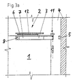
- FIGS 3a and 3b also show sections the installation situation when the alarm is closed a building door 1 with another according to the invention Freewheel door locking device, whereby in 3b shows the arrangement of the door locking device Normal situation and closed door 1 dashed is shown.
- this is here shown freewheel door locking device from a door closer 2 with a spring-operated locking mechanism 3, which is arranged in a locking arm 7 pivotable about a hinge 11 on the door 1 receiving Wall 4 is attached, and one of the locking mechanism 3 driven locking lever 6, which on his non-driven end in a slide rail 12 which is attached to the wall 4 above the door 1, is guided, and from an electromagnet 5, which is next to the wall 4 the door 1 is attached and is able to with the on Supply current after fully opening the door 1 against that of the locking mechanism 3 generated closing force the locking arm 7 with the Closing mechanism 3 on the holding surface 8 in the complete hold open position and so the Deactivate the closing function of the door closer 2, as long as the electromagnet 5 is supplied with current.
- the holding surface 8 is released from the electromagnet 5 and the closing arm 7 is from Locking mechanism 3 with door 1, if provided it is not already closed, in the closing direction moves until its movement through the fully closed Door 1 or by an attacking on door 1, the counteracting force, stopped becomes.
- the pivot axis of the locking arm 7 is identical here with that of door 1 so that when it closes the door 1 with the door closer 2 for no relative movement and therefore no friction loss between Lock arm 7 and door 1 comes.
- FIG. 3c shows an illustration like FIG. 3b with the only difference that here instead of the combination Locking lever 6 and slide rail 12 a one Locking lever 6 including scissors linkage 19 for Use comes, which leads to cost advantages an optimized closing force curve over the door opening angle seen leads.
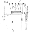
- Fig. 4 shows a situation as in Fig. 3a with another free-wheel door locking device, which differs from that shown in FIGS. 3a and 3b differs essentially in that the closing arm 7 is arranged above the door 1 and the door 1 above closes a driver 13 belonging to this.
- a door locking device can be Ensure maximum opening angle of door 1 as the Driver 13 can be made significantly flatter than the locking mechanism 3 accommodating itself Lock arm 7.
- FIG 5 shows a situation similar to that in FIG Fig. 4, but with the difference that here the slide rail 12 and the locking lever 6 of the freewheel door locking device arranged below the locking arm 7 is and an additional door closer on door 1 9 is arranged, the locking lever 6 in one also attached to the wall 4 above the door 1 another slide rail 12 is guided.
- This additional door closer 9 cannot be deactivated, so that the door 1 during normal operation through this is automatically closed and shown in the Alarm situation additionally through the locking mechanism 3 the freewheel door locking device is closed, see above that significantly increased compared to normal operation Closing force results.
- the shown in Figures 3 to 5 Embodiments can also be designed in this way be that the pivot axis of the locking arm 7 is not is identical to the pivot axis of door 1. In one in such a case it is advantageous if the closing force transmission to door 1 via one on the outside door surface rollable component takes place, e.g. by the in the Figures 4 and 5 shown driver 13 as roles are trained.
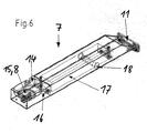
- the Lock arm 7 has a hinge 11 at one end, with which it can be attached to a wall, that it can be swiveled around a vertical axis.
- the opening 14 is dimensioned such that the electromagnet 5 for contacting the holding surface 8 in the opening 14 can dip and any plaster laid supply lines through cutouts on the side 16 can be performed.
- the locking arm 7 has a space 17 for receiving the Door closing mechanism 3, which with outlet openings 18 is equipped for the locking lever drive.
Landscapes
- Engineering & Computer Science (AREA)
- Mechanical Engineering (AREA)
- Business, Economics & Management (AREA)
- Emergency Management (AREA)
- Special Wing (AREA)
Priority Applications (1)
| Application Number | Priority Date | Filing Date | Title |
|---|---|---|---|
| EP03008858A EP1473431A1 (fr) | 2003-04-28 | 2003-04-28 | Dispositif ferme-porte de secours avec ouverture libre en opération normale |
Applications Claiming Priority (1)
| Application Number | Priority Date | Filing Date | Title |
|---|---|---|---|
| EP03008858A EP1473431A1 (fr) | 2003-04-28 | 2003-04-28 | Dispositif ferme-porte de secours avec ouverture libre en opération normale |
Publications (1)
| Publication Number | Publication Date |
|---|---|
| EP1473431A1 true EP1473431A1 (fr) | 2004-11-03 |
Family
ID=32981745
Family Applications (1)
| Application Number | Title | Priority Date | Filing Date |
|---|---|---|---|
| EP03008858A Withdrawn EP1473431A1 (fr) | 2003-04-28 | 2003-04-28 | Dispositif ferme-porte de secours avec ouverture libre en opération normale |
Country Status (1)
| Country | Link |
|---|---|
| EP (1) | EP1473431A1 (fr) |
Cited By (7)
| Publication number | Priority date | Publication date | Assignee | Title |
|---|---|---|---|---|
| CN105442978A (zh) * | 2015-12-16 | 2016-03-30 | 瓯宝安防科技股份有限公司 | 闭门器电磁释放滑轨摇臂 |
| DE102015000612A1 (de) | 2015-01-16 | 2016-07-21 | Assa Abloy Sicherheitstechnik Gmbh | Sicherungsvorrichtung zur Sicherung einer Tür in Flucht- und Rettungswagen |
| CN106193873A (zh) * | 2016-07-29 | 2016-12-07 | 广西安讯科技投资有限公司 | 消防泵房闭门器的安装方法 |
| CN106223762A (zh) * | 2016-07-29 | 2016-12-14 | 广西安讯科技投资有限公司 | 图书馆闭门器的安装方法 |
| CN113309441A (zh) * | 2021-07-07 | 2021-08-27 | 乐辉 | 一种实时延时定位的联动闭门器机构 |
| SE2150100A1 (en) * | 2021-01-28 | 2022-07-29 | Assa Abloy Ab | Brake device, arrangement for controlling movements of access member, and access member system |
| DE102022209690A1 (de) * | 2022-09-15 | 2024-03-21 | Geze Gmbh | Türschließer mit Freilauffunktion |
Citations (2)
| Publication number | Priority date | Publication date | Assignee | Title |
|---|---|---|---|---|
| US4161804A (en) * | 1977-12-21 | 1979-07-24 | Rixson-Firemark, Inc. | Heat-actuated door latch |
| EP0985794A2 (fr) * | 1998-09-07 | 2000-03-15 | GEZE GmbH | Commande pour l'ouvrant d'une porte , d'une fenêtre ou similaire |
-
2003
- 2003-04-28 EP EP03008858A patent/EP1473431A1/fr not_active Withdrawn
Patent Citations (2)
| Publication number | Priority date | Publication date | Assignee | Title |
|---|---|---|---|---|
| US4161804A (en) * | 1977-12-21 | 1979-07-24 | Rixson-Firemark, Inc. | Heat-actuated door latch |
| EP0985794A2 (fr) * | 1998-09-07 | 2000-03-15 | GEZE GmbH | Commande pour l'ouvrant d'une porte , d'une fenêtre ou similaire |
Cited By (11)
| Publication number | Priority date | Publication date | Assignee | Title |
|---|---|---|---|---|
| DE102015000612A1 (de) | 2015-01-16 | 2016-07-21 | Assa Abloy Sicherheitstechnik Gmbh | Sicherungsvorrichtung zur Sicherung einer Tür in Flucht- und Rettungswagen |
| CN105442978A (zh) * | 2015-12-16 | 2016-03-30 | 瓯宝安防科技股份有限公司 | 闭门器电磁释放滑轨摇臂 |
| WO2017101732A1 (fr) * | 2015-12-16 | 2017-06-22 | 瓯宝安防科技股份有限公司 | Ferme-porte à déverrouillage électromagnétique |
| US10641020B2 (en) | 2015-12-16 | 2020-05-05 | Oubao Security Technology Co., Ltd. | Electromagnetic release door closer |
| CN106193873A (zh) * | 2016-07-29 | 2016-12-07 | 广西安讯科技投资有限公司 | 消防泵房闭门器的安装方法 |
| CN106223762A (zh) * | 2016-07-29 | 2016-12-14 | 广西安讯科技投资有限公司 | 图书馆闭门器的安装方法 |
| SE2150100A1 (en) * | 2021-01-28 | 2022-07-29 | Assa Abloy Ab | Brake device, arrangement for controlling movements of access member, and access member system |
| SE546080C2 (en) * | 2021-01-28 | 2024-05-14 | Assa Abloy Ab | Brake device, arrangement for controlling movements of access member, and access member system |
| CN113309441A (zh) * | 2021-07-07 | 2021-08-27 | 乐辉 | 一种实时延时定位的联动闭门器机构 |
| DE102022209690A1 (de) * | 2022-09-15 | 2024-03-21 | Geze Gmbh | Türschließer mit Freilauffunktion |
| DE102022209690B4 (de) * | 2022-09-15 | 2026-02-19 | Geze Gmbh | Türschließer mit Freilauffunktion |
Similar Documents
| Publication | Publication Date | Title |
|---|---|---|
| EP2594713B1 (fr) | Ouverture de porte | |
| EP2434078B1 (fr) | Unité d'arrêt destinée à fixer une porte dans une position d'arrêt, système de fermeture de porte doté d'une telle unité d'arrêt et procédé de fonctionnement d'une telle unité d'arrêt | |
| EP0141902A2 (fr) | Dispositif de commande de la séquence de fermeture de portes à deux battants | |
| EP3417134B1 (fr) | Ensemble ferrure pour le raccordement d'un battant coulissant et basculant | |
| DE202012002502U1 (de) | Vorrichtung zur Unterstützung und Erleichterung des Kipp-Öffnens und -Schließens für ein Fenster oder eine Tür | |
| EP1392946B1 (fr) | Dispositif de securite contre la deflexion non intentionnelle d'un battant de porte | |
| EP1473431A1 (fr) | Dispositif ferme-porte de secours avec ouverture libre en opération normale | |
| DE3604083C2 (de) | Feststellvorrichtung für Türflügel mit einem Türschließer | |
| EP1064448B1 (fr) | Porte coulissante dotee d'un dispositif d'ouverture ou de fermeture d'urgence | |
| EP2843169A1 (fr) | Système de support pour une porte coulissante et porte coulissante | |
| EP1801336A1 (fr) | Dispositif coordinateur de fermeture | |
| EP1871968A1 (fr) | Dispositif d'arrivee en fin de course et d'amortissement de fin de course pour une porte coulissante | |
| EP0985794A2 (fr) | Commande pour l'ouvrant d'une porte , d'une fenêtre ou similaire | |
| EP4085177B1 (fr) | Système de montage pour une porte | |
| EP2672046A2 (fr) | Agencement de rail de guidage | |
| WO2013127505A1 (fr) | Procédé pour faire fonctionner une installation de battant de porte et installation de battant de porte fonctionnant avec ledit procédé | |
| EP1573157B1 (fr) | Dispositif pour porte coulissante et procédé pour fermer des portes coulissantes | |
| DE102018202813C5 (de) | Mechanischer Auslöser | |
| LU100368B1 (de) | Motorisierter Schwenkantrieb für einen Fensterflügel und Verfahren zum Befestigen eines Schwenkantriebs an einem Fensterflügel | |
| WO2013017292A1 (fr) | Cale-porte, en particulier cale-porte pour porte coupe-feu | |
| DE10361076B3 (de) | Fernbedienbarer elektrischer Türöffner | |
| EP2896773B1 (fr) | Régulation de la séquence de fermeture | |
| EP1544396B1 (fr) | Coordinateur de fermeture de portes à double battants | |
| DE102022113016A1 (de) | Türanordnung | |
| DE102005006588A1 (de) | Türschliessvorrichtung |
Legal Events
| Date | Code | Title | Description |
|---|---|---|---|
| PUAI | Public reference made under article 153(3) epc to a published international application that has entered the european phase |
Free format text: ORIGINAL CODE: 0009012 |
|
| AK | Designated contracting states |
Kind code of ref document: A1 Designated state(s): AT BE BG CH CY CZ DE DK EE ES FI FR GB GR HU IE IT LI LU MC NL PT RO SE SI SK TR |
|
| AX | Request for extension of the european patent |
Extension state: AL LT LV MK |
|
| AKX | Designation fees paid | ||
| REG | Reference to a national code |
Ref country code: DE Ref legal event code: 8566 |
|
| STAA | Information on the status of an ep patent application or granted ep patent |
Free format text: STATUS: THE APPLICATION IS DEEMED TO BE WITHDRAWN |
|
| 18D | Application deemed to be withdrawn |
Effective date: 20050504 |