EP2672046A2 - Agencement de rail de guidage - Google Patents
Agencement de rail de guidage Download PDFInfo
- Publication number
- EP2672046A2 EP2672046A2 EP13002216.3A EP13002216A EP2672046A2 EP 2672046 A2 EP2672046 A2 EP 2672046A2 EP 13002216 A EP13002216 A EP 13002216A EP 2672046 A2 EP2672046 A2 EP 2672046A2
- Authority
- EP
- European Patent Office
- Prior art keywords
- guide rail
- latching
- door
- axis
- mounting surface
- Prior art date
- Legal status (The legal status is an assumption and is not a legal conclusion. Google has not performed a legal analysis and makes no representation as to the accuracy of the status listed.)
- Withdrawn
Links
- 239000002184 metal Substances 0.000 claims description 6
- 230000000712 assembly Effects 0.000 description 2
- 238000000429 assembly Methods 0.000 description 2
- 230000001419 dependent effect Effects 0.000 description 2
- 230000000295 complement effect Effects 0.000 description 1
- 230000006835 compression Effects 0.000 description 1
- 238000007906 compression Methods 0.000 description 1
- 238000010276 construction Methods 0.000 description 1
- 238000011161 development Methods 0.000 description 1
- 230000018109 developmental process Effects 0.000 description 1
- 210000003746 feather Anatomy 0.000 description 1
- 230000010354 integration Effects 0.000 description 1
- 238000004519 manufacturing process Methods 0.000 description 1
- 210000002105 tongue Anatomy 0.000 description 1
Images


Classifications
-
- E—FIXED CONSTRUCTIONS
- E05—LOCKS; KEYS; WINDOW OR DOOR FITTINGS; SAFES
- E05F—DEVICES FOR MOVING WINGS INTO OPEN OR CLOSED POSITION; CHECKS FOR WINGS; WING FITTINGS NOT OTHERWISE PROVIDED FOR, CONCERNED WITH THE FUNCTIONING OF THE WING
- E05F3/00—Closers or openers with braking devices, e.g. checks; Construction of pneumatic or liquid braking devices
- E05F3/22—Additional arrangements for closers, e.g. for holding the wing in opened or other position
- E05F3/221—Mechanical power-locks, e.g. for holding the wing open or for free-moving zones
-
- E—FIXED CONSTRUCTIONS
- E05—LOCKS; KEYS; WINDOW OR DOOR FITTINGS; SAFES
- E05C—BOLTS OR FASTENING DEVICES FOR WINGS, SPECIALLY FOR DOORS OR WINDOWS
- E05C17/00—Devices for holding wings open; Devices for limiting opening of wings or for holding wings open by a movable member extending between frame and wing; Braking devices, stops or buffers, combined therewith
- E05C17/02—Devices for holding wings open; Devices for limiting opening of wings or for holding wings open by a movable member extending between frame and wing; Braking devices, stops or buffers, combined therewith by mechanical means
- E05C17/04—Devices for holding wings open; Devices for limiting opening of wings or for holding wings open by a movable member extending between frame and wing; Braking devices, stops or buffers, combined therewith by mechanical means with a movable bar or equivalent member extending between frame and wing
- E05C17/12—Devices for holding wings open; Devices for limiting opening of wings or for holding wings open by a movable member extending between frame and wing; Braking devices, stops or buffers, combined therewith by mechanical means with a movable bar or equivalent member extending between frame and wing consisting of a single rod
- E05C17/24—Devices for holding wings open; Devices for limiting opening of wings or for holding wings open by a movable member extending between frame and wing; Braking devices, stops or buffers, combined therewith by mechanical means with a movable bar or equivalent member extending between frame and wing consisting of a single rod pivoted at one end, and with the other end running along a guide member
- E05C17/28—Devices for holding wings open; Devices for limiting opening of wings or for holding wings open by a movable member extending between frame and wing; Braking devices, stops or buffers, combined therewith by mechanical means with a movable bar or equivalent member extending between frame and wing consisting of a single rod pivoted at one end, and with the other end running along a guide member with braking, clamping or securing means at the connection to the guide member
-
- E—FIXED CONSTRUCTIONS
- E05—LOCKS; KEYS; WINDOW OR DOOR FITTINGS; SAFES
- E05D—HINGES OR SUSPENSION DEVICES FOR DOORS, WINDOWS OR WINGS
- E05D13/00—Accessories for sliding or lifting wings, e.g. pulleys, safety catches
- E05D13/04—Fasteners specially adapted for holding sliding wings open
-
- E—FIXED CONSTRUCTIONS
- E05—LOCKS; KEYS; WINDOW OR DOOR FITTINGS; SAFES
- E05F—DEVICES FOR MOVING WINGS INTO OPEN OR CLOSED POSITION; CHECKS FOR WINGS; WING FITTINGS NOT OTHERWISE PROVIDED FOR, CONCERNED WITH THE FUNCTIONING OF THE WING
- E05F3/00—Closers or openers with braking devices, e.g. checks; Construction of pneumatic or liquid braking devices
- E05F3/22—Additional arrangements for closers, e.g. for holding the wing in opened or other position
- E05F2003/228—Arrangements where the end of the closer arm is sliding in a track
-
- E—FIXED CONSTRUCTIONS
- E05—LOCKS; KEYS; WINDOW OR DOOR FITTINGS; SAFES
- E05Y—INDEXING SCHEME ASSOCIATED WITH SUBCLASSES E05D AND E05F, RELATING TO CONSTRUCTION ELEMENTS, ELECTRIC CONTROL, POWER SUPPLY, POWER SIGNAL OR TRANSMISSION, USER INTERFACES, MOUNTING OR COUPLING, DETAILS, ACCESSORIES, AUXILIARY OPERATIONS NOT OTHERWISE PROVIDED FOR, APPLICATION THEREOF
- E05Y2201/00—Constructional elements; Accessories therefor
- E05Y2201/20—Brakes; Disengaging means; Holders; Stops; Valves; Accessories therefor
- E05Y2201/218—Holders
-
- E—FIXED CONSTRUCTIONS
- E05—LOCKS; KEYS; WINDOW OR DOOR FITTINGS; SAFES
- E05Y—INDEXING SCHEME ASSOCIATED WITH SUBCLASSES E05D AND E05F, RELATING TO CONSTRUCTION ELEMENTS, ELECTRIC CONTROL, POWER SUPPLY, POWER SIGNAL OR TRANSMISSION, USER INTERFACES, MOUNTING OR COUPLING, DETAILS, ACCESSORIES, AUXILIARY OPERATIONS NOT OTHERWISE PROVIDED FOR, APPLICATION THEREOF
- E05Y2201/00—Constructional elements; Accessories therefor
- E05Y2201/60—Suspension or transmission members; Accessories therefor
- E05Y2201/622—Suspension or transmission members elements
- E05Y2201/684—Rails; Tracks
-
- E—FIXED CONSTRUCTIONS
- E05—LOCKS; KEYS; WINDOW OR DOOR FITTINGS; SAFES
- E05Y—INDEXING SCHEME ASSOCIATED WITH SUBCLASSES E05D AND E05F, RELATING TO CONSTRUCTION ELEMENTS, ELECTRIC CONTROL, POWER SUPPLY, POWER SIGNAL OR TRANSMISSION, USER INTERFACES, MOUNTING OR COUPLING, DETAILS, ACCESSORIES, AUXILIARY OPERATIONS NOT OTHERWISE PROVIDED FOR, APPLICATION THEREOF
- E05Y2900/00—Application of doors, windows, wings or fittings thereof
- E05Y2900/10—Application of doors, windows, wings or fittings thereof for buildings or parts thereof
- E05Y2900/13—Type of wing
- E05Y2900/132—Doors
Definitions
- the present invention relates to a guide rail assembly for a door.
- the guide rail arrangement serves to fix a door leaf in a specific position.
- the invention covers a door operator assembly with a guide rail assembly.
- Swing doors are usually operated with a door closer or a door drive (generally: door operator).
- the door operator is either stationary on the wall or frame or directly on the door leaf. If the door operator is located on the door leaf by way of example, the force is transmitted from the output shaft of the door operator via a lever to a movement element (also: sliding piece). This movement element is linearly guided in the guide rail (also slide), which is fixed to the wall or frame. In order to fix the door leaf in its position, the moving element is fixed by means of a locking device in the guide rail.
- the door closer or door drive can also be fixed to the wall or frame.
- the guide rail is attached to the door leaf.
- sliding doors which are guided linearly movable in guide rails.
- a moving element is guided in the guide rail.
- the moving element is fixed in the guide rail.
- the guide rail assembly should be able to be integrated into the frame of a door.
- a guide rail arrangement for a door comprising a guide rail with a mounting surface for mounting on a door leaf, a frame or a wall. Furthermore, a linearly movably guided movement element is provided in the guide rail. The moving element is movable along a direction of movement. With the moving element a latch is firmly connected. Furthermore, a latching detent is fixed in the guide rail. This detent locking serves to lock the movement element relative to the guide rail.
- the latching detent comprises a second latching nose rotatably mounted about an axis of rotation. This second latching lug is designed to be complementary to the first latching lug and can thus engage and disengage at the first latching lug.
- a spring in particular a helical compression spring, is provided in the latching detent.
- the spring loads the second latching lug, so that the second latching lug is rotated against the force of the spring about the axis of rotation during engagement and disengagement.
- the guide rail assembly according to the invention should be very narrow in both the horizontal and in the vertical direction, so that it can be integrated into the frame of a door leaf or into the frame of a door.
- the mounting surface described above is preferably defined as a horizontal plane. Both parallel to this plane and perpendicular The structure should be as small as possible to this level. For this purpose, it is defined that the axis of rotation of the second latching lug is arranged parallel to the mounting surface.
- the second latching nose pivots perpendicular to the mounting surface. That is, when engaging and disengaging the second locking lug moves perpendicular to the mounting surface, so that changes the distance between the mounting surface and the second locking lug when engaging and disengaging.
- This has a very narrow structure, especially in the direction parallel to the mounting surface result.
- the axis of rotation of the second latching lug is arranged perpendicular to a direction of movement of the moving element.
- the direction of movement of the movement element extends parallel to the mounting surface.
- an eye is formed in the movement element.
- the entire guide rail arrangement for a door operator such as a door closer or door drive, can be used.
- the eye in the moving element is designed to connect a first end of a lever, wherein the other end of the lever is connected to a door operator.
- the axis of the eye in particular the rotational symmetry axis of the eye, is perpendicular to the mounting surface and perpendicular to the axis of rotation of the second latching lug.
- first latching nose is rigidly connected to the moving element.
- This "rigid connection” means that no pivot or rotation axis is provided between the first latching lug and the moving element.
- the detent locking comprises an L-shaped rocker arm with two ends. At one end, the second detent is formed and at the other end of the rocker arm, the axis of rotation is arranged. Between the two ends, in particular at the bend of the L, the spring attacks.
- the second latching lug is particularly preferably designed as a rotating roller. The axis of rotation of this rotating roller is arranged parallel to the axis of rotation of the second latching lug.
- a plunger is provided. This plunger is firmly connected to the spring and presses on the rocker arm.
- the latching detent comprises a block for supporting the rocker arm and for supporting the spring.
- the plunger is mounted in the block.
- the position of the detent locking within the guide rail specifies at which angle the door can be detected. Therefore, it is preferably provided that the detent locking can be set at different, in particular arbitrary, positions within the guide rail. In particular, two variants are provided for this determination.
- the block can be fixed directly to the guide rail by means of a screw connection.
- a carriage in particular a carriage made of sheet metal, is provided. The block is mounted on the carriage and the carriage is in turn fixed within the guide rail.
- the carriage for example by means of guide jaws, is guided linearly movable in the slide rail.
- the guide rail is formed as follows:
- the guide rail has the above-described mounting surface.
- the mounting surface Perpendicular to the mounting surface are two opposite side walls. Between these two side walls, the moving element is guided. Furthermore, the mounting surface has at least one mounting hole. About this mounting hole can, for example by means of a screw, the guide rail to a wall, a frame or a door are attached. The mounting surface rests on the surface to which the guide rail is attached.
- the invention further includes a door operator assembly for moving and securing a door leaf.
- This door operator assembly comprises one of the guide rail assemblies just described, a door operator having an output shaft, and a lever.
- the door operator is in particular a door closer or door drive.
- the lever is rotatably connected at one end to the output shaft.
- the other end of the lever is rotatably connected to the moving member.
- the lever is here rotatably connected via the eye of the movement element.
- the rotatable connection between the lever and the moving element is rotatable about an axis perpendicular to the mounting surface. This axis is also perpendicular to the direction of movement of the moving element and perpendicular to the axis of rotation of the second latching lug.
- the door operator is preferably integrated into the frame of the door leaf.
- the guide rail arrangement is preferably integrated in the frame of the door frame.
- the axis of rotation of the second latching lug in the latching detent is arranged perpendicular to the direction of movement of the moving element and parallel to the mounting surface. This has the consequence that the second latching nose moves during engagement and disengagement in the direction perpendicular to the mounting surface.
- the arrangement of the axis of rotation thus has a very narrow structure in the direction parallel to the mounting surface result. Note, however, the space in the direction perpendicular to the mounting surface, since the second latch pivots in this direction.
- an extension is arranged between the movement element and the first latching lug.
- This extension is firmly connected to the movement element and fixed to the locking lug. Because of this extension, the latching detent can be arranged as close as possible to the pivot axis of the door leaf. As a result, in the closed state of the door leaf, the lever has sufficient space between the latching position and the moving element. The length of the extension is thus chosen so long that in the closed state of the door leaf, the output shaft of the door operator between the moving element and the locking detent is arranged.
- the extension is so long that, in the closed state of the door leaf, the output shaft of the door operator finds place between the movement element and the block of the latching detent. Since the two locking lugs are not engaged in the closed state, the second locking lug, in particular the rocker arm is lowered. Therefore, in this state, the lever connecting the output shaft to the moving member may slightly overlap with the rocker arm. However, the block, in particular the two protruding ridges of the block of the locking detent are too large in the direction perpendicular to the mounting surface building that the extension must ensure a distance to the lever here.
- the extension is detachably mounted with the first latching lug and / or the moving element. This makes it easy to set the desired angle at which the door should be locked.
- a positive or non-positive connection between the movement element and extension and / or between the first latching lug and extension is provided.
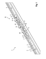
- the guide rail arrangement 1 comprises a guide rail 2, designed as a slide rail.
- the guide rail 2 has a mounting surface 3 with a plurality of mounting holes 5. About this mounting holes 5, the guide rail 2 can be screwed to a frame, a door or wall. Perpendicular to the mounting surface 3 are two spaced side walls. 4
- a moving element 6 is guided in the direction of movement 8 linearly movable in the guide rail 2.
- an eye 7 is formed in the moving element 6.
- the movement element 6 is fixedly connected to a first latching lug 9.
- a detent 10 located in the guide rail 2, a detent 10.
- This detent 10 is guided linearly movable within the guide rail 2.
- the latching detent 10 is fixed in the guide rail 2.
- the latching detent 10 comprises a block 11, which is fixed in the guide rail 2 via a screw 12.
- the block 11 comprises a first web 13 and a second web 14.
- the two webs 13, 14 extend in a direction perpendicular to the mounting surface 3.
- a through hole is provided in each of the two webs 13, 14, a through hole is provided. The through holes extend parallel to the direction of movement 8.
- a coil spring 15 is arranged between the two webs 13, 14 .
- the coil spring 15 is mounted at one end via a spring force adjustment 16 in the first block 13.
- the other end of the spring 15 is stuck on a plunger 17.
- the plunger 17 is mounted linearly movable in the second web 14.
- the latching detent 10 has a rocker arm 18. At this rocker arm 18, a second latching lug 19 is formed.
- the second latching lug 19 is formed as a roller.
- the second latching lug 19 can engage and disengage with the first latching lug 9. In this case, only the second locking lug 19 pivots.
- FIG. 2 shows a detail FIG. 1 , In FIG. 2 the guide rail 2 and the block 11 are hidden. This makes it easy to see that the rocker arm 19 is L-shaped. At one end of the L, the second locking lug 19 is arranged. The other end of the L-shaped rocker arm 18 has an axis of rotation 20. The axis of rotation 20 extends parallel to the mounting surface 3 and perpendicular to the direction of movement 8. The plunger 17 presses against the rocker arm 18 so that upon engagement and disengagement of the two locking lugs 9, 19 of the rocker arm 18 and thus also the second latching lug 19 against the spring force the spring 15 is moved.
- FIG. 2 an axis 21 of the eye 7. This axis 21 is perpendicular to the direction of movement 8 and perpendicular to the mounting surface. 3
- FIG. 3 shows a second embodiment of the guide rail assembly 1.
- the guide rail 2 is hidden here.
- Identical or functionally identical components are provided with the same reference numerals in all embodiments.
- the block 11 is fixed directly on the screw 12 in the guide rail 2.
- a plate carriage 22 is provided. This plate carriage 22 is fixed via the screw 12 in the guide rail 2.
- two upwardly bent screw fastening tongues 24 are provided on the plate carriage 22.
- the block 11 is seated between these two screw connection lugs 24.
- the block 11 is firmly connected to the plate carriage 22 via a slide screw connection 24 which passes through the two screw connection lugs 24.
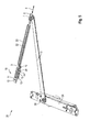
- FIGS. 4 and 5 show a Matbetuschigeran Aunt 26.
- the door actuator assembly 26 includes a door operator 29, designed as a door closer, a lever 31 and a guide rail assembly 1, as just described.
- FIG. 4 shows the door operator 29 is embedded or integrated into the frame of a door leaf 28.
- the guide rail assembly 1 is inserted or integrated into the frame of a door frame 27.
- FIG. 5 the door frame 27 and the door leaf 28 are hidden.
- the door operator 29 includes an output shaft 30.
- This output shaft 30 is rotatably connected to the lever 31.
- the other end of the lever 31 is rotatably connected via the eye 7 with the moving member 6. In the closed state of the door leaf 28, the entire Matrix Aunt 26 is not visible.
- FIG. 5 shows that the guide rail assembly 1 comprises an extension 32.
- This extension 32 is connected at one end to the moving element 6 and at the other end to the first latching lug 9.
- a sliding attachment 33 is pushed onto the extension 32, so that the extension 32 is supported via the sliding attachment 33 in the guide rail 2.
- the moving element 6 moves to the right and the lever 31 is arranged parallel to the guide rail 2 at.
- the extension 32 is provided so that the latching detent 10 can be offset as far as possible to the left.
- the length of the extension 32 must in particular be chosen so that in the closed state, the output shaft 33 between the latching detent 10 and the moving element 6 finds room.
Landscapes
- Engineering & Computer Science (AREA)
- Mechanical Engineering (AREA)
- Support Devices For Sliding Doors (AREA)
Applications Claiming Priority (1)
| Application Number | Priority Date | Filing Date | Title |
|---|---|---|---|
| DE102012104852A DE102012104852A1 (de) | 2012-06-05 | 2012-06-05 | Führungsschienenanordnung |
Publications (2)
| Publication Number | Publication Date |
|---|---|
| EP2672046A2 true EP2672046A2 (fr) | 2013-12-11 |
| EP2672046A3 EP2672046A3 (fr) | 2017-05-10 |
Family
ID=48190062
Family Applications (1)
| Application Number | Title | Priority Date | Filing Date |
|---|---|---|---|
| EP13002216.3A Withdrawn EP2672046A3 (fr) | 2012-06-05 | 2013-04-26 | Agencement de rail de guidage |
Country Status (2)
| Country | Link |
|---|---|
| EP (1) | EP2672046A3 (fr) |
| DE (1) | DE102012104852A1 (fr) |
Cited By (2)
| Publication number | Priority date | Publication date | Assignee | Title |
|---|---|---|---|---|
| EP2899350A1 (fr) * | 2014-01-23 | 2015-07-29 | Koblenz S.P.A. | Dispositif d'arrêt et d'amortissement pour unités de chariot de portes coulissantes de bâtiments ou d'ameublement et analogues |
| EP3489445A1 (fr) | 2017-11-22 | 2019-05-29 | dormakaba Deutschland GmbH | Dispositif de verrouillage, en particulier dispositif de maintien en position ouverte pour un ensemble d'actionnement de porte |
Families Citing this family (1)
| Publication number | Priority date | Publication date | Assignee | Title |
|---|---|---|---|---|
| EP3739156A1 (fr) * | 2019-05-14 | 2020-11-18 | dormakaba Deutschland GmbH | Dispositif de maintien en position ouverte et ensemble porte |
Family Cites Families (3)
| Publication number | Priority date | Publication date | Assignee | Title |
|---|---|---|---|---|
| DE102005014061B3 (de) * | 2005-03-23 | 2006-11-16 | Dorma Gmbh + Co. Kg | Feststellvorrichtung für Türflügel mit einem Türschließer |
| DE102008048994B4 (de) * | 2008-09-25 | 2010-05-27 | Geze Gmbh | Feststellvorrichtung für einen Flügel einer Tür |
| DE102008048992B4 (de) * | 2008-09-25 | 2013-05-16 | Geze Gmbh | Feststellvorrichtung für einen Flügel einer Tür |
-
2012
- 2012-06-05 DE DE102012104852A patent/DE102012104852A1/de not_active Withdrawn
-
2013
- 2013-04-26 EP EP13002216.3A patent/EP2672046A3/fr not_active Withdrawn
Non-Patent Citations (1)
| Title |
|---|
| None |
Cited By (3)
| Publication number | Priority date | Publication date | Assignee | Title |
|---|---|---|---|---|
| EP2899350A1 (fr) * | 2014-01-23 | 2015-07-29 | Koblenz S.P.A. | Dispositif d'arrêt et d'amortissement pour unités de chariot de portes coulissantes de bâtiments ou d'ameublement et analogues |
| RU2667137C2 (ru) * | 2014-01-23 | 2018-09-14 | Кобленц С.п.А. | Стопорное и демпфирующее устройство для узлов каретки раздвижных дверей для зданий или мебели и подобных им |
| EP3489445A1 (fr) | 2017-11-22 | 2019-05-29 | dormakaba Deutschland GmbH | Dispositif de verrouillage, en particulier dispositif de maintien en position ouverte pour un ensemble d'actionnement de porte |
Also Published As
| Publication number | Publication date |
|---|---|
| DE102012104852A1 (de) | 2013-12-05 |
| EP2672046A3 (fr) | 2017-05-10 |
Similar Documents
| Publication | Publication Date | Title |
|---|---|---|
| EP3973126B1 (fr) | Ferrure de meuble | |
| EP2594713B1 (fr) | Ouverture de porte | |
| EP2828460A1 (fr) | Ferrure pour un ouvrant de fenêtre ou de porte qui peut être déplacé par un mouvement parallèle et être déplacé en translation horizontalement dans cette position écartée en parallèle | |
| DE102012104851A1 (de) | Führungsschienenanordnung | |
| EP2672046A2 (fr) | Agencement de rail de guidage | |
| EP1568833B1 (fr) | Gâche pour une fenêtre ou une porte | |
| AT414115B (de) | Bodenverriegelung | |
| EP2840214A1 (fr) | Dispositif ferme-porte | |
| EP3763911B1 (fr) | Dispositif de rail de guidage pour un portail roulant ou un grillage roulant | |
| EP2672041A2 (fr) | Agencement de rail de guidage | |
| EP2885475B1 (fr) | Barre de pression avec dispositif de tension | |
| DE102014216722A1 (de) | Steuerelement für eine Beschlaganordnung | |
| DE102013212650B3 (de) | Vorrichtung zur Regelung der Schließfolge einer zweiflügeligen Drehtüranlage | |
| EP2818618B1 (fr) | Dispositif de régulation de la séquence de fermeture d'une installation de porte rotative à deux battants | |
| EP2636833A1 (fr) | Ensemble de rail de guidage | |
| EP2072730A2 (fr) | Agencement d'armature pour éléments relevables-coulissants et éléments relevables-coulissants | |
| EP2672048B1 (fr) | Agencement d'actionnement de porte | |
| EP2674558B1 (fr) | Agencement d'actionnement de porte | |
| DE102013226720B4 (de) | Einstellbare Vertikalaussteifung mit Gleiter für einen abstellbaren Flügel eines Fensters einer Tür oder dergleichen | |
| EP3985219A1 (fr) | Agencement doté d'un joint d'étanchéité de plancher pour une porte, un espace intermédiaire se trouvant entre un battant de porte et un cadre, dans lequel passe le seul axe de rotation du battant | |
| EP4390041A1 (fr) | Ensemble de transmission pour actionner un joint de porte automatique et joint de porte comprenant ledit ensemble de transmission | |
| EP2090730B1 (fr) | Dispositif de verrouillage | |
| DE102014100439A9 (de) | Schließfolgeregelung | |
| EP2754816A2 (fr) | Dispositif d'arrêt | |
| EP2674557A2 (fr) | Agencement d'actionnement de porte |
Legal Events
| Date | Code | Title | Description |
|---|---|---|---|
| PUAI | Public reference made under article 153(3) epc to a published international application that has entered the european phase |
Free format text: ORIGINAL CODE: 0009012 |
|
| AK | Designated contracting states |
Kind code of ref document: A2 Designated state(s): AL AT BE BG CH CY CZ DE DK EE ES FI FR GB GR HR HU IE IS IT LI LT LU LV MC MK MT NL NO PL PT RO RS SE SI SK SM TR |
|
| AX | Request for extension of the european patent |
Extension state: BA ME |
|
| RAP1 | Party data changed (applicant data changed or rights of an application transferred) |
Owner name: DORMA DEUTSCHLAND GMBH |
|
| PUAL | Search report despatched |
Free format text: ORIGINAL CODE: 0009013 |
|
| RAP1 | Party data changed (applicant data changed or rights of an application transferred) |
Owner name: DORMAKABA DEUTSCHLAND GMBH |
|
| AK | Designated contracting states |
Kind code of ref document: A3 Designated state(s): AL AT BE BG CH CY CZ DE DK EE ES FI FR GB GR HR HU IE IS IT LI LT LU LV MC MK MT NL NO PL PT RO RS SE SI SK SM TR |
|
| AX | Request for extension of the european patent |
Extension state: BA ME |
|
| RIC1 | Information provided on ipc code assigned before grant |
Ipc: E05F 3/22 20060101AFI20170405BHEP |
|
| STAA | Information on the status of an ep patent application or granted ep patent |
Free format text: STATUS: THE APPLICATION HAS BEEN PUBLISHED |
|
| STAA | Information on the status of an ep patent application or granted ep patent |
Free format text: STATUS: REQUEST FOR EXAMINATION WAS MADE |
|
| STAA | Information on the status of an ep patent application or granted ep patent |
Free format text: STATUS: THE APPLICATION IS DEEMED TO BE WITHDRAWN |
|
| 17P | Request for examination filed |
Effective date: 20171116 |
|
| RBV | Designated contracting states (corrected) |
Designated state(s): AL AT BE BG CH CY CZ DE DK EE ES FI FR GB GR HR HU IE IS IT LI LT LU LV MC MK MT NL NO PL PT RO RS SE SI SK SM TR |
|
| 18D | Application deemed to be withdrawn |
Effective date: 20171111 |