EP1473436B1 - Coiffe d'obturateur de puits à libération rapide - Google Patents
Coiffe d'obturateur de puits à libération rapide Download PDFInfo
- Publication number
- EP1473436B1 EP1473436B1 EP04101771A EP04101771A EP1473436B1 EP 1473436 B1 EP1473436 B1 EP 1473436B1 EP 04101771 A EP04101771 A EP 04101771A EP 04101771 A EP04101771 A EP 04101771A EP 1473436 B1 EP1473436 B1 EP 1473436B1
- Authority
- EP
- European Patent Office
- Prior art keywords
- bonnet
- bop
- latching
- radial lock
- radial
- Prior art date
- Legal status (The legal status is an assumption and is not a legal conclusion. Google has not performed a legal analysis and makes no representation as to the accuracy of the status listed.)
- Expired - Lifetime
Links
- 230000007246 mechanism Effects 0.000 claims description 87
- 210000003660 reticulum Anatomy 0.000 description 246
- 241000282472 Canis lupus familiaris Species 0.000 description 86
- 238000006073 displacement reaction Methods 0.000 description 27
- 239000000463 material Substances 0.000 description 25
- 238000005553 drilling Methods 0.000 description 15
- 239000012530 fluid Substances 0.000 description 15
- 230000000712 assembly Effects 0.000 description 12
- 238000000429 assembly Methods 0.000 description 12
- 230000004913 activation Effects 0.000 description 11
- 230000008878 coupling Effects 0.000 description 11
- 238000010168 coupling process Methods 0.000 description 11
- 238000005859 coupling reaction Methods 0.000 description 11
- 239000007789 gas Substances 0.000 description 10
- 238000007789 sealing Methods 0.000 description 8
- 238000012856 packing Methods 0.000 description 7
- 230000015572 biosynthetic process Effects 0.000 description 6
- 229920001971 elastomer Polymers 0.000 description 6
- 239000000806 elastomer Substances 0.000 description 6
- 238000012423 maintenance Methods 0.000 description 6
- 238000000034 method Methods 0.000 description 6
- 238000009844 basic oxygen steelmaking Methods 0.000 description 5
- 229910052751 metal Inorganic materials 0.000 description 5
- 239000002184 metal Substances 0.000 description 5
- 238000013461 design Methods 0.000 description 4
- 238000004519 manufacturing process Methods 0.000 description 4
- 229910000831 Steel Inorganic materials 0.000 description 3
- 238000005452 bending Methods 0.000 description 3
- 230000006378 damage Effects 0.000 description 3
- 230000009977 dual effect Effects 0.000 description 3
- 230000000694 effects Effects 0.000 description 3
- 239000007787 solid Substances 0.000 description 3
- 239000010959 steel Substances 0.000 description 3
- PXHVJJICTQNCMI-UHFFFAOYSA-N Nickel Chemical compound [Ni] PXHVJJICTQNCMI-UHFFFAOYSA-N 0.000 description 2
- RTAQQCXQSZGOHL-UHFFFAOYSA-N Titanium Chemical compound [Ti] RTAQQCXQSZGOHL-UHFFFAOYSA-N 0.000 description 2
- 208000027418 Wounds and injury Diseases 0.000 description 2
- 229910045601 alloy Inorganic materials 0.000 description 2
- 239000000956 alloy Substances 0.000 description 2
- WYTGDNHDOZPMIW-RCBQFDQVSA-N alstonine Natural products C1=CC2=C3C=CC=CC3=NC2=C2N1C[C@H]1[C@H](C)OC=C(C(=O)OC)[C@H]1C2 WYTGDNHDOZPMIW-RCBQFDQVSA-N 0.000 description 2
- 230000008901 benefit Effects 0.000 description 2
- DMFGNRRURHSENX-UHFFFAOYSA-N beryllium copper Chemical compound [Be].[Cu] DMFGNRRURHSENX-UHFFFAOYSA-N 0.000 description 2
- 238000000576 coating method Methods 0.000 description 2
- 238000005552 hardfacing Methods 0.000 description 2
- 208000014674 injury Diseases 0.000 description 2
- 238000007689 inspection Methods 0.000 description 2
- 238000009434 installation Methods 0.000 description 2
- 239000007788 liquid Substances 0.000 description 2
- 230000014759 maintenance of location Effects 0.000 description 2
- 230000013011 mating Effects 0.000 description 2
- 239000000203 mixture Substances 0.000 description 2
- 238000000926 separation method Methods 0.000 description 2
- 239000010936 titanium Substances 0.000 description 2
- 229910052719 titanium Inorganic materials 0.000 description 2
- 230000007704 transition Effects 0.000 description 2
- 229910052582 BN Inorganic materials 0.000 description 1
- PZNSFCLAULLKQX-UHFFFAOYSA-N Boron nitride Chemical compound N#B PZNSFCLAULLKQX-UHFFFAOYSA-N 0.000 description 1
- 229920000049 Carbon (fiber) Polymers 0.000 description 1
- 235000019738 Limestone Nutrition 0.000 description 1
- 239000004696 Poly ether ether ketone Substances 0.000 description 1
- 229910001069 Ti alloy Inorganic materials 0.000 description 1
- 239000000853 adhesive Substances 0.000 description 1
- 230000001070 adhesive effect Effects 0.000 description 1
- JUPQTSLXMOCDHR-UHFFFAOYSA-N benzene-1,4-diol;bis(4-fluorophenyl)methanone Chemical compound OC1=CC=C(O)C=C1.C1=CC(F)=CC=C1C(=O)C1=CC=C(F)C=C1 JUPQTSLXMOCDHR-UHFFFAOYSA-N 0.000 description 1
- 239000004917 carbon fiber Substances 0.000 description 1
- 230000008859 change Effects 0.000 description 1
- 238000006243 chemical reaction Methods 0.000 description 1
- 239000002131 composite material Substances 0.000 description 1
- 230000009849 deactivation Effects 0.000 description 1
- 230000005489 elastic deformation Effects 0.000 description 1
- 239000011152 fibreglass Substances 0.000 description 1
- 238000007667 floating Methods 0.000 description 1
- 239000002783 friction material Substances 0.000 description 1
- 230000004941 influx Effects 0.000 description 1
- 239000006028 limestone Substances 0.000 description 1
- 230000004048 modification Effects 0.000 description 1
- 238000012986 modification Methods 0.000 description 1
- 229910052759 nickel Inorganic materials 0.000 description 1
- 230000000149 penetrating effect Effects 0.000 description 1
- 229920002530 polyetherether ketone Polymers 0.000 description 1
- -1 polytetrafluoroethylene Polymers 0.000 description 1
- 229920001343 polytetrafluoroethylene Polymers 0.000 description 1
- 239000004810 polytetrafluoroethylene Substances 0.000 description 1
- 230000008569 process Effects 0.000 description 1
- 230000004044 response Effects 0.000 description 1
- 230000000717 retained effect Effects 0.000 description 1
- 238000007665 sagging Methods 0.000 description 1
- 230000035945 sensitivity Effects 0.000 description 1
- UONOETXJSWQNOL-UHFFFAOYSA-N tungsten carbide Chemical compound [W+]#[C-] UONOETXJSWQNOL-UHFFFAOYSA-N 0.000 description 1
- XLYOFNOQVPJJNP-UHFFFAOYSA-N water Substances O XLYOFNOQVPJJNP-UHFFFAOYSA-N 0.000 description 1
Images






Classifications
-
- E—FIXED CONSTRUCTIONS
- E21—EARTH OR ROCK DRILLING; MINING
- E21B—EARTH OR ROCK DRILLING; OBTAINING OIL, GAS, WATER, SOLUBLE OR MELTABLE MATERIALS OR A SLURRY OF MINERALS FROM WELLS
- E21B33/00—Sealing or packing boreholes or wells
- E21B33/02—Surface sealing or packing
- E21B33/03—Well heads; Setting-up thereof
- E21B33/06—Blow-out preventers, i.e. apparatus closing around a drill pipe, e.g. annular blow-out preventers
- E21B33/061—Ram-type blow-out preventers, e.g. with pivoting rams
- E21B33/062—Ram-type blow-out preventers, e.g. with pivoting rams with sliding rams
- E21B33/063—Ram-type blow-out preventers, e.g. with pivoting rams with sliding rams for shearing drill pipes
-
- E—FIXED CONSTRUCTIONS
- E21—EARTH OR ROCK DRILLING; MINING
- E21B—EARTH OR ROCK DRILLING; OBTAINING OIL, GAS, WATER, SOLUBLE OR MELTABLE MATERIALS OR A SLURRY OF MINERALS FROM WELLS
- E21B33/00—Sealing or packing boreholes or wells
- E21B33/02—Surface sealing or packing
- E21B33/03—Well heads; Setting-up thereof
- E21B33/06—Blow-out preventers, i.e. apparatus closing around a drill pipe, e.g. annular blow-out preventers
- E21B33/061—Ram-type blow-out preventers, e.g. with pivoting rams
- E21B33/062—Ram-type blow-out preventers, e.g. with pivoting rams with sliding rams
Definitions
- BOP blowout preventer
- a wellbore may penetrate a layer having a formation pressure substantially higher than the pressure maintained in the wellbore.
- the pressure increase associated with the kick is generally produced by an influx of formation fluids (which may be a liquid, a gas, or a combination thereof) into the wellbore.
- the relatively high pressure kick tends to propagate from a point of entry in the wellbore uphole (from a high pressure region to a low pressure region). If the kick is allowed to reach the surface, drilling fluid, well tools, and other drilling structures may be blown out of the wellbore.
- These "blowouts” often result in catastrophic destruction of the drilling equipment (including, for example, the drilling rig) and in substantial injury or death of rig personnel.
- each bonnet Interior of each bonnet is a piston actuated ram.
- the rams may be either pipe rams (which, when activated, move to engage and surround drillpipe and well tools to seal the wellbore) or shear rams (which, when activated, move to engage and physically shear any drillpipe or well tools in the wellbore).
- the rams typically are located opposite of each other and, whether pipe rams or shear rams, the rams typically seal against each other proximate a center of the wellbore in order to completely seal the wellbore.
- bonnets are typically connected to the BOP body by bolts or a combination of a hinge and bolts.
- the bolts must be highly torqued in order to maintain a seal between a bonnet door and the BOP body.
- the seal between the bonnet and the BOP body is generally a face seal, and the seal must be able to withstand the very high pressures present in the wellbore.
- U.S. Patent No. 5,897,094 issued to Brugman et al. discloses an improved BOP door connection that includes upper and lower connector bars for securing bonnets to the BOP.
- the improved BOP door connection of the '094 patent does not use bolts to secure the bonnets to the BOP and discloses a design that seeks to minimize a stack height of the BOP.
- U.S. Patent No. 6,554,247 discloses bonnet lock mechanism for a BOP includes a radial lock, a radial lock displacement device, and at least one lock actuator operatively coupled to the radial lock displacement device.
- the radial lock displacement device is adapted to radially displace the radial lock to form a locking engagement between a bonnet and a body of the blowout preventer.
- a radial locking mechanism is cooperatively attached to each bonnet and is adapted to secure each bonnet to the body proximate an inner perimeter of the at least two side openings.
- a ram (not shown) is generally coupled to the ram piston 22, and, if the rams (not shown) are shear rams, the axial displacement of the ram piston 22 generally moves the ram (not shown) into the internal bore 18 and into contact with a corresponding ram (not shown) coupled to a ram piston 22 in a bonnet assembly 14 disposed on an opposite side of the BOP 10.
- the ram (not shown) is a pipe ram
- activation of the ram piston 22 moves the ram (not shown) into position to seal around drillpipe (not shown) or well tools (not shown) passing through the internal bore 18 in the BOP body 12.
- the ram (not shown) is a shear ram
- activation of the ram piston 22 moves the ram (not shown) into position to shear any drillpipe (not shown) or well tools (not shown) passing through the internal bore 18 of the BOP body 12 and, therefore, seal the internal bore 18.
- FIG. 1 shows a radial lock mechanism 28 that is designed to provide a high pressure locking mechanism that retains a high pressure radial seal between the bonnet assembly 14 and the BOP body 12. Moreover, the radial lock mechanism 28 is designed to simplify maintenance of the bonnet assembly 14 and the rams (not shown) positioned therein.
- the bonnet body 30 When the bonnet seal 29 is formed between the bonnet body 30 and the BOP body 12, the bonnet body 30 is in an installed position and is located proximate the BOP body 12 and at least partially within the side passage 20. Because the bonnet seal 29 is a high pressure seal, the radial lock mechanism 28 must be robust and able to withstand very high pressures present in the internal bore 18.
- the bonnet assembly shown in Figure 1 comprises a novel mechanism for locking the bonnet assembly 14 (and, as a result, the bonnet seal 29 ) in place.
- the radial lock 32 has an inner diameter adapted to fit over an exterior surface 40 of the bonnet body 30 and slide into a position adjacent a sealing end of the bonnet body 30 .
- the radial lock 32 shown in Figure 2 comprises two halves separated by a center cut 46 .
- the radial lock 32 may comprise additional segments and the two segment radial lock shown in Figure 2 is not intended to limit the scope of the invention. Additional examples of the radial lock 32 will be described in greater detail below.
- the bonnet assembly 14 is adapted to slidably engage at least one rod 70 through a swivel slide mount 74 (note that two rods 70 are shown slidably engaged, through the swivel slide mounts 74 , with each bonnet assembly 14 in Figure 1).
- the bonnet assembly 14 may slide along the rods 70 .
- the slidable engagement permits the bonnet assembly 14 to be moved into and out of locking and sealing engagement with the BOP body 12.
- the lock actuators 38 are coupled to the bonnet door 36 with either a fixed or removable coupling comprising bolts, adhesive, welds, threaded connections, or similar means known in the art.
- the lock actuators 38 are also cooperatively coupled to the radial lock displacement device 34 in a similar fashion. Additionally, the coupling between the lock actuators 38 and the radial lock displacement device 34 may be a simple contact engagement.
- Figure 1 shows two lock actuators 38 coupled to each bonnet door 36 . However, a single lock actuator cylinder 38 or a plurality of lock actuators 38 may be used.
- the lock actuators 38 shown are generally hydraulic cylinders; however, other types of lock actuators (including, for example, pneumatic actuators, electrically powered motors, and the like) are known in the art and may be used.
- FIG. 2 A fully assembled view of the bonnet assembly 14 including the radial lock mechanism 28 is shown in Figure 2.
- the bonnet assembly 14 is first moved into position proximate the BOP body 12 by sliding the bonnet assembly 14 toward the BOP body 12 on the rods 70.
- the lock actuators 38 are then activated so that they axially displace (wherein an axis of displacement corresponds to an axis of the side passage 20 ) the radial lock displacement device 34 in a direction toward the BOP body 12 .
- the radial lock 32 and the high pressure bonnet seal 29 can withstand the high forces generated by the high pressures present within the internal bore 18 of the BOP body 12 because of the locking engagement between the radial lock 32 and the inner radial lock surface 58 of the BOP body 12 .
- the radial lock mechanism 28 may be disengaged by reversing the activation of the lock actuators 38 (e.g ., after the pressure in the internal bore 18 has been relieved).
- the bonnet assembly comprises a radial lock mechanism 28 that includes a positive disengagement system (e.g. , the lock actuators 38 must be activated in order to disengage the radial lock mechanism 28 ).
- the wedge surface 48 used to radially displace the radial lock 32 may comprise any one of the following examples.
- the wedge surface 48 of the radial lock displacement device 34 may comprise a single actuation step 80 .
- the wedge surface 48 may comprise a dual actuation step 82.
- the single actuation step ( 80 in Figure 3) generally has a shorter actuation stroke than the dual actuation step ( 82 in Figure 4).
- an actuation step angle ( 84 in Figures 3 and 4) is designed to maximize a radial actuation force and minimize a linear actuation force.
- the actuation step angle (84 in Figures 3 and 4) is approximately 45 degrees. In another example, the actuation step angle (84 in Figures 3 and 4) is less than 45 degrees.
- the radial lock displacement device 34 further comprises a slot 90 and at least one retention pin 92 designed to retain the radial lock 32 against the load shoulder 44 of the bonnet body 30 .
- the radial lock 32 is retained in place by the at least one retention pin 92, and the bonnet body 30 and the radial lock 32 are held in a fixed relationship after the radial lock 32 has been actuated and is in locking engagement with the inner radial lock surface (58 in Figure 2) of the side passage (20 in Figure 1).
- the radial locks 100, 106 could be manufactured by, for example, manufacturing a solid radial lock and sequentially saw cutting the solid radial lock into two or more segments. However, other manufacturing techniques are known in the art and may be used to manufacture the radial lock.
- the flexible band 118 may comprise a material with a relatively low elastic modulus (when compared to, for example, the elastic modulus of the individual segments) so that the flexible band 118 can radially expand in response to the radial displacement produced by the radial lock displacement device (34 in Figure 1). Radial expansion of the flexible band 118 results in a locking engagement between the radial lock 112 and the inner radial lock surface ( 58 in Figure 2) of the BOP body ( 12 in Figure 1).
- a radial lock 120 may comprise a single profile engagement including a single radial lock engagement surface 122.
- the single radial lock engagement surface 122 is designed to lockingly engage a BOP engagement surface ( 59 in Figure 2) formed on the inner radial lock surface ( 58 in Figure 2) of the side passage (20 in Figure 1).
- a radial lock 124 comprises a dual profile engagement including two radial lock engagement surfaces 126 .
- the radial lock 124 may also comprise a plurality of radial lock engagement surfaces designed to lockingly engage a corresponding number of BOP engagement surfaces ( 59 in Figure 2) formed on the inner radial lock surface ( 58 in Figure 2) of the side passage (20 in Figure 1) of the BOP body (12 in Figure 1).
- the radial locks described in the referenced examples are designed so that the cross-sectional area of engagement between the radial lock engagement surfaces with the BOP engagement surfaces ( 59 in Figure 2) is maximized. Maximizing the cross-sectional areas of engagement ensures that the radial locks positively lock the bonnet assembly ( 14 in Figure 1) and, as a result, the bonnet seal ( 29 in Figure 1) in place against the high pressures present in the internal bore ( 18 in Figure 1) of the BOP ( 10 in Figure 1). Moreover, as discussed previously, angles of the engagement surfaces may be designed to produce an axial force that firmly pulls the bonnet door ( 36 in Figure 1) against the BOP body (12 in Figure 1) and that in some instances may assist in the activation of the bonnet seal (29 in Figure 1).
- the radial locks and the engagement surfaces described in the foregoing examples may be coated with, for example, hardfacing materials and/or friction reducing materials.
- the coatings may help prevent, for example, galling, and may prevent the radial locks from sticking or "hanging-up" in the engagement surfaces during the activation and/or deactivation of the radial lock mechanism ( 28 in Figure 1).
- the coatings may also increase the life of the radial locks and the engagement surfaces by reducing friction and wear.
- the radial locks described above are designed to operate below an elastic limit of the materials from which they are formed. Operation below the elastic limit ensures that the radial locks will not permanently deform and, as a result of the permanent deformation, lose effectiveness. Accordingly, material selection and cross-sectional area of engagement of the engagement surfaces is very important to the design of the radial lock mechanism (28 in Figure 1).
- the bonnet seal 29 is designed to withstand the high pressures present in the internal bore 18 of the BOP body 12 and to thereby prevent fluids and/or gases from passing from the internal bore 18 to the exterior of the BOP 10.
- the bonnet seal 29 may comprise several different configurations as shown in the following discussion of Figures 13-17.
- the seals disclosed in the discussion below may be formed from a variety of materials.
- the seals may be elastomer seals or non-elastomer seals (such as, for example, metal seals, PEEK seals, etc.).
- Metal seals may further comprise metal-to-metal C-ring seals and/or metal-to-metal lip seals.
- the sealing arrangements shown below may include a combination of seal types and materials. Accordingly, the type of seal, number of seals, and the material used to form radial and face seals are not intended to limit the bonnet seal 29 .
- Figure 13 comprises a bonnet seal 130 formed on a radial perimeter 132 of a bonnet body 133 .
- the radial seal 130 further comprises two o-rings 134 disposed in grooves 136 formed on the radial perimeter 132 of the bonnet body 133 .
- the o-rings 134 sealingly engage an inner sealing perimeter 138 of the side passage ( 20 in Figure 1) in the BOP body 12 .
- the radial seal shown in Figure 13 comprises two grooves 136 , but a single groove or a plurality of grooves may be suitable for use with the o-rings 134 .
- Figure 13 shows two o-rings 134 , a single o-ring or more than two o-rings may be used.
- a bonnet seal 140 comprises at least two packing seals 146 (which may be, for example, t-seals, lip seals, or seals sold under the trademark PolyPak, which is a mark of Parker Hannifin, Inc.) disposed in grooves 148 formed on a radial perimeter 142 of a bonnet body 144 .
- the packing seals 146 sealingly engage an inner sealing perimeter 150 of the side passage (20 in Figure 1) of the BOP body 12.
- the bonnet seal 140 shown in Figure 14 comprises two grooves 148 , but a single groove or a plurality of grooves may be suitable for use with the packing seals 146 .
- Figure 14 shows two packing seals 146, a single seal or more than two seals may be used.
- the bonnet seal 172 comprises a radial seal 174 disposed in a groove 178 formed on a seal carrier 180.
- the seal carrier 180 is disposed in a groove 182 formed in a bonnet body 184 and also comprises a face seal 176 disposed in a groove 177 formed on the seal carrier 180.
- the face seal 176 is adapted to sealingly engage mating face surface 186 of the BOP body 12
- the radial seal is adapted to sealingly engage an inner sealing perimeter 188 formed on the bonnet body 184.
- the bonnet seal 172 may also comprise an energizing mechanism 190 that is adapted to displace the seal carrier 180 in a direction toward the exterior surface 186 of the BOP body 12 so as to energize the face seal 176.
- the energizing mechanism 190 may comprise, for example, a spring, a thrust washer, or a similar structure.
- the energizing mechanism 190 helps ensure that the face seal 176 maintains positive contact with and, thus, maintains a high pressure seal with the exterior surface 186 of the BOP body 12 .
- the energizing mechanism 190 is not required in all embodiments.
- the seal carrier 180 may be designed so that both the radial seal 174 and the face seal 176 are pressure activated without the assistance of an energizing mechanism 190.
- a diameter and an axial thickness of a seal carrier are selected so that high pressure from the internal bore first moves the seal carrier toward the exterior surface of the BOP body. Once the face seal sealingly engages the exterior surface, the high pressure from the internal bore causes the seal carrier to radially expand until the radial seal sealingly engages the groove in the seal carrier.
- the face seal 176 and the radial seal 174 may be, for example, o-rings, packing seals, or any other high pressure seal known in the art.
- Figure 16 only shows single seals disposed in single grooves. However, more than one seal, more than one groove, or a combination thereof may be used.
- the seal carrier 192 as shown in the previous figures is used in combination with a backup seal 194 disposed in a groove 196 on an external surface 198 of a bonnet body 200.
- the backup seal 194 may be an o-ring, a packing seal, a metal seal, or any other high pressure seal known in the art.
- the backup seal 194 further maintains a high pressure seal if, for example, there is leakage from the seals disposed on the seal carrier 192 . Note that Figure 17 does not include an energizing mechanism.
- some of the bonnet seals reduce an axial force necessary to form the bonnet seal.
- the bonnet seals shown above greatly reduce the sensitivity of the bonnet seal to door flex by maintaining a constant squeeze regardless of wellbore pressure.
- the radial seal arrangements also reduce the total area upon which wellbore pressure acts and thus reduces a separation force that acts to push the bonnet door away from the BOP body.
- the radial lock mechanism 220 comprises a radial lock 222 disposed in a recess 224 formed on an internal surface 226 of a side passage 228 of a BOP body 230.
- the operation of the radial lock mechanism 220 differs from the embodiments described above in that securing a bonnet body 232 and, accordingly, a bonnet door (not shown) and a bonnet assembly (not shown), in place is accomplished by actuating the radial lock mechanism 220 in radially inward direction.
- the structure shown in Figure 18 is similar to the structures described above except for the direction of actuation of the radial lock mechanism 220. Therefore, the discussion of the present structure will include a description of how the alternative radial lock mechanism 220 differs from those shown above. Common elements of the bonnet assembly (such as, for example, the bonnet door 36 , the linear rods 70 , etc.) will not be described again in detail. Moreover, it should be noted that the structure of Figure 18 does not require, for example, actuator cylinders or a radial lock displacement device ( e.g ., the structure of Figure 18 does not require an internal actuation mechanism).
- Actuation of the radial lock 222 is in a radially inward direction. Accordingly, the radial lock 222 must be coupled to an actuation mechanism that differs from, for example, the radial lock displacement device ( 34 in Figure 1) and the lock actuators ( 38 in Figure 1) described in the previous examples.
- the radial lock 222 comprises a structure similar to those shown in Figures 6 and 7. As shown in Figure 19, separate halves 236, 238 of the radial lock 222 may be coupled to radially positioned actuators 240.
- the actuators 240 are activated to displace the halves 236, 238 of the radial lock 222 in a radially inward direction so that the radial lock 222 engages a groove ( 244 in Figure 18) formed on an exterior surface ( 246 in Figure 18) of the bonnet body ( 232 in Figure 18).
- the radial lock mechanism ( 220 in Figure 18) locks the bonnet body ( 232 in Figure 18) and, therefore, the bonnet door (not shown) and the bonnet assembly (not shown) in place and energizes the high pressure seal ( 234 in Figure 18).
- the radial lock 222 may comprise more than two parts. If a radial lock 250 comprises, for example, four parts 252, 254, 256, 258, an equal number of actuators 240 (e.g. , four) may be used to actuate the radial lock 250. Alternatively, fewer actuators 240 (e.g., less than four as shown in Figure 20) may be used if an actuator 240 is, for example, coupled to more than one part parts 252, 254, 256, 258 of the radial lock 250.
- the actuators 240 may be hydraulic actuators or any other type of actuator known in the art.
- a radial lock 270 may be formed from a single segment 272 .
- the radial lock 270 is actuated by circumferential actuators 274 coupled to the radial lock 270 and disposed proximate ends 276, 278 of the segment 272 .
- the circumferential actuators 274 move the ends 276, 278 of the segment 272 towards each other and in a radially inward direction as shown by the arrows in Figure 21.
- the dashed line in Figure 21 represents an inner surface 277 of the radial lock 270 after actuation.
- the radial lock 270 when actuated, engages the bonnet body (232 in Figure 18) in a manner similar to that shown in Figure 18.
- the segment 272 of the radial lock 270 may be produced by forming a plurality of kerfs 284 proximate the end segments 280, 282.
- the kerfs 284 may be designed to ease installation of the radial lock 270 in the recess ( 224 in Figure 18) and to improve flexibility for radial deformation of the radial lock 270.
- the kerfs may be of any shape known in the art. For example, Figure 22 shows rectangular kerfs 284. However, the kerfs 284 may preferably be formed in a manner that reduces stress concentrations or stress risers at the edges of the kerfs 284 .
- the kerfs 284 may comprise filleted corners (not shown) or, for example, substantially trapezoidal shapes (not shown) to minimize the effects of stress risers.
- the kerfs 284 may be "graduated,” as shown in Figure 22, to produce a substantially smooth transition between relatively stiff straight segments 286 and relatively flexible end segments 280, 282. Graduation of the kerfs 284 effects a smooth stiffness transition that helps prevent stress risers at the last kerf ( e.g ., at the last kerf proximate the straight segments 286 ).
- the radial lock 270 may be formed from a single material or from different materials (comprising, for example, steel, titanium, beryllium copper, or combinations and/or alloys thereof).
- the curved end segments 280, 282 may be formed from a material that is relatively compliant when compared to a relatively rigid material forming the straight segments 286 ( e.g ., the curved and segments 280, 282 may be formed from a material with an elastic modulus (E C ) that is substantially lower than an elastic modulus (E S ) of the straight segments 286).
- E C elastic modulus
- E S elastic modulus
- the radial lock 270 of Figure 21 may comprise more than one segment (e.g ., two halves or a plurality of segments) coupled to and actuated by a plurality of circumferential actuators.
- the radial lock 270 may also comprise a plurality of separate dies or dogs coupled by a flexible band. The dies may be separated by gaps, and the distance of separation may be selected to provide a desired flexibility for the radial lock 270.
- the dies and the flexible banding may comprise different materials.
- the dies may be formed from a substantially stiff material (e.g ., a material with a relatively high modulus of elasticity) comprising, for example, steel or nickel based alloys.
- the flexible banding in contrast, may be formed from materials having a relatively lower modulus elasticity and comprising, for example, titanium alloys or pultruded flats or shapes comprising fiberglass, carbon fibers, or composite materials thereof.
- the radial locks of the embodiments shown in Figures 19-22 may be coated with, for example, hardfacing materials (comprising, for example, tungsten carbide, boron nitride, and similar materials known in the art) or low-friction materials (comprising, for example, polytetrafluoroethylene and similar materials known in the art) to, for example, reduce friction and wear and improve the longevity of the parts.
- hardfacing materials comprising, for example, tungsten carbide, boron nitride, and similar materials known in the art
- low-friction materials comprising, for example, polytetrafluoroethylene and similar materials known in the art
- the radial locks shown in Figures 19-22 may be advantageous because of a reduced bonnet assembly weight and accordingly, reduced overall weight of the BOP. Moreover, there is a potential to retrofit old BOPs to include the radial lock mechanism.
- swivel slide mounts 74 cooperatively attached to the rods 70 and to each of the bonnet assemblies 14 .
- the bonnet assemblies 14 are coupled to the swivel slide mounts 74 , and the swivel slide mounts 74 are slidably engaged with the rods 70.
- the swivel slide mounts 74 are adapted to allow the bonnet assemblies 14 to rotate proximate their axial centerlines so that the rams (not shown) and the interior components of both the bonnet assemblies 14 and the BOP body 12 may be accessed for maintenance, to change the rams, etc.
- the swivel slide mount 74 comprises a swivel slide mounting bar 76 and a swivel plate 78.
- the swivel slide mounting bar 76 is slidably attached to the rods 70.
- the slidable attachment between the swivel slide mounting bar 76 and the rods 70 may be made with, for example, linear bearings 87 that are coupled to the swivel slide mounting bar 76 .
- other slidable attachments known in the art may be used to form the slidable attachment.
- bushings (not shown), or a combination of linear bearings 87 and bushings (not shown) may be used.
- the swivel plate 78 is rotationally attached to the swivel slide mounting bar 76 and is cooperatively attached to an upper surface 75 of the bonnet assembly 14.
- the cooperative attachment of the swivel slide mount 74 to the bonnet assembly 14 is made substantially at an axial centerline of the bonnet assembly 14 .
- the rods 70 are designed to be of sufficient length to permit the bonnet assembly 14 to disengage from the BOP body 12 and slide away from the BOP body 12 until the ram (not shown) is completely outside the side passage 20.
- a point of attachment 82 where the swivel slide mount 74 is cooperatively attached to the upper surface 75 of the bonnet assembly 14 may be optimized so that the point of attachment 82 is substantially near a center of mass of the bonnet assembly 14. Positioning the point of attachment 82 substantially near the center of mass reduces the force required to rotate the bonnet assembly 14 and also reduces the bending stress experienced by the swivel plate 78.
- the swivel plate 78 may further include a bearing 85.
- the bearing 85 may be cooperatively attached to the swivel slide mounting bar 76 and adapted to withstand both radial and thrust loads generated by the rotation of the bonnet assembly 14.
- the bearing 85 may comprise, for example, a combination radial bearing and thrust bearing (such as, for example, a tapered roller bearing).
- the bearing 85 may comprise, for example, a roller bearing to support radial loads and a thrust washer to support axial loads.
- other types of bearing arrangements are known in the art and may be used with the swivel plate 78 .
- Figure 25 shows a top view of the BOP 10 when one of the bonnet assemblies 14 has been disengaged from the BOP body 12 and rotated approximately 90 degrees.
- the ram block attachment point 80 is clearly visible and may be vertically accessed.
- Vertical access is a significant advantage because prior art bonnets that include hinges generally pivot about an edge of the bonnet door. Therefore, if, for example, a lower BOP bonnet was unbolted and pivoted open, the ram could not be vertically accessed because the body of the upper BOP bonnet was in the way. Vertical access to the ram is important because it makes it much easier to maintain or replace rams, thus reducing the time required to maintain the BOP and increasing the level of safety of the personnel performing the maintenance. Further, vertical access enables, for example, maintenance of a lower BOP bonnet while an upper bonnet is locked in position (see, for example, Figures 23-25).
- the bonnet assembly 14 may also be rotated approximately 90 degrees in the other direction with respect to an axis of the side passage ( 20 in Figure 1), thereby permitting approximately 180 degrees of rotation.
- other bonnet assembly may be designed that permit rotation of greater than or less than 180 degrees.
- the range of rotation of the swivel slide mount 74 is not intended to be a limitation.
- the swivel slide mount 74 is advantageous because of the simplicity of the design and attachment to the bonnet assembly 14 .
- prior art hinges are generally complex, difficult to manufacture, and relatively expensive.
- prior art hinges have to be robust because they carry the full weight of the BOP bonnet about a vertical axis positioned some distance away from the center of mass of the bonnet. The bending moment exerted on the hinge is, as a result, very high and deformation of the hinge can lead to "sagging" of the bonnet.
- FIGS 26-37B show embodiments of latching mechanisms for latching a bonnet to BOP body.
- the embodiments described are only provided as examples of latching mechanisms that can be used in accordance with the invention.
- the invention is not limited by any one mechanism.
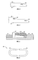
- Figure 26 shows a cutaway of one embodiment of a latch mechanism 610.
- a BOP body 602 and a bonnet 604 are held securely together by latch mechanism 610.
- the mechanism 610 includes a radial lock 612, 614 and a radial lock displacement device 616, 618, similar to those described above.
- the radial lock in this embodiment, comprises only straight sections 612, 614 .
- a first straight section 612 extends horizontally and a second straight section 614 extends vertically. It is understood that in some embodiments two additional straight sections, one horizontal and one vertical, may be positioned on sides of the bonnet 604 that are not shown in the cutaway of Figure 26.
- the radial lock displacement also comprises a horizontal section 616 and a vertical section 618 that radially displace the horizontal and vertical sections 612 , 614 of the radial lock. It is understood that in some embodiments another horizontal and another vertical section (not shown) may be used on the sides of the bonnet 604 not shown in Figure 26.
- the radial lock has no curved (or radial) sections. Only straight sections 612, 614 are displaced into locking engagement with a corresponding radial lock surface (not shown) of the BOP body 602. In at least one embodiment, each of the straight sections comprises a plurality of smaller sections.
- FIG. 27A Another embodiment of a latching mechanism is shown in Figure 27A.
- a bonnet 704 is securely coupled to a BOP body 702 by a latching dog 712 disposed inside the bonnet 704.
- the latching dog 712 includes a tapered edge 714 that lockingly engages with an angled surface 706 of the BOP body 702 to lock the bonnet 704 with the BOP body 702 , even under the high pressure experienced during a blowout.
- the angle of the tapered edge 714 may be selected so that the extension of the latching dog 712 will pull the bonnet 704 axially towards the BOP body 702 an into the proper coupled position, in the event it is not in that position when the latching mechanism is engaged.
- the taper angle may be a "locking taper.”
- a locking taper is a taper having an angle selected such that the latching dog 714 will not be forced toward a retracted position by pressure that tends to force the bonnet 704 and the BOP body 702 away from each other.
- a locking taper has an angle between 3 degrees and 10 degrees. In at least one embodiment, a locking taper is about 6 degrees.
- the latching dog 712 is coupled to a shaft 716 and a piston 718.
- the actuator may be driven by hydraulic fluid, a pneumatic fluid, a motor, or any other actuation means that is know in the art. Those having skill in the art will be able devise other methods for actuating the latching dog 712 .
- a spring 719 is included to provide upward force that will tend to push the latching dog 712 into locking engagement with the angled surface 706 of the BOP body 702.
- the shaft 716 may be sealed with seals 720 so that hydraulic fluids cannot escape the inside of the bonnet 704 during operation of the latching mechanism.
- FIG. 27A and 27B has a latching dog 712 positioned in the bonnet 704 and able to extend into engagement with the BOP body 702.
- the latching dogs may also be disposed in a BOP body such that the latching dogs would extend into locking engagement with an angled surface of the bonnet.
- all of the embodiments described below include a latching mechanism with elements that engage to couple a bonnet and a BOP body. It is expressly within the scope of the invention to have those elements disposed in or on the bonnet to be interchanged with those disposed in or on the BOP body.
- the latching dog 712 may be coupled to the shaft 716 by any means known in the art.
- the shaft 716 may be coupled to the latching dog 712 by a threaded connection. Such a connection would enable the latching dog 712 to be moved in the upward and downward directions.
- Figure 28B shows another embodiment of a floating coupling between a latching dog 742 and a shaft 746.
- the latching dog 742 includes a groove 748
- the shaft 746 includes a tongue 749.
- the engagement of the tongue 749 and the groove 748 creates a "tongue-in-groove" connection between the latching dog 742 and the shaft 746.
- FIG 29 shows an embodiment of a bonnet door 900 that may be used with one or more of the latching mechanisms disclosed herein.
- the bonnet door 900 has a front face 902 that faces towards the centerline (not shown) of the BOP body (not shown) when the bonnet is coupled to the BOP body (not shown).
- a hole 904 in the bonnet door 900 enables the ram actuator (not shown) to pass through the bonnet door 900.
- Figures 30A and 30B show one embodiment of a mechanical device that may be used to move latching dogs 1012, 1014, positioned inside a bonnet 1004, into engagement with a BOP body 1002.
- a movable actuator 1006 moves inside the bonnet 1004 to move the latching dogs 1012, 1014 into the engaged position. It is noted that in different embodiments the movable actuator 1006 may move in different ways. For example, in one embodiment, the movable actuator slides. It is also expressly within the scope of this invention to have an actuator on rollers. Those having ordinary skill in the art will be able to devise other ways to facilitate the movement of an actuator.
- Figure 30A shows the latching dogs 1012, 1014 in an unengaged position.
- the latching dogs 1012, 1014 are located in recessed surfaces 1020, 1021 that enable the latching dogs 1012, 1014 to be positioned within the bonnet 1004 .
- the movable actuator 1006 also includes a plurality of support surfaces 1032, 1034 . Inclined surfaces 1022, 1023 are positioned between the recessed surfaces 1020, 1021 and the support surfaces 1032, 1034. As the movable actuator 1006 moves ( e.g. , to the right in Figure 30A), the latching dogs 1012, 1014, which are held in place in the bonnet 1004, are pushed upward into recesses 1024, 1025 in the BOP body 1002.
- Figure 30B shows the latching dogs 1012, 1014 in an engaged position.
- the latching dogs 1012, 1014 have been pushed partially into the BOP body 1002 by the movable actuator 1006.
- the dogs 1012, 1014 are supported on support surfaces 1032, 1034, and the latching dogs 1012, 1014 extend into recesses 1024, 1025 in the BOP body 1002 to form a locking engagement.
- the bonnet 1004 may be unlatched by moving the movable actuator 1006 back to its initial position, as shown in Figure 30A.
- Figure 31 shows another embodiment of a latching mechanism according to the invention.
- a latching dog 1112 in a bonnet 1104 is connected to a recess track 1132 in a movable actuator 1134 by a pin 1114.
- the latching dog 1112 is moved upward into a locking engagement with a recess 1120 in the BOP body 1102.
- the latching dog 1112 returns to the unlatched position.
- the recess track 1132 and the actuator 1134 may form one piece, or they may be formed of separate components that are coupled together.
- the support dog 1214 is coupled to two linear actuators 1232, 1234 that move the support dog 1214 back and forth.
- a recess 1222 in the bonnet 1204 enables the support dog 1214 to move side to side, but not up and down.
- the latching dog 1212 may move up and down, but not side to side.
- the support dog 1214 is moved ( e.g. , to the right in Figure 32)
- the angled bars 1215, 1216 push the latching dog 1212 upward and into a locking engagement with a recess 1220 in the BOP body 1202 .
- the support dog 1214 is moved by only one actuator. Further, in at least one embodiment, the support dog 1214 in moved by manual actuation.
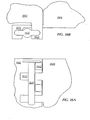
- Figure 33A shows an elevation view of the front face of a bonnet door 1306 of a bonnet 1304 .
- the bonnet door 1306 includes four stick-in dogs 1312 , 1314, 1316 , 1318. While four stick in dogs are shown 1312, 1314, 1316 , 1318, the invention is not limited to four. Any number of stick-in dogs may be used without departing from the scope of the invention.
- FIG 33B shows a close-up of a stick-in dog 1312.
- the stick-in dog 1312 includes three latching members 1332, 1334, 1336 attached circumferentially around a shaft 1330.
- latching member 1332 is attached to the shaft (shown in dashed lines at 1330) at a distance from the bonnet door 1306.
- the tapered surfaces 1414 in the bonnet 1404 are opposed to the tapered surfaces 1412 in the BOP body 1402 in such a way that when the protrusions 1416, 1417 in the BOP body 1402 moves relative to the bonnet 1404 ( e.g. , to the left in Figures 34A and 34B), they lockingly engage the bonnet protrusions 1406, 1407, as shown in Figure 34B.
- the tapered surfaces 1412, 1414 are pressed against each other, the BOP body 1402 and the bonnet 1404 are pulled together. It is noted that either of the bonnet 1404 and the BOP body 1402 could provide moving surfaces, allowing the other components to remain stationary.
- FIGS 35A and 35B show another embodiment of a latching mechanism in accordance with the invention.
- a latching member 1512 is coupled to the BOP body 1502 by a support member 1536.
- the latching member 1512 is also coupled to a linear actuator 1532 by a rod 1534.
- the latching member 1512 includes a tapered surface 1514 opposed to a tapered surface 1524 of the bonnet 1504, when the bonnet is positioned in a side opening of the BOP body (not shown).
- the latching member 1512 is moved closer to the BOP body 1502 so that the tapered surface 1514 on the latching member 1512 contacts the tapered surface 1524 on the bonnet 1504 , as shown in Figure 35B.
- the latching member 1512 is moved by the actuator 1532 , and it slides along the support member 1536 .
- the contact pressure between the tapered surfaces 1514, 1524 pulls the bonnet 1504 closer to the BOP body 1502 .
- the invention in not limited to a linear actuator.
- the latching member 1512 is moved by manual actuation. Those having ordinary skill in the art will be able to devise other activation methods that do not depart from the scope of the invention.
- Figures 36A-36C show another embodiment of a latching mechanism at accordance with the invention.
- Figure 36A shows a side view of a bonnet 1604 and a BOP body 1602 that are coupled together.
- the bonnet 1604 includes a plurality of latching extensions (e.g., latching extension 1612 in Figure 36A) that extend along the side of the BOP body 1602.
- Figure 36B shows a top view of the latching bar 1632 positioned between the bonnet latching dog 1612 and the BOP latching dog 1622. Any forces that would tend to separate the bonnet 1604 and the BOP body 1602 would be absorbed in sheer by the latching bar 1632.
- FIG 36C shows a top view of an embodiment of a latching mechanism.
- a latching bar 1632 is hingedly coupled to the BOP body by a swing member 1633 and a hinge 1634.
- the latching bar 1632 may be pivoted into a position between the bonnet latching dogs ( e.g. , latching dog 1612 ) and the BOP latching dogs ( e.g., latching dog 1622 ). In this position, the latching bar may resist any force that would tend to uncouple the bonnet 1604 and the BOP body 1602 .
- Figures 37A and 37B show another embodiment of a latching member according to the invention.
- Figure 37A shows a pivot member 1714 in an unlatched position.
- the pivot member is connected to the BOP body 1702 by a hinge 1715 so that the pivot member 1714 may pivot.
- a linear actuator 1716 is coupled to the pivot member 1714 by a actuation member 1717 .
- the bonnet 1704 includes a latching dog 1712, about which the pivot member may 1714 latch.
- Figure 37B shows the pivot member 1714 in a latched position.
- a latching surface 1732 of the pivot member 1714 latches around the latching dog 1712 to resist forces that tend to separate the BOP body 1702 and the bonnet 1704.
- the latching surface may be tapered to ease the latching process.
- the latching surface 1732 forms a locking taper.
- the BOP body 1702 includes a mechanical stop.
- a screw 1722 is maintained in place by a stop 1724 .
- the position of the screw 1722 may be adjusted so that the pivot member 1714 may be unlatched when desired.
- the screw 1722 may be positioned so that the pivot member 1714 may not move out of latching contact with the latching dog 1712 on the bonnet 1704 .
- actuation devices may be used without departing from the scope of the invention.
- the pivot member 1714 may be pivoted by manual activation.
- the method of actuation is not intended to limit the invention.
- one or more embodiments of the present invention enable a bonnet to be securely coupled to a BOP body by a latching mechanism that may be unlatched in a relatively short period of time. This enables easy inspection and replacement of ram blocks, seals, and other component parts of a BOP.
Landscapes
- Geology (AREA)
- Life Sciences & Earth Sciences (AREA)
- Engineering & Computer Science (AREA)
- Mining & Mineral Resources (AREA)
- Geochemistry & Mineralogy (AREA)
- Fluid Mechanics (AREA)
- Environmental & Geological Engineering (AREA)
- General Life Sciences & Earth Sciences (AREA)
- Physics & Mathematics (AREA)
- Pressure Vessels And Lids Thereof (AREA)
- Superstructure Of Vehicle (AREA)
- Details Of Indoor Wiring (AREA)
- Air Bags (AREA)
- Portable Nailing Machines And Staplers (AREA)
- Snaps, Bayonet Connections, Set Pins, And Snap Rings (AREA)
- Quick-Acting Or Multi-Walled Pipe Joints (AREA)
Claims (2)
- Mécanisme de verrouillage de chapeau pour un obturateur anti-éruption (10) comprenant :une surface intérieure (58) disposée dans l'obturateur anti-éruption (10) ;un loquet (712, 714, 732, 742) disposé dans le chapeau (14) ; etun actionneur de verrouillage (38) couplé de manière opérationnelle au loquet (712, 714, 732, 742), l'actionneur de verrouillage (38) étant adapté pour déplacer le loquet (712, 714, 732, 742) de manière à ce que le loquet soit mis en prise de verrouillage avec la surface intérieure (58) de l'obturateur anti-éruption (10)caractérisé par
la surface intérieure (58) ayant une surface en biais (706, 1347) et
le loquet (712, 714, 732, 742) ayant une surface tronc-conique (1344, 1414, 1412, 1514, 1524) de manière à ce que le loquet soit mis en prise de verrouillage avec la surface en biais (706, 1347) de l'obturateur anti-éruption (10). - Mécanisme de verrouillage de chapeau selon la revendication 1, dans lequel l'actionneur de verrouillage (38) est couplé au loquet (712, 714, 732, 742) par un arbre (716, 736, 746, 1330) ayant une protubérance généralement en forme de queue-d'aronde (739) qui est couplé à une cavité généralement en forme de queue-d'aronde correspondante (738) dans le loquet (712, 714, 732, 742).
Applications Claiming Priority (2)
| Application Number | Priority Date | Filing Date | Title |
|---|---|---|---|
| US424698 | 1995-04-19 | ||
| US10/424,698 US6845959B2 (en) | 2001-05-04 | 2003-04-28 | Quick release blowout preventer bonnet |
Publications (3)
| Publication Number | Publication Date |
|---|---|
| EP1473436A2 EP1473436A2 (fr) | 2004-11-03 |
| EP1473436A3 EP1473436A3 (fr) | 2005-05-04 |
| EP1473436B1 true EP1473436B1 (fr) | 2008-02-06 |
Family
ID=32990353
Family Applications (1)
| Application Number | Title | Priority Date | Filing Date |
|---|---|---|---|
| EP04101771A Expired - Lifetime EP1473436B1 (fr) | 2003-04-28 | 2004-04-27 | Coiffe d'obturateur de puits à libération rapide |
Country Status (8)
| Country | Link |
|---|---|
| US (1) | US6845959B2 (fr) |
| EP (1) | EP1473436B1 (fr) |
| CN (1) | CN100338332C (fr) |
| BR (1) | BRPI0401497B1 (fr) |
| CA (1) | CA2465058C (fr) |
| MX (1) | MXPA04003958A (fr) |
| NO (1) | NO336157B1 (fr) |
| RU (1) | RU2273719C2 (fr) |
Families Citing this family (34)
| Publication number | Priority date | Publication date | Assignee | Title |
|---|---|---|---|---|
| US7413019B2 (en) * | 2001-05-04 | 2008-08-19 | Hydril Usa Manufacturing Llc | Mounts for blowout preventer bonnets |
| US7051989B2 (en) * | 2004-04-30 | 2006-05-30 | Varco I/P, Inc. | Blowout preventer and movable ram block support |
| EA010713B1 (ru) * | 2005-06-06 | 2008-10-30 | ХИДРИЛ ЭлЭлСи | Штоковый запор для противовыбросового превентора |
| US20060278406A1 (en) * | 2005-06-08 | 2006-12-14 | Judge Robert A | Rod lock for ram blowout preventers |
| US8028755B2 (en) * | 2007-12-14 | 2011-10-04 | Clearwater International Llc | Quick lock wireline valve/blow-out preventor and methods for making and using same |
| US8844898B2 (en) * | 2009-03-31 | 2014-09-30 | National Oilwell Varco, L.P. | Blowout preventer with ram socketing |
| US8567490B2 (en) | 2009-06-19 | 2013-10-29 | National Oilwell Varco, L.P. | Shear seal blowout preventer |
| US8225857B2 (en) * | 2009-11-25 | 2012-07-24 | Hydril Usa Manufacturing Llc | Breech lock mechanisms for blowout preventer and method |
| US8540017B2 (en) * | 2010-07-19 | 2013-09-24 | National Oilwell Varco, L.P. | Method and system for sealing a wellbore |
| US8544538B2 (en) * | 2010-07-19 | 2013-10-01 | National Oilwell Varco, L.P. | System and method for sealing a wellbore |
| KR20150092371A (ko) | 2011-03-09 | 2015-08-12 | 내셔널 오일웰 바르코 엘.피. | 유정 보어를 밀봉하기 위한 방법 및 장치 |
| US9322482B2 (en) | 2012-07-20 | 2016-04-26 | Itt Manufacturing Enterprises Llc. | Temperature compensating flanged joint for a teflon diaphragm valve |
| US9157534B2 (en) | 2012-07-20 | 2015-10-13 | Itt Manufacturing Enterprises Llc. | Two-stud diaphragm for diaphragm valves |
| US9016307B2 (en) | 2012-07-20 | 2015-04-28 | Itt Manufacturing Enterprises Llc. | Quick connect, post energized flanged joint for a diaphragm valve |
| US10480675B2 (en) | 2012-12-31 | 2019-11-19 | Ge Oil & Gas Pressure Control Lp | No-bolt security latching system |
| US9759240B2 (en) * | 2012-12-31 | 2017-09-12 | Ge Oil & Gas Pressure Control Lp | No-bolt security latching system |
| US9249643B2 (en) | 2013-03-15 | 2016-02-02 | National Oilwell Varco, L.P. | Blowout preventer with wedge ram assembly and method of using same |
| GB201310613D0 (en) * | 2013-06-14 | 2013-07-31 | Enovate Systems Ltd | Well bore control system |
| BR112016029002A2 (pt) * | 2014-06-11 | 2017-08-22 | Axon Pressure Products Inc | preventor contra explosões de multi-cavidades |
| NO340229B1 (no) * | 2014-11-10 | 2017-03-20 | Interwell Technology As | En brønnverktøyinnretning for anvendelse i en olje- og/eller gassbrønn |
| CN106194097B (zh) * | 2015-04-29 | 2018-11-06 | 顾军锋 | 防喷器的闸板锁紧装置 |
| WO2016176725A1 (fr) * | 2015-05-01 | 2016-11-10 | Kinetic Pressure Control Limited | Bloc d'obturation de puits |
| USD782542S1 (en) * | 2015-09-08 | 2017-03-28 | Axon Pressure Products, Inc. | Hinged bonnet for a blowout preventer |
| US20170107778A1 (en) * | 2015-10-19 | 2017-04-20 | Hydril USA Distribution LLC | Boltless Locking of BOP Bonnet |
| WO2017223237A2 (fr) * | 2016-06-21 | 2017-12-28 | Bop Technologies, Llc | Blocs de vérin de verrouillage guidés |
| CN106761380B (zh) * | 2016-12-26 | 2018-12-28 | 无锡市安曼工程机械有限公司 | 一种钻机转盘调节机构 |
| US10689937B1 (en) | 2017-02-13 | 2020-06-23 | Horn Equipment Company, Inc. | Blowout preventer with pressure equalization block |
| EP4088048A4 (fr) | 2020-01-07 | 2024-01-24 | Kinetic Pressure Control, Ltd. | Joints d'étanchéité pour scellement multi-surface |
| US12264548B2 (en) * | 2020-01-07 | 2025-04-01 | Kinetic Pressure Control Ltd. | Well control sealing system |
| CN111188589B (zh) * | 2020-01-07 | 2022-01-14 | 濮阳市轮通机械设备修造有限公司 | 一种井控装置用闸板防喷器 |
| NO347072B1 (en) * | 2021-09-24 | 2023-05-02 | Electrical Subsea & Drilling As | Device for connection or release of bop ram actuator |
| US12196046B2 (en) | 2023-01-05 | 2025-01-14 | XConnect, LLC | Roller sub for reducing torque on a tool string |
| CN116201498B (zh) * | 2023-03-15 | 2024-08-23 | 四川宏华石油设备有限公司 | 一种可快速开启侧门的防喷器及其工作方法 |
| CN117449789B (zh) * | 2023-12-04 | 2026-04-28 | 胡升龙 | 多功能封井装置 |
Family Cites Families (27)
| Publication number | Priority date | Publication date | Assignee | Title |
|---|---|---|---|---|
| US3614111A (en) * | 1969-10-23 | 1971-10-19 | John Regan | Tool joint stripping stationary blowout preventer with a retrievable packing insert |
| US3741296A (en) * | 1971-06-14 | 1973-06-26 | Hydril Co | Replacement of sub sea blow out preventer packing units |
| US3918478A (en) * | 1974-02-11 | 1975-11-11 | Hydril Co | Blowout preventer with locking means |
| US3941141A (en) * | 1974-05-03 | 1976-03-02 | Robert Eddie L | Blowout preventer locking apparatus and method |
| CA1130723A (fr) * | 1978-11-21 | 1982-08-31 | James T. Roark | Dispositif anti-erruption a commande manuelle par voie hydraulique |
| US4456062A (en) * | 1982-12-13 | 1984-06-26 | Hydril Company | Flow diverter |
| US4519571A (en) * | 1983-01-31 | 1985-05-28 | Koomey Blowout Preventers, Inc. | Fluid operated, axially reciprocating actuator |
| US4824073A (en) * | 1986-09-24 | 1989-04-25 | Stanford University | Integrated, microminiature electric to fluidic valve |
| US4943032A (en) * | 1986-09-24 | 1990-07-24 | Stanford University | Integrated, microminiature electric to fluidic valve and pressure/flow regulator |
| US4966646A (en) * | 1986-09-24 | 1990-10-30 | Board Of Trustees Of Leland Stanford University | Method of making an integrated, microminiature electric-to-fluidic valve |
| US4821997A (en) * | 1986-09-24 | 1989-04-18 | The Board Of Trustees Of The Leland Stanford Junior University | Integrated, microminiature electric-to-fluidic valve and pressure/flow regulator |
| SU1712583A1 (ru) * | 1989-11-28 | 1992-02-15 | Производственное объединение "Баррикады" | Превентор |
| US5255890A (en) | 1992-11-12 | 1993-10-26 | Hydril Company | Ram type blowout preventer |
| DE69620738T2 (de) | 1995-01-13 | 2002-11-21 | Hydril Co., Houston | Niedrig bauender und leichtgewichtiger hochdruck-ausbruchschieber |
| US5575452A (en) * | 1995-09-01 | 1996-11-19 | Varco Shaffer, Inc. | Blowout preventer with ram wedge locks |
| US5944816A (en) * | 1996-05-17 | 1999-08-31 | Advanced Micro Devices, Inc. | Microprocessor configured to execute multiple threads including interrupt service routines |
| US5865417A (en) * | 1996-09-27 | 1999-02-02 | Redwood Microsystems, Inc. | Integrated electrically operable normally closed valve |
| US5994816A (en) * | 1996-12-16 | 1999-11-30 | Mcnc | Thermal arched beam microelectromechanical devices and associated fabrication methods |
| US5909078A (en) * | 1996-12-16 | 1999-06-01 | Mcnc | Thermal arched beam microelectromechanical actuators |
| US5962949A (en) * | 1996-12-16 | 1999-10-05 | Mcnc | Microelectromechanical positioning apparatus |
| US5897094A (en) * | 1996-12-27 | 1999-04-27 | Varco Shaffer, Inc. | BOP with improved door connectors |
| RU2125643C1 (ru) * | 1997-04-04 | 1999-01-27 | Военизированная противофонтанная часть "Лiкво" | Превентор |
| US6244359B1 (en) * | 1998-04-06 | 2001-06-12 | Abb Vetco Gray, Inc. | Subsea diverter and rotating drilling head |
| US5961094A (en) * | 1998-06-24 | 1999-10-05 | Tuboscope I/P Inc. | Method and apparatus for replacing a packer element |
| US6255757B1 (en) * | 1999-09-01 | 2001-07-03 | Jds Uniphase Inc. | Microactuators including a metal layer on distal portions of an arched beam |
| US6367251B1 (en) * | 2000-04-05 | 2002-04-09 | Jds Uniphase Corporation | Lockable microelectromechanical actuators using thermoplastic material, and methods of operating same |
| US6554247B2 (en) | 2001-05-04 | 2003-04-29 | Hydril Company | Quick release blowout preventer bonnet |
-
2003
- 2003-04-28 US US10/424,698 patent/US6845959B2/en not_active Expired - Lifetime
-
2004
- 2004-04-23 CA CA002465058A patent/CA2465058C/fr not_active Expired - Fee Related
- 2004-04-26 NO NO20041698A patent/NO336157B1/no not_active IP Right Cessation
- 2004-04-27 EP EP04101771A patent/EP1473436B1/fr not_active Expired - Lifetime
- 2004-04-27 MX MXPA04003958A patent/MXPA04003958A/es active IP Right Grant
- 2004-04-27 RU RU2004113033/03A patent/RU2273719C2/ru not_active IP Right Cessation
- 2004-04-28 BR BRPI0401497-9A patent/BRPI0401497B1/pt not_active IP Right Cessation
- 2004-04-28 CN CNB2004100477534A patent/CN100338332C/zh not_active Expired - Fee Related
Also Published As
| Publication number | Publication date |
|---|---|
| US6845959B2 (en) | 2005-01-25 |
| CN100338332C (zh) | 2007-09-19 |
| NO20041698L (no) | 2004-10-29 |
| RU2004113033A (ru) | 2005-10-27 |
| CN1542255A (zh) | 2004-11-03 |
| CA2465058C (fr) | 2007-10-23 |
| EP1473436A2 (fr) | 2004-11-03 |
| NO336157B1 (no) | 2015-05-26 |
| US20040021102A1 (en) | 2004-02-05 |
| BRPI0401497B1 (pt) | 2014-12-09 |
| MXPA04003958A (es) | 2006-02-22 |
| CA2465058A1 (fr) | 2004-10-28 |
| EP1473436A3 (fr) | 2005-05-04 |
| BRPI0401497A (pt) | 2005-02-09 |
| RU2273719C2 (ru) | 2006-04-10 |
Similar Documents
| Publication | Publication Date | Title |
|---|---|---|
| EP1473436B1 (fr) | Coiffe d'obturateur de puits à libération rapide | |
| EP1386055B1 (fr) | Coiffe d'obturateur de puits a liberation rapide | |
| US7096960B2 (en) | Mounts for blowout preventer bonnets | |
| US6510897B2 (en) | Rotational mounts for blowout preventer bonnets | |
| CA2646653C (fr) | Systemes de montage pour capots de bloc obturateur de puits | |
| US7357187B2 (en) | BOP conversion apparatus |
Legal Events
| Date | Code | Title | Description |
|---|---|---|---|
| PUAI | Public reference made under article 153(3) epc to a published international application that has entered the european phase |
Free format text: ORIGINAL CODE: 0009012 |
|
| 17P | Request for examination filed |
Effective date: 20040427 |
|
| AK | Designated contracting states |
Kind code of ref document: A2 Designated state(s): AT BE BG CH CY CZ DE DK EE ES FI FR GB GR HU IE IT LI LU MC NL PL PT RO SE SI SK TR |
|
| AX | Request for extension of the european patent |
Extension state: AL HR LT LV MK |
|
| PUAL | Search report despatched |
Free format text: ORIGINAL CODE: 0009013 |
|
| AK | Designated contracting states |
Kind code of ref document: A3 Designated state(s): AT BE BG CH CY CZ DE DK EE ES FI FR GB GR HU IE IT LI LU MC NL PL PT RO SE SI SK TR |
|
| AX | Request for extension of the european patent |
Extension state: AL HR LT LV MK |
|
| AKX | Designation fees paid |
Designated state(s): FR GB RO |
|
| REG | Reference to a national code |
Ref country code: DE Ref legal event code: 8566 |
|
| RIN1 | Information on inventor provided before grant (corrected) |
Inventor name: HEMPHILL, EDWARD RYAN Inventor name: HOLLAND, WILLIAM RINEHART Inventor name: BERCKENHOFF, MICHAEL WAYNE |
|
| 17Q | First examination report despatched |
Effective date: 20060202 |
|
| GRAP | Despatch of communication of intention to grant a patent |
Free format text: ORIGINAL CODE: EPIDOSNIGR1 |
|
| GRAS | Grant fee paid |
Free format text: ORIGINAL CODE: EPIDOSNIGR3 |
|
| GRAA | (expected) grant |
Free format text: ORIGINAL CODE: 0009210 |
|
| AK | Designated contracting states |
Kind code of ref document: B1 Designated state(s): FR GB RO |
|
| REG | Reference to a national code |
Ref country code: GB Ref legal event code: FG4D |
|
| REG | Reference to a national code |
Ref country code: RO Ref legal event code: EPE |
|
| RAP2 | Party data changed (patent owner data changed or rights of a patent transferred) |
Owner name: HYDRIL USA MANUFACTURING LLC |
|
| ET | Fr: translation filed | ||
| REG | Reference to a national code |
Ref country code: GB Ref legal event code: 732E |
|
| PLBE | No opposition filed within time limit |
Free format text: ORIGINAL CODE: 0009261 |
|
| STAA | Information on the status of an ep patent application or granted ep patent |
Free format text: STATUS: NO OPPOSITION FILED WITHIN TIME LIMIT |
|
| 26N | No opposition filed |
Effective date: 20081107 |
|
| REG | Reference to a national code |
Ref country code: FR Ref legal event code: TP |
|
| REG | Reference to a national code |
Ref country code: FR Ref legal event code: PLFP Year of fee payment: 13 |
|
| PGFP | Annual fee paid to national office [announced via postgrant information from national office to epo] |
Ref country code: GB Payment date: 20160427 Year of fee payment: 13 |
|
| PGFP | Annual fee paid to national office [announced via postgrant information from national office to epo] |
Ref country code: FR Payment date: 20160425 Year of fee payment: 13 Ref country code: RO Payment date: 20160404 Year of fee payment: 13 |
|
| GBPC | Gb: european patent ceased through non-payment of renewal fee |
Effective date: 20170427 |
|
| REG | Reference to a national code |
Ref country code: FR Ref legal event code: ST Effective date: 20171229 |
|
| PG25 | Lapsed in a contracting state [announced via postgrant information from national office to epo] |
Ref country code: RO Free format text: LAPSE BECAUSE OF NON-PAYMENT OF DUE FEES Effective date: 20170427 Ref country code: FR Free format text: LAPSE BECAUSE OF NON-PAYMENT OF DUE FEES Effective date: 20170502 |
|
| PG25 | Lapsed in a contracting state [announced via postgrant information from national office to epo] |
Ref country code: GB Free format text: LAPSE BECAUSE OF NON-PAYMENT OF DUE FEES Effective date: 20170427 |