EP1473485A2 - Réduction des vibrations de grippage - Google Patents
Réduction des vibrations de grippage Download PDFInfo
- Publication number
- EP1473485A2 EP1473485A2 EP04252011A EP04252011A EP1473485A2 EP 1473485 A2 EP1473485 A2 EP 1473485A2 EP 04252011 A EP04252011 A EP 04252011A EP 04252011 A EP04252011 A EP 04252011A EP 1473485 A2 EP1473485 A2 EP 1473485A2
- Authority
- EP
- European Patent Office
- Prior art keywords
- flux
- motor
- motors
- factors
- reduced
- Prior art date
- Legal status (The legal status is an assumption and is not a legal conclusion. Google has not performed a legal analysis and makes no representation as to the accuracy of the status listed.)
- Granted
Links
Images



Classifications
-
- F—MECHANICAL ENGINEERING; LIGHTING; HEATING; WEAPONS; BLASTING
- F16—ENGINEERING ELEMENTS AND UNITS; GENERAL MEASURES FOR PRODUCING AND MAINTAINING EFFECTIVE FUNCTIONING OF MACHINES OR INSTALLATIONS; THERMAL INSULATION IN GENERAL
- F16F—SPRINGS; SHOCK-ABSORBERS; MEANS FOR DAMPING VIBRATION
- F16F15/00—Suppression of vibrations in systems; Means or arrangements for avoiding or reducing out-of-balance forces, e.g. due to motion
- F16F15/20—Suppression of vibrations of rotating systems by favourable grouping or relative arrangements of the moving members of the system or systems
Definitions
- the present invention relates to a method of reducing counter-phase vibrations in a vehicle drive system and more particularly to the reduction of such vibrations in rail vehicles wherein multiple drive units are fed in parallel from an energy supply. It also relates to a device incorporating the method, in particular to a rail vehicle having drive motors fed by a power converter.
- Modern rail vehicles powered by electrical motors frequently incorporate a number of drive motors within a single unit, supplied by a single converter/inverter.
- Each drive motor will typically comprise an asynchronous or induction motor and will be coupled directly or through a transmission to a wheel, axle or wheel set.
- Such arrangements have becoming popular forms of propulsion in recent years and may be referred to as drive groups.
- Some drive groups comprise a pair of motors fed by a single supply, while others use three motors or even as many as eight motors in a single group.
- counter-phase vibration can be reduced or eliminated for a plurality of motors supplied in parallel by a common power supply, by monitoring the system for the presence of factors indicative of the onset of counter-phase vibrations between the plurality of motors and on detection of the presence of such factors, reducing the motor flux of the plurality of motors.
- induction motors in the field of rail traction are operated with nominal values of motor flux corresponding substantially to the maximum flux which may be achieved before field weakening effects become significant.
- the motor current is minimised.
- Such an operating point is generally considered advantageous since, as a consequence, energy losses and the resulting motor temperature are reduced. Reduction of flux thus runs generally counter to accepted thinking in the field of rail traction.
- the present invention a reduction of flux is possible since, as indicated above, conditions of counter-phase vibration tend to occur outside the area of full torque of the asynchronous motor.
- the amount by which the flux is reduced is only limited by the maximum current which may be supplied by the power supply and to the motors. Since the torque produced is the product of the flux and the current supplied, for an induction motor working below its nominal torque there remains the possibility of increasing the current by reducing the supply voltage while maintaining constant frequency.
- the motor flux will usually be held constant at its nominal value up to an operating frequency of about 50 Hz. Above this value, if further speed increase is required, the voltage is limited by the limits of the power semiconductors in the intermediate circuit and may not increase further. The result is a reduction in the motor flux.
- This area of operation known as the field-weakening range as opposed to the ISC/DSC range, may extend under certain conditions up to 80Hz. Instabilities of the counter-phase vibration type as addressed by the present invention, generally occur at low frequencies around 10 to 15 Hz, typically during start-up or low-speed operation (crawling) and are thus well outside the range of operation where the flux of the group drive is reduced due to field-weakening effects.
- the asynchronous motor forms a feedback coupling of the mechanical drive.
- the amplification of this feedback diminishes and the range of stable operation can be significantly increased. Under certain circumstances, instabilities no longer occur at all.
- the system may be monitored to determine the temperature of the motor and motor flux reduced when the temperature of the motor is below a preset value.
- the temperature of the stator winding may be used to provide this indication, the temperature being provided by sensors located on each stator winding. It has been found that low motor temperatures can reduce the overall system damping, leading to increased chances of counter phase vibrations developing.
- the presence of low system damping in general may be monitored and motor flux reduced when the system damping is below a preset value.
- One indication of low system damping is given by the proximity of the operating point to the maximum of the wheel slip characteristic.
- the position of the operating point with respect to the wheel slip characteristic may be determined by monitoring the gradient of the wheel slip - power curve. This may be determined by monitoring the angular velocity of the rotor and comparing it with the reference speed for a given input power.
- traction control if traction control is activated it may be possible to monitor a reduction of torque imposed by the traction control as being indicative of operation at or close to the maximum. It may also be desirable to provide a flag indicative of operation of the traction control wherein motor flux is reduced when the flag is set.
- the system may be monitored to determine a value indicative of the stator frequency and motor flux reduced when the value indicative of the stator frequency of the motor is within a defined range.
- counter phase vibrations can also often occur under conditions of torque below the nominal value. Accordingly, the system may be monitored to determine the motor torque and motor flux reduced when the motor torque is within a defined range.
- the system may be monitored for the presence of a plurality of factors indicative of the onset of counter-phase vibration and motor flux reduced only when a number of those factors are detected.
- the motor flux may be reduced only when all of those factors are detected.
- Various methods may be used to provide such determination. These may include hardware type systems using comparators and e.g. logical AND gates or may involve the use of software such as fuzzy logic type programs to evaluate the various weightings of different factors likely to lead to the onset of counter-phase vibrations.
- the mathematical relation embodying the system may be used to calculate the point at which counter-phase vibration may occur.
- This relation may be provided in the form of a computer model with the system variables of e.g. current, voltage, torque, temperature and frequency provided as inputs.
- the above-mentioned examples encompass methods of indirectly detecting the expected onset of counter-phase vibration, effectively preventing such vibrations prior to them occurring. It is also within the scope of the present invention to directly identify these vibrations and thereafter reduce the flux of the plurality of motors. This detection may be achieved in various ways as such well known to the skilled man in the art. Individual motion sensors may be provided for each motor or mechanical drive or the stator currents may be individually monitored for out-of-phase components. Such direct monitoring may be used in addition to or instead of the indirect methods mentioned above.
- Figure 1 shows a typical wheel slip - traction characteristic for a rail vehicle.
- the nature of the rail-wheel system is that for a force to be exerted across the rail-wheel interface, a degree of slip must be present. This slip may be defined as the difference in velocity between the two metal surfaces ⁇ v. As the slip ⁇ v increases, the force transmitted increases towards a maximum value and then decreases again.
- modem rail vehicles operate on the rising part of this characteristic in the area of positive gradient.
- adhesion controllers are provided with algorithms which are designed to seek the point of maximum traction, shown in Figure 1 as point X. This may be achieved by e.g. periodically incrementing the frequency and observing the torque response.
- rail vehicles are adapted to operate on the negative area of the characteristic towards the area of uncontrolled wheel spin. This may be used in the case of the first wheel set as an attempt to clean the rails and increase adhesion for subsequent wheel sets.
- FIG. 2 represents a block diagram of a typical group drive 1 for a pair of asynchronous motors 2, 2'.
- Each motor 2, 2' is coupled to a respective drive 3, 3' which in the present example may include a transmission and a rail vehicle wheel set.
- the motors 2, 2' may be single phase or multi-phase units. For most rail systems, the motors will be three phase units.
- the motors 2, 2' are fed in parallel by a single power inverter 4, which supplies power to the motors 2, 2' according to firing or switching commands S provided by an inverter control unit.
- the power inverter would be a three phase inverter unit using power semiconductors to convert DC input power from the rail vehicle intermediate circuit into a three phase pulse train to the motors 2, 2'.
- the group drive 1 further includes a traction control unit 8 which is intended to stabilise the drive in the case of varying friction conditions between the wheels and the rail.
- the inverter control unit 6 receives feedback of the system parameters from the motors and drive. These parameters are the shaft rotation speed n (which in the case of a plurality of motors is the average value of the shaft speeds of the individual motors and the phase currents I.
- the value of the intermediate circuit voltage V supplied to the inverter is also provided as input to the inverter control unit 6.
- the inverter control unit 6 uses the so-called Direct/Indirect Self Control method (DSC/ISC) to set the switching commands S to the power inverter 4. This is achieved by a computational circuit within the inverter control unit 6 which contains models of the power inverter 4 and the motors 2, 2'.
- DSC/ISC Direct/Indirect Self Control method
- the system parameters n, I and V are used as inputs to the models to calculate an actual stator flux ⁇ act and an actual torque value Q act for the motors.
- the values ⁇ act and Q act are of course average calculated values for the individual motors 2, 2' which are considered by the system to be equal.
- the values ⁇ act and Q act are compared with predetermined nominal values ⁇ nom and Q nom and the difference is used by the inverter control unit 6 to update the switching commands S to the power inverter 4.
- the comparison of the calculated actual stator flux ⁇ act and the nominal flux ⁇ nom within the inverter control unit and may be made by a device or program referred to as a flux control unit. The purpose of such a device is to maintain the motors at their operating point, usually corresponding to the maximum possible flux. No provision is made for adjusting the level of this nominal flux.
- the actual workings of the inverter control unit 6 are unimportant and it can be considered as a black box which merely outputs the required switching signals to the power inverter according to the desired performance.
- any other kind of field-oriented control is possible instead of the so-called self-control methods.
- Suitable inverter control units are well known and understood by the skilled person.
- the traction control unit 8 receives feedback from the motors 2, 2' of the shaft rotation speed n and compares this with a value related to the actual velocity of the vehicle along the track.
- Various ways are available for achieving this signal, including measurements using a free running wheel, GPS measurement of the train movement and other approximations. From the difference between actual shaft rotation speed n and the true speed n act the relative mechanical slip ⁇ v between the wheel and the rail can be determined.
- the traction control unit 8 uses this value of slip to determine whether a torque reduction is required. This is achieved by using e.g. a search algorithm wherein the stator frequency will be incrementally increased and reduced while monitoring the resultant torque reaction to determine the point of maximum traction.
- the influence of the traction control unit 8 on the inverter control unit is in terms of the nominal torque requested Q nom . No variation in the nominal flux ⁇ nom is provided for.
- the group drive 1 may, under certain conditions, display low-frequency vibrations wherein the rotor of motor 2 together with drive 3 may move in anti-phase with respect to the other rotor of motor 2' and drive 3'.
- the two mechanical drives thus form two inertial bodies, linked together from the rotor to the stator and through the electrical circuit linking the motors 2, 2'.
- damping of the system is light, these vibrations can propagate and become a nuisance.
- Such situations have been found to occur especially when the wheels are close to the point of free spin with respect to the rails, and where damping in the motors themselves is minimal e.g. at low temperatures. It is believed that many other factors may also play a part in reducing the overall system damping wherein such vibrations may propagate.
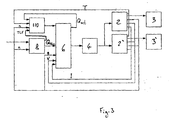
- FIG. 3 shows a block diagram of a group drive 101 according to one aspect of the present invention in which like reference numerals are used to denote similar items to those of Figure 2. The same numerals will be used throughout the present text.
- a flux reduction unit 110 is additionally provided.
- Flux reduction unit 110 receives a number of inputs. These include a signal T representative of motor temperature. This may be the temperature as measured in the stator windings or may be derived indirectly by other means. Flux reduction unit 110 further receives inputs of shaft rotation speed n, a traction control flag TCF from the traction control unit 8 as a flag that the traction control unit 8 is operative to reduce traction and a signal for the actual torque Q act from the inverter control unit 6, as calculated by the motor model provided therein.
- TCF traction control flag
- the flux reduction unit 110 includes a processor which assesses the input values T, n, TCF and Q act and determines for each value whether they represent a factors indicative of the onset of counter-phase vibration.
- T may be considered a factor if it is below 50° C
- n may be considered a factor if it represents a stator frequency below 15Hz
- TCF may be a factor if it is active
- Q act may be a factor if it is less than 70% of Q nom .
- FIG 4 shows an alternative arrangement for a flux reduction unit 210 according to an alternative embodiment of the preset invention.
- Flux reduction unit 210 includes a number of reference units 215-219 and a number of comparators 221 - 225. As in the previous embodiment of Figure 3, flux reduction unit receives a number of inputs from other elements of the group drive 1.
- T a value representative of the temperature of the motors, which can be provided as an average temperatue of the stator windings
- stator frequency (as an alternative to rotor speed n in Figure 3) may be derived from the signals S supplied by the inverter control unit 6
- dQ/d ⁇ v which gives the gradient of the wheel slip - traction characteristic and may be calculated from data provided by the inverter control unit 6 and the traction control unit 8
- torque Q and the traction control flag TCF mentioned above.
- the signal T and a value T ref stored in reference unit 215 are compared in comparator 221. If T is less than T ref then output 231 goes high. Similarily, signal f and a value f max stored in reference unit 216 are compared in comparator 222. If f is less than f max then output 232 goes high. Signal f is also compared in comparator 223 with a value f min stored reference unit 217. If f is more than f min then output 233 goes high. Signals dQ/d ⁇ v and Q are similarly compared with reference values stored in reference units 218 and 219 and comparators 224 and 225 issue high signal 234 and 235 respectively when the signals are below the reference values.
- the outputs 231- 235 and a signal 236 set by the TCF are provided as inputs to a logical AND gate 240. If all the inputs to the AND gate 240 are high, a flux reduction signal 242 is output to a flux reduction controller 250.
- Flux reduction controller applies a step reduction in the value of ⁇ nom applied as input to inverter control unit 6. This step reduction may be preset at a value of e.g. 80% of ⁇ nom and may also be related to the value of Q ref stored in comparator 219. By this means, if torque Q is sufficiently below the set point, a reduction in flux of e.g. 20% will not cause the phase current to exceed its maximum value.
- a hysteresis device 252 is located between AND gate 240 and flux reduction controller 250.
- Hysteresis device 252 is intended to prevent flux reduction controller switching in and out under operating conditions which are close to the limits given by reference units 215 to 219. This is particularly important in the case of a large number of inputs to AND gate 240, since a change in any one of those inputs could cause flux reduction signal 242 to switch.
- the hysteresis device may be temporal, requiring a certain time between switchings, or may be signal controlled, e.g. requiring more than one of the outputs 231-235 and TCF signal 236 to go low before the input to flux reduction controller 250 goes low.
- the motor temperature signal T could be provided as an AND combination of the individual motors 2, 2' wherein the signal would only be high if both motors were below the reference temperature.
- the signals TCF and dQ/d ⁇ v could be combined in an OR gate. It could also be desirable to configure AND gate 240 to go high when a certain number of the 6 inputs are high.
- various other inputs could also be included depending upon their influence on the onset of vibrations.
- the signal for torque Q may be substituted by e.g using other measurements representative of traction.
- the flux reduction controller 250 may provide a simple step reduction in flux.
- the flux reduction could be calculated according to the prevailing operating conditions wherein the flux reduction controller 250 is provided with further inputs of system parameters.
- Reduction of the flux serves to decrease the feedback gain of the overall transfer function and ensures greater stability even at low frequency. While not wishing to be bound by theory, it is believed that by reducing flux and increasing current in the motors 2, 2', the stator frequency will increase while the rotor frequency remains substantially constant. This means that the electrical slip within each of the motors 2, 2' will be greater, providing a less rigid coupling between the two inertial masses provided by the mechanical drives.
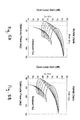
- Figure 5A illustrates the behaviour for different operational frequencies from 5 to 20Hz.
- Figure 5B illustrates the same operational frequencies but under conditions of reduced flux.
Landscapes
- Engineering & Computer Science (AREA)
- General Engineering & Computer Science (AREA)
- Acoustics & Sound (AREA)
- Aviation & Aerospace Engineering (AREA)
- Mechanical Engineering (AREA)
- Physics & Mathematics (AREA)
- Control Of Multiple Motors (AREA)
- Control Of Electric Motors In General (AREA)
- Electric Propulsion And Braking For Vehicles (AREA)
- Pressure Welding/Diffusion-Bonding (AREA)
- Detergent Compositions (AREA)
- Valve Device For Special Equipments (AREA)
- Moving Of Heads (AREA)
- Compositions Of Oxide Ceramics (AREA)
- Diaphragms For Electromechanical Transducers (AREA)
- Registering, Tensioning, Guiding Webs, And Rollers Therefor (AREA)
- Tires In General (AREA)
Priority Applications (1)
| Application Number | Priority Date | Filing Date | Title |
|---|---|---|---|
| PL04252011T PL1473485T3 (pl) | 2003-04-04 | 2004-04-02 | Zmniejszanie drgań przeciwsobnych |
Applications Claiming Priority (2)
| Application Number | Priority Date | Filing Date | Title |
|---|---|---|---|
| GB0307819 | 2003-04-04 | ||
| GBGB0307819.3A GB0307819D0 (en) | 2003-04-04 | 2003-04-04 | Reducing counter-phase vibrations |
Publications (3)
| Publication Number | Publication Date |
|---|---|
| EP1473485A2 true EP1473485A2 (fr) | 2004-11-03 |
| EP1473485A3 EP1473485A3 (fr) | 2005-01-12 |
| EP1473485B1 EP1473485B1 (fr) | 2006-06-14 |
Family
ID=9956193
Family Applications (1)
| Application Number | Title | Priority Date | Filing Date |
|---|---|---|---|
| EP04252011A Expired - Lifetime EP1473485B1 (fr) | 2003-04-04 | 2004-04-02 | Réduction des vibrations de grippage |
Country Status (7)
| Country | Link |
|---|---|
| EP (1) | EP1473485B1 (fr) |
| AT (1) | ATE330145T1 (fr) |
| DE (1) | DE602004001162T2 (fr) |
| DK (1) | DK1473485T3 (fr) |
| GB (1) | GB0307819D0 (fr) |
| PL (1) | PL1473485T3 (fr) |
| PT (1) | PT1473485E (fr) |
Cited By (2)
| Publication number | Priority date | Publication date | Assignee | Title |
|---|---|---|---|---|
| EP2940440A1 (fr) | 2014-04-30 | 2015-11-04 | Bombardier Transportation GmbH | Identification de la présence d'un état de vibration en résonance potentiellement destructeur d'un dispositif mécanique |
| IT201700102369A1 (it) * | 2017-09-13 | 2019-03-13 | Faiveley Transport Italia Spa | Sistema per il controllo di frenatura di servizio e di emergenza per almeno un veicolo ferroviario. |
Families Citing this family (2)
| Publication number | Priority date | Publication date | Assignee | Title |
|---|---|---|---|---|
| DE102012221856A1 (de) * | 2012-11-29 | 2014-06-05 | Leonhard Weiss Gmbh & Co. Kg | System und Verfahren zur Erfassung einer Flachstellenbildung an zumindest einem Radreifen |
| DE102015213929A1 (de) | 2015-07-23 | 2017-01-26 | Siemens Aktiengesellschaft | Schienenfahrzeug mit einer Behandlungseinrichtung zur Schienentrocknung |
Family Cites Families (6)
| Publication number | Priority date | Publication date | Assignee | Title |
|---|---|---|---|---|
| GB326857A (en) * | 1928-10-19 | 1930-03-19 | British Thomson Houston Co Ltd | Improvements in and relating to means for reducing vibration due to reciprocating machinery and apparatus therefor |
| US2265933A (en) * | 1938-06-16 | 1941-12-09 | Budd Edward G Mfg Co | Electric drive |
| JPH04248301A (ja) * | 1991-01-21 | 1992-09-03 | Hitachi Ltd | 電気車の制御装置 |
| DE19727507A1 (de) * | 1997-06-30 | 1999-01-07 | Abb Daimler Benz Transp | Regelung für einen Antrieb mit einem Asynchronmotor |
| DE19829778A1 (de) * | 1998-07-03 | 2000-01-05 | Abb Daimler Benz Transp | Traktionsantrieb mit Asynchronmotoren |
| JP3760280B2 (ja) * | 2001-08-29 | 2006-03-29 | 株式会社日立製作所 | 直流機器及びこれを用いた車両 |
-
2003
- 2003-04-04 GB GBGB0307819.3A patent/GB0307819D0/en not_active Ceased
-
2004
- 2004-04-02 AT AT04252011T patent/ATE330145T1/de active
- 2004-04-02 EP EP04252011A patent/EP1473485B1/fr not_active Expired - Lifetime
- 2004-04-02 DK DK04252011T patent/DK1473485T3/da active
- 2004-04-02 PL PL04252011T patent/PL1473485T3/pl unknown
- 2004-04-02 PT PT04252011T patent/PT1473485E/pt unknown
- 2004-04-02 DE DE602004001162T patent/DE602004001162T2/de not_active Expired - Lifetime
Cited By (7)
| Publication number | Priority date | Publication date | Assignee | Title |
|---|---|---|---|---|
| EP2940440A1 (fr) | 2014-04-30 | 2015-11-04 | Bombardier Transportation GmbH | Identification de la présence d'un état de vibration en résonance potentiellement destructeur d'un dispositif mécanique |
| IT201700102369A1 (it) * | 2017-09-13 | 2019-03-13 | Faiveley Transport Italia Spa | Sistema per il controllo di frenatura di servizio e di emergenza per almeno un veicolo ferroviario. |
| WO2019053599A1 (fr) * | 2017-09-13 | 2019-03-21 | Faiveley Transport Italia S.P.A. | Système de commande de freinage de service et d'urgence pour au moins un véhicule ferroviaire |
| CN111417552A (zh) * | 2017-09-13 | 2020-07-14 | 法伊韦利传送器意大利有限公司 | 用于至少一个铁路车辆的行车和紧急制动控制系统 |
| EP3681772B1 (fr) | 2017-09-13 | 2021-11-10 | Faiveley Transport Italia S.p.A. | Système de commande de freinage de service et d'urgence pour au moins un véhicule ferroviaire |
| CN111417552B (zh) * | 2017-09-13 | 2022-06-28 | 法伊韦利传送器意大利有限公司 | 用于至少一个铁路车辆的行车和紧急制动控制系统 |
| US11654876B2 (en) | 2017-09-13 | 2023-05-23 | Faiveley Transport Italia S.P.A. | Braking control system |
Also Published As
| Publication number | Publication date |
|---|---|
| DE602004001162D1 (de) | 2006-07-27 |
| PT1473485E (pt) | 2006-10-31 |
| DK1473485T3 (da) | 2006-10-09 |
| EP1473485B1 (fr) | 2006-06-14 |
| ATE330145T1 (de) | 2006-07-15 |
| GB0307819D0 (en) | 2003-05-07 |
| DE602004001162T2 (de) | 2007-04-26 |
| EP1473485A3 (fr) | 2005-01-12 |
| PL1473485T3 (pl) | 2006-11-30 |
Similar Documents
| Publication | Publication Date | Title |
|---|---|---|
| US6208097B1 (en) | Traction vehicle adhesion control system without ground speed measurement | |
| JP4297971B2 (ja) | 電動機制御装置 | |
| US8988016B2 (en) | System and method for traction motor control | |
| US5389749A (en) | Elevator system | |
| US6163121A (en) | Torque maximization and vibration control for AC locomotives | |
| AU676807B2 (en) | Control apparatus for electric vehicles | |
| JPH07106007B2 (ja) | 鉄道車両の粘着制御装置 | |
| JPWO2009037740A1 (ja) | 電気車用制御装置 | |
| US6028402A (en) | Automatic rail characterization for adhesion system evaluation for AC locomotives | |
| US6020714A (en) | Control system for a drive having an asynchronous motor | |
| CN112737421A (zh) | 一种用于控制电动机减速的方法及系统 | |
| EP1473485B1 (fr) | Réduction des vibrations de grippage | |
| WO2013114571A1 (fr) | Dispositif de commande de véhicule | |
| JP6730057B2 (ja) | 電気車制御装置 | |
| JPS631306A (ja) | チヨツパ制御方式 | |
| EP3402067B1 (fr) | Dispositif d'entraînement de moteur | |
| RU2428326C1 (ru) | Способ управления асинхронными тяговыми двигателями, подключенными параллельно к одному инвертору | |
| CA2298931C (fr) | Systeme de regulation de couple comprenant un transformateur de couple a repartition d'effort de traction amelioree | |
| JP4313493B2 (ja) | 電気鉄道車両セットの摩擦力を監視する装置 | |
| JP6147380B2 (ja) | ハイブリッド車両の発電機制御装置 | |
| RU96071U1 (ru) | Устройство управления асинхронными тяговыми двигателями, подключенными параллельно к одному инвертору | |
| KR20090061478A (ko) | 모터 제어 장치 및 그 제어 방법 | |
| JPH0454801A (ja) | 電気車制御装置 | |
| JPH07322406A (ja) | 電気車の制御装置 | |
| JPH07222309A (ja) | 電動車両の電気モータ制御装置 |
Legal Events
| Date | Code | Title | Description |
|---|---|---|---|
| PUAI | Public reference made under article 153(3) epc to a published international application that has entered the european phase |
Free format text: ORIGINAL CODE: 0009012 |
|
| AK | Designated contracting states |
Kind code of ref document: A2 Designated state(s): AT BE BG CH CY CZ DE DK EE ES FI FR GB GR HU IE IT LI LU MC NL PL PT RO SE SI SK TR |
|
| AX | Request for extension of the european patent |
Extension state: AL HR LT LV MK |
|
| PUAL | Search report despatched |
Free format text: ORIGINAL CODE: 0009013 |
|
| AK | Designated contracting states |
Kind code of ref document: A3 Designated state(s): AT BE BG CH CY CZ DE DK EE ES FI FR GB GR HU IE IT LI LU MC NL PL PT RO SE SI SK TR |
|
| AX | Request for extension of the european patent |
Extension state: AL HR LT LV MK |
|
| 17P | Request for examination filed |
Effective date: 20050712 |
|
| AKX | Designation fees paid |
Designated state(s): AT BE BG CH CY CZ DE DK EE ES FI FR GB GR HU IE IT LI LU MC NL PL PT RO SE SI SK TR |
|
| GRAP | Despatch of communication of intention to grant a patent |
Free format text: ORIGINAL CODE: EPIDOSNIGR1 |
|
| GRAS | Grant fee paid |
Free format text: ORIGINAL CODE: EPIDOSNIGR3 |
|
| GRAA | (expected) grant |
Free format text: ORIGINAL CODE: 0009210 |
|
| AK | Designated contracting states |
Kind code of ref document: B1 Designated state(s): AT BE BG CH CY CZ DE DK EE ES FI FR GB GR HU IE IT LI LU MC NL PL PT RO SE SI SK TR |
|
| PG25 | Lapsed in a contracting state [announced via postgrant information from national office to epo] |
Ref country code: IT Free format text: LAPSE BECAUSE OF FAILURE TO SUBMIT A TRANSLATION OF THE DESCRIPTION OR TO PAY THE FEE WITHIN THE PRESCRIBED TIME-LIMIT;WARNING: LAPSES OF ITALIAN PATENTS WITH EFFECTIVE DATE BEFORE 2007 MAY HAVE OCCURRED AT ANY TIME BEFORE 2007. THE CORRECT EFFECTIVE DATE MAY BE DIFFERENT FROM THE ONE RECORDED. Effective date: 20060614 Ref country code: SI Free format text: LAPSE BECAUSE OF FAILURE TO SUBMIT A TRANSLATION OF THE DESCRIPTION OR TO PAY THE FEE WITHIN THE PRESCRIBED TIME-LIMIT Effective date: 20060614 Ref country code: RO Free format text: LAPSE BECAUSE OF FAILURE TO SUBMIT A TRANSLATION OF THE DESCRIPTION OR TO PAY THE FEE WITHIN THE PRESCRIBED TIME-LIMIT Effective date: 20060614 Ref country code: SK Free format text: LAPSE BECAUSE OF FAILURE TO SUBMIT A TRANSLATION OF THE DESCRIPTION OR TO PAY THE FEE WITHIN THE PRESCRIBED TIME-LIMIT Effective date: 20060614 |
|
| REG | Reference to a national code |
Ref country code: GB Ref legal event code: FG4D |
|
| REG | Reference to a national code |
Ref country code: CH Ref legal event code: EP |
|
| REG | Reference to a national code |
Ref country code: IE Ref legal event code: FG4D |
|
| REF | Corresponds to: |
Ref document number: 602004001162 Country of ref document: DE Date of ref document: 20060727 Kind code of ref document: P |
|
| PG25 | Lapsed in a contracting state [announced via postgrant information from national office to epo] |
Ref country code: ES Free format text: LAPSE BECAUSE OF FAILURE TO SUBMIT A TRANSLATION OF THE DESCRIPTION OR TO PAY THE FEE WITHIN THE PRESCRIBED TIME-LIMIT Effective date: 20060925 |
|
| REG | Reference to a national code |
Ref country code: CH Ref legal event code: NV Representative=s name: ABREMA AGENCE BREVETS ET MARQUES GANGUILLET & HUMP |
|
| REG | Reference to a national code |
Ref country code: SE Ref legal event code: TRGR |
|
| REG | Reference to a national code |
Ref country code: DK Ref legal event code: T3 |
|
| REG | Reference to a national code |
Ref country code: PT Ref legal event code: SC4A Effective date: 20060906 |
|
| REG | Reference to a national code |
Ref country code: GR Ref legal event code: EP Ref document number: 20060403084 Country of ref document: GR |
|
| REG | Reference to a national code |
Ref country code: HU Ref legal event code: AG4A Ref document number: E000740 Country of ref document: HU |
|
| ET | Fr: translation filed | ||
| PLBI | Opposition filed |
Free format text: ORIGINAL CODE: 0009260 |
|
| PLAX | Notice of opposition and request to file observation + time limit sent |
Free format text: ORIGINAL CODE: EPIDOSNOBS2 |
|
| 26 | Opposition filed |
Opponent name: SIEMENS AG CT IP TS Effective date: 20070313 |
|
| PLAX | Notice of opposition and request to file observation + time limit sent |
Free format text: ORIGINAL CODE: EPIDOSNOBS2 |
|
| NLR1 | Nl: opposition has been filed with the epo |
Opponent name: SIEMENS AG CT IP TS |
|
| PLAF | Information modified related to communication of a notice of opposition and request to file observations + time limit |
Free format text: ORIGINAL CODE: EPIDOSCOBS2 |
|
| PLBB | Reply of patent proprietor to notice(s) of opposition received |
Free format text: ORIGINAL CODE: EPIDOSNOBS3 |
|
| PG25 | Lapsed in a contracting state [announced via postgrant information from national office to epo] |
Ref country code: IE Free format text: LAPSE BECAUSE OF NON-PAYMENT OF DUE FEES Effective date: 20070402 |
|
| PLAB | Opposition data, opponent's data or that of the opponent's representative modified |
Free format text: ORIGINAL CODE: 0009299OPPO |
|
| PG25 | Lapsed in a contracting state [announced via postgrant information from national office to epo] |
Ref country code: BG Free format text: LAPSE BECAUSE OF FAILURE TO SUBMIT A TRANSLATION OF THE DESCRIPTION OR TO PAY THE FEE WITHIN THE PRESCRIBED TIME-LIMIT Effective date: 20060914 |
|
| PG25 | Lapsed in a contracting state [announced via postgrant information from national office to epo] |
Ref country code: EE Free format text: LAPSE BECAUSE OF FAILURE TO SUBMIT A TRANSLATION OF THE DESCRIPTION OR TO PAY THE FEE WITHIN THE PRESCRIBED TIME-LIMIT Effective date: 20060614 |
|
| PGRI | Patent reinstated in contracting state [announced from national office to epo] |
Ref country code: IT Effective date: 20080601 |
|
| PG25 | Lapsed in a contracting state [announced via postgrant information from national office to epo] |
Ref country code: MC Free format text: LAPSE BECAUSE OF NON-PAYMENT OF DUE FEES Effective date: 20070430 |
|
| PG25 | Lapsed in a contracting state [announced via postgrant information from national office to epo] |
Ref country code: LU Free format text: LAPSE BECAUSE OF NON-PAYMENT OF DUE FEES Effective date: 20070402 Ref country code: CY Free format text: LAPSE BECAUSE OF FAILURE TO SUBMIT A TRANSLATION OF THE DESCRIPTION OR TO PAY THE FEE WITHIN THE PRESCRIBED TIME-LIMIT Effective date: 20060614 |
|
| PG25 | Lapsed in a contracting state [announced via postgrant information from national office to epo] |
Ref country code: TR Free format text: LAPSE BECAUSE OF FAILURE TO SUBMIT A TRANSLATION OF THE DESCRIPTION OR TO PAY THE FEE WITHIN THE PRESCRIBED TIME-LIMIT Effective date: 20060614 |
|
| PLCK | Communication despatched that opposition was rejected |
Free format text: ORIGINAL CODE: EPIDOSNREJ1 |
|
| PLBN | Opposition rejected |
Free format text: ORIGINAL CODE: 0009273 |
|
| STAA | Information on the status of an ep patent application or granted ep patent |
Free format text: STATUS: OPPOSITION REJECTED |
|
| 27O | Opposition rejected |
Effective date: 20091207 |
|
| PGFP | Annual fee paid to national office [announced via postgrant information from national office to epo] |
Ref country code: AT Payment date: 20120511 Year of fee payment: 9 |
|
| PGFP | Annual fee paid to national office [announced via postgrant information from national office to epo] |
Ref country code: CZ Payment date: 20130327 Year of fee payment: 10 |
|
| PGFP | Annual fee paid to national office [announced via postgrant information from national office to epo] |
Ref country code: PL Payment date: 20130322 Year of fee payment: 10 |
|
| PGFP | Annual fee paid to national office [announced via postgrant information from national office to epo] |
Ref country code: CH Payment date: 20130422 Year of fee payment: 10 Ref country code: BE Payment date: 20130418 Year of fee payment: 10 Ref country code: GB Payment date: 20130418 Year of fee payment: 10 Ref country code: DE Payment date: 20130419 Year of fee payment: 10 Ref country code: SE Payment date: 20130418 Year of fee payment: 10 Ref country code: DK Payment date: 20130418 Year of fee payment: 10 |
|
| PGFP | Annual fee paid to national office [announced via postgrant information from national office to epo] |
Ref country code: IT Payment date: 20130422 Year of fee payment: 10 Ref country code: FI Payment date: 20130411 Year of fee payment: 10 Ref country code: PT Payment date: 20130401 Year of fee payment: 10 Ref country code: GR Payment date: 20130419 Year of fee payment: 10 Ref country code: NL Payment date: 20130418 Year of fee payment: 10 Ref country code: FR Payment date: 20130515 Year of fee payment: 10 Ref country code: HU Payment date: 20130430 Year of fee payment: 10 |
|
| REG | Reference to a national code |
Ref country code: PT Ref legal event code: MM4A Free format text: LAPSE DUE TO NON-PAYMENT OF FEES Effective date: 20141002 |
|
| PG25 | Lapsed in a contracting state [announced via postgrant information from national office to epo] |
Ref country code: CZ Free format text: LAPSE BECAUSE OF NON-PAYMENT OF DUE FEES Effective date: 20140402 |
|
| REG | Reference to a national code |
Ref country code: DE Ref legal event code: R119 Ref document number: 602004001162 Country of ref document: DE |
|
| REG | Reference to a national code |
Ref country code: DK Ref legal event code: EBP Effective date: 20140430 |
|
| REG | Reference to a national code |
Ref country code: NL Ref legal event code: V1 Effective date: 20141101 |
|
| REG | Reference to a national code |
Ref country code: CH Ref legal event code: PL |
|
| REG | Reference to a national code |
Ref country code: SE Ref legal event code: EUG |
|
| REG | Reference to a national code |
Ref country code: AT Ref legal event code: MM01 Ref document number: 330145 Country of ref document: AT Kind code of ref document: T Effective date: 20140402 |
|
| GBPC | Gb: european patent ceased through non-payment of renewal fee |
Effective date: 20140402 |
|
| REG | Reference to a national code |
Ref country code: GR Ref legal event code: ML Ref document number: 20060403084 Country of ref document: GR Effective date: 20141104 |
|
| REG | Reference to a national code |
Ref country code: DE Ref legal event code: R119 Ref document number: 602004001162 Country of ref document: DE Effective date: 20141101 |
|
| REG | Reference to a national code |
Ref country code: FR Ref legal event code: ST Effective date: 20141231 |
|
| PG25 | Lapsed in a contracting state [announced via postgrant information from national office to epo] |
Ref country code: FI Free format text: LAPSE BECAUSE OF NON-PAYMENT OF DUE FEES Effective date: 20140402 Ref country code: PT Free format text: LAPSE BECAUSE OF NON-PAYMENT OF DUE FEES Effective date: 20141002 Ref country code: CH Free format text: LAPSE BECAUSE OF NON-PAYMENT OF DUE FEES Effective date: 20140430 Ref country code: DE Free format text: LAPSE BECAUSE OF NON-PAYMENT OF DUE FEES Effective date: 20141101 Ref country code: GR Free format text: LAPSE BECAUSE OF NON-PAYMENT OF DUE FEES Effective date: 20141104 Ref country code: GB Free format text: LAPSE BECAUSE OF NON-PAYMENT OF DUE FEES Effective date: 20140402 Ref country code: SE Free format text: LAPSE BECAUSE OF NON-PAYMENT OF DUE FEES Effective date: 20140403 Ref country code: LI Free format text: LAPSE BECAUSE OF NON-PAYMENT OF DUE FEES Effective date: 20140430 |
|
| PG25 | Lapsed in a contracting state [announced via postgrant information from national office to epo] |
Ref country code: NL Free format text: LAPSE BECAUSE OF NON-PAYMENT OF DUE FEES Effective date: 20141101 Ref country code: AT Free format text: LAPSE BECAUSE OF NON-PAYMENT OF DUE FEES Effective date: 20140402 Ref country code: HU Free format text: LAPSE BECAUSE OF NON-PAYMENT OF DUE FEES Effective date: 20140403 Ref country code: FR Free format text: LAPSE BECAUSE OF NON-PAYMENT OF DUE FEES Effective date: 20140430 |
|
| PG25 | Lapsed in a contracting state [announced via postgrant information from national office to epo] |
Ref country code: IT Free format text: LAPSE BECAUSE OF FAILURE TO SUBMIT A TRANSLATION OF THE DESCRIPTION OR TO PAY THE FEE WITHIN THE PRESCRIBED TIME-LIMIT Effective date: 20140402 |
|
| PG25 | Lapsed in a contracting state [announced via postgrant information from national office to epo] |
Ref country code: DK Free format text: LAPSE BECAUSE OF NON-PAYMENT OF DUE FEES Effective date: 20140430 |
|
| REG | Reference to a national code |
Ref country code: PL Ref legal event code: LAPE |
|
| PG25 | Lapsed in a contracting state [announced via postgrant information from national office to epo] |
Ref country code: PL Free format text: LAPSE BECAUSE OF NON-PAYMENT OF DUE FEES Effective date: 20140402 |
|
| PG25 | Lapsed in a contracting state [announced via postgrant information from national office to epo] |
Ref country code: BE Free format text: LAPSE BECAUSE OF NON-PAYMENT OF DUE FEES Effective date: 20140430 |