EP1473799B1 - Mehrzonensatellit mit Leuchtzonensteuerung - Google Patents
Mehrzonensatellit mit Leuchtzonensteuerung Download PDFInfo
- Publication number
- EP1473799B1 EP1473799B1 EP04291108.1A EP04291108A EP1473799B1 EP 1473799 B1 EP1473799 B1 EP 1473799B1 EP 04291108 A EP04291108 A EP 04291108A EP 1473799 B1 EP1473799 B1 EP 1473799B1
- Authority
- EP
- European Patent Office
- Prior art keywords
- chosen
- amplitude
- receive
- mti
- processing means
- Prior art date
- Legal status (The legal status is an assumption and is not a legal conclusion. Google has not performed a legal analysis and makes no representation as to the accuracy of the status listed.)
- Expired - Lifetime
Links
- 238000012545 processing Methods 0.000 claims description 29
- 230000008878 coupling Effects 0.000 claims description 16
- 238000010168 coupling process Methods 0.000 claims description 16
- 238000005859 coupling reaction Methods 0.000 claims description 16
- 230000005540 biological transmission Effects 0.000 description 48
- 230000010287 polarization Effects 0.000 description 6
- 238000005286 illumination Methods 0.000 description 5
- 238000005259 measurement Methods 0.000 description 5
- 239000013256 coordination polymer Substances 0.000 description 4
- 239000006185 dispersion Substances 0.000 description 4
- 230000002093 peripheral effect Effects 0.000 description 4
- 238000004891 communication Methods 0.000 description 3
- 230000002829 reductive effect Effects 0.000 description 3
- 230000003068 static effect Effects 0.000 description 3
- 238000006073 displacement reaction Methods 0.000 description 2
- 238000005516 engineering process Methods 0.000 description 2
- 238000000605 extraction Methods 0.000 description 2
- 230000000670 limiting effect Effects 0.000 description 2
- 230000007246 mechanism Effects 0.000 description 2
- 239000007787 solid Substances 0.000 description 2
- 238000011144 upstream manufacturing Methods 0.000 description 2
- 230000004913 activation Effects 0.000 description 1
- 238000013461 design Methods 0.000 description 1
- 238000011161 development Methods 0.000 description 1
- 238000010586 diagram Methods 0.000 description 1
- 230000009977 dual effect Effects 0.000 description 1
- 238000005265 energy consumption Methods 0.000 description 1
- 230000001747 exhibiting effect Effects 0.000 description 1
- 230000006872 improvement Effects 0.000 description 1
- 238000002347 injection Methods 0.000 description 1
- 239000007924 injection Substances 0.000 description 1
- 230000002452 interceptive effect Effects 0.000 description 1
- 238000012544 monitoring process Methods 0.000 description 1
- 238000005457 optimization Methods 0.000 description 1
- 230000036961 partial effect Effects 0.000 description 1
- 230000005855 radiation Effects 0.000 description 1
- 230000009467 reduction Effects 0.000 description 1
- 239000000523 sample Substances 0.000 description 1
Images


Classifications
-
- H—ELECTRICITY
- H01—ELECTRIC ELEMENTS
- H01Q—ANTENNAS, i.e. RADIO AERIALS
- H01Q1/00—Details of, or arrangements associated with, antennas
- H01Q1/27—Adaptation for use in or on movable bodies
- H01Q1/28—Adaptation for use in or on aircraft, missiles, satellites, or balloons
- H01Q1/288—Satellite antennas
-
- H—ELECTRICITY
- H01—ELECTRIC ELEMENTS
- H01Q—ANTENNAS, i.e. RADIO AERIALS
- H01Q3/00—Arrangements for changing or varying the orientation or the shape of the directional pattern of the waves radiated from an antenna or antenna system
- H01Q3/26—Arrangements for changing or varying the orientation or the shape of the directional pattern of the waves radiated from an antenna or antenna system varying the relative phase or relative amplitude of energisation between two or more active radiating elements; varying the distribution of energy across a radiating aperture
- H01Q3/28—Arrangements for changing or varying the orientation or the shape of the directional pattern of the waves radiated from an antenna or antenna system varying the relative phase or relative amplitude of energisation between two or more active radiating elements; varying the distribution of energy across a radiating aperture varying the amplitude
Definitions
- the invention relates to the field of satellite communications, and more particularly that of monitoring the coverage of multiple geographic areas (or “spots”) by communications satellites.
- multi-zone hopping (or “beam hopping”).
- This coverage schematically consists of providing continuous multi-zone coverage (in transmission and / or in reception) with passive antennas, the zones being grouped into cells within each of which a single zone, called active, is covered at any time, and the different areas of the cells being active one after the other, periodically.
- This type of coverage makes it possible in particular to allocate the entire frequency band available over a part (active) of all the zones during a given period.
- a first arrangement consists in using first, second, third and fourth transmit / receive antennas (dual bands) containing sources respectively defining first, second, third and fourth zones, each cell then being made up of a first, a second, a third and a fourth zones.
- the mesh available at the level of the sources is large enough to allow the use of sources with a large aperture (typically 4 to 6 ⁇ ) and therefore very directive. This makes it possible to obtain very high illumination efficiencies, typically 75% to 80%.
- the antennas are dual-band, the gain at the edge of coverage (G EOC ) cannot be optimized simultaneously in transmission and reception.
- the zone hopping (or “beam hopping”) being carried out by antenna switching, the losses generated at the level of the link guides, between each source and the switch, are significant.
- a second arrangement consists in repeating the previous arrangement by doubling the number of antennas so as to have four transmitting antennas and four receiving antennas.
- the mesh being substantially identical to that of the previous arrangement, it is therefore also possible to obtain very high illumination yields, typically from 75% to 80%.
- the antennas being here optimized in each frequency band, it is therefore possible to optimize the gain at the edge of coverage (G EOC ) simultaneously in transmission and in reception.
- G EOC edge of coverage
- the use of eight antennas imposes significant layout constraints.
- the beam hopping also taking place by antenna switching, the losses generated at the level of the link guides, between each source and the switch, are significant.
- a third arrangement consists of starting from the first arrangement by reducing the number of antennas to three.
- the mesh size available is here slightly smaller than in the two previous arrangements, so that the sources have an opening of the order of 3 to 5 ⁇ and are therefore a little less directive.
- the illumination efficiency still remains very acceptable and the development constraint is greatly relaxed.
- the losses generated at the level of the link guides, between each source and the switch are significant.
- the mesh being tighter, the performance of C / l (ratio between the useful signal (C for "Carrier") and the interfering signals (I) generated by the other sources working in the same frequency band and in the same polarization as the useful zone) are degraded.
- a fourth arrangement consists in using only one transmitting antenna and one receiving antenna. Beam hopping taking place now by switching within the same antenna, the losses generated at the level of the link guides, between each source and the switch, are insignificant. However, the definition of all the zones with a single antenna imposes a very tight mesh, so that the sources have an aperture of the order of 1.2 to 1.5 ⁇ and are therefore very little directive. The illumination efficiency is then very poor (typically 35% to 40%), which imposes an oversizing of the antenna reflectors and antennas which can lead to technology problems, in particular when the satellite is operating in the frequency band. "Ka".
- the gain at the edge of coverage (G EOC ) is therefore reduced by 3 to 4 dB compared to the previous arrangements, and the “roll-off” (variation of gain over the whole of the multi-zone coverage, and more precisely the difference between the maximum gain on each zone and the EOC gain) is very high, typically of the order of 8 to 12 dB compared to the 4 to 6 dB presented by the preceding arrangements.
- the situation is substantially the same as regards the other types of multi-zone coverage and in particular in the case of multi-zone coverage by static beam deflection and multi-zone coverage by dynamic deflection of a beam.
- the documents EP1191628 and EP0683543 describe telecommunications satellites with multi-zone coverage, comprising at least one transmission and / or reception antenna comprising at least one transmission and / or reception source suitable for delivering and / or receiving a beam in a chosen direction defined by a phase of chosen value and an amplitude of chosen value.
- the object of the invention is therefore to improve the situation in terms of multi-zone coverage.
- it proposes a telecommunications satellite with multi-zone coverage according to claim 1.
- the processing means are responsible for deflecting the beam in several directions chosen as a function of a law of variation of the value of the amplitude.
- the processing means preferably comprise a first coupler installed on the main line and coupled to a first end of an auxiliary line comprising amplitude variation means, and a second coupler located on the main line between the first coupler and the module d transmission or reception and connected to a second end of the auxiliary line.
- the second coupler can be arranged in the form of an ecartometry coupler, such as for example a mode extractor (s) comprising a circular waveguide coupled to at least one rectangular waveguide via a row of slits.
- the processing means comprise a coupler implanted on the main line and coupled to at least one resonant cavity defining the amplitude.
- the processing means can comprise at least two resonant cavities each controlled by a PIN diode and having between them chosen electromagnetic couplings which define the amplitude.
- the processing means can be arranged so as to deflect the beam or the direction of reception in at least one of the directions chosen by varying the value of the amplitude and the value of the sentence.
- the deviation is then preferably carried out as a function of a law of variation of the value of the amplitude and of a law of variation of the value of the phase.
- the auxiliary line embodiment presented above, then comprises phase variation means located on said auxiliary line.
- the single coupler is coupled to at least three resonant cavities each controlled by a PIN diode and having between them chosen electromagnetic couplings defining the amplitude and of which the respective positions, relative to the coupler, define the phase.
- the transmission and / or reception antenna comprises a multiplicity of transmission and / or reception sources, each delivering a beam in a chosen direction, and first control means responsible for controlling the processing means (which are coupled to the transmission and / or reception sources) according to a chosen spatio-temporal pattern.
- the first control means can then be arranged so as to order the processing means to operate simultaneously and according to cycles of equal durations so that the satellite provides multi-zone coverage by zone hopping (or beam hopping).
- the invention finds a particularly advantageous application, although in a nonlimiting manner, in the case of transmission and / or reception of beams in the frequency bands of the “Ku” and / or “Ka” type.
- the invention relates to telecommunications satellites intended for multi-zone transmission and / or reception coverage, and more precisely to such satellites comprising at least one passive transmission antenna and / or at least one passive reception antenna. .
- Such a source of transmission and / or reception Si comprises a transmission and / or reception module Ri, such as for example a transponder (such as an HPA for “high power amplifier” in transmission or such as a LNA for "low noise amplifier” in reception), and a transmitter and / or receiver Ci, such as for example a horn, coupled to the transmission and / or reception module Ri by a main line LPi, such as for example a guide waveform, equipped with an MTi processing module.
- Ri such as for example a transponder (such as an HPA for “high power amplifier” in transmission or such as a LNA for "low noise amplifier” in reception)
- a transmitter and / or receiver Ci such as for example a horn
- This processing module MTi is responsible for deflecting the beam (or the direction of reception), which the horn Ci which is associated with it must send (and / or receive), in at least one chosen direction which differs from the direction associated with the mode.
- standard propagation of the transmission and / or reception channel i (or source Si) which is defined by an amplitude A and by a phase ⁇ .
- the deviation is obtained at least by a variation ⁇ of the value of the amplitude A of the beam transmitted or received by a transmission and / or reception module R. But, as illustrated on figure 2 , the deviation can be obtained both by a variation ⁇ of the value of the amplitude A and by a variation of the value of the phase ⁇ .
- the dotted circle Z, of center Cnd materializes the coverage of an area by a beam transmitted or received, without processing (or deviation), by a horn Ci of a transmission and / or reception antenna with a " angular dispersion ⁇ , while the solid circle Z ′, with center Cd materializes the coverage of an area by a deviated beam emitted or received by the same horn Ci with the same angular dispersion ⁇ .
- the maximum deviation is limited to the value of ⁇ , which corresponds to the width of the lobe at 3 dB.
- the TMi processing module can be arranged in different ways.
- a first way can for example consist in installing on the main line LP of a transmission and / or reception path one or more resonant cavities arranged so as to vary the amplitude of the signals, as well as possibly their phase.
- the processing module TM comprises a coupler CP installed on the main line LP and coupled to a single resonant cavity CR.
- the electromagnetic coupling between the coupler CP and the cavity CR makes it possible to excite one or two modes of a higher order than that of the telecommunications signal to be transmitted or received, delivered by the transmission and / or reception module R, this which induces a deviation of the main transmission and / or reception lobe of the horn C, and consequently of the beam to be transmitted or of the direction of reception of the beam to be received, which beam contains said telecommunication signal.
- This embodiment which allows only one deflection is particularly well suited to situations in which the deflection of the beam is static.
- the invention makes it possible to replace one or more spots while also offering more directive sources, as illustrated on figure 4 .
- the dotted circles Z1 to Z4 materialize four contiguous sources, while the solid line circles Z'1 to Z'4 materialize the final positions of the zones (or spots) covered by said sources after treatment (the spots corresponding to the sources without treatment are circles concentric with the dotted circles Z1 to Z4 and of diameters equivalent to those of the solid circles Z'1 to Z'4, and the arrows materialize the displacements d2 to d4 of the centers of the zones Z2 to Z4).
- This example corresponds in particular to the case of satellites that use four 1.74 ° S-band (2500 MHz) sources.
- the invention makes it possible to replace either a 9-meter antenna equipped with at least twelve sources and a BFN (for “Beam Forming Network”) - device making it possible to apply amplitude and phase laws on all the sources to generate four spots; we therefore use three to four sources to generate each spot and some sources can be used several times), i.e. three 5-meter antennas equipped with four sources, by a five-meter antenna equipped with four highly directional sources. This results in an improvement in the gain, an optimization of the roll-off and a notable reduction in the bulk.
- BFN for “Beam Forming Network”
- This embodiment also corresponds to situations requiring the coverage of adjacent areas with overlap. Such a situation corresponds in particular to satellites using four antennas, one of which provides coverage using spots of Ku and Ka types.
- Such satellites generally provide coverage for nine Ka-band areas and four Ku-band areas.
- the Ku band corresponds, in reception, substantially to the interval [13.7 GHz, 15.6 GHz] and, in transmission, substantially to the interval [10.7 GHz, 12.8 GHz].
- the Ka band corresponds, in reception, substantially to the interval [27.5 GHz, 30 GHz] and, in transmission, substantially to the interval [18.2 GHz, 20.2 GHz].
- the invention makes it possible to use very directive Ka and Ku sources, and consequently to significantly improve the gain and the C / l ratio, to greatly optimize the roll-off and to significantly reduce the consumption of power.
- This embodiment also corresponds to situations requiring a dynamic deflection of a beam (also called “theater displacement”).
- This situation can arise when using a beam exhibiting an angular dispersion of between approximately 1.6 ° and 3.2 ° making it possible to cover an area of 1000 to 2000 kilometers. This is particularly the case during certain events such as the Olympic Games.
- the invention here makes it possible to reposition a beam electronically and quickly at will, without having to mechanically move the satellite, as is currently the case, which reduces energy consumption and significantly improves positioning accuracy and its reliability. speed.
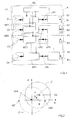
- a variant of this embodiment using a single permanently active resonant cavity may consist, as illustrated in Figure figure 5 , to use on each transmission and / or reception channel i (or source Si) a processing module MT comprising a coupler CP installed on the main line LP and coupled to at least two resonant cavities CR1, CR2 each controlled by a PIN diode DP1, DP2 and having between them electromagnetic couplings chosen so as to vary the amplitude as well as possibly the phase.
- the electromagnetic coupling between the cavities CR1 and CR2, via the coupler CP, makes it possible to excite one or two modes of order higher than the fundamental mode of the telecommunication signal to be transmitted, delivered by the transmission and / or reception module R , which induces a deviation of the main emission lobe of the horn C, and consequently of the beam to be emitted or of the direction of reception. More precisely, the amplitude ⁇ of the deviation is fixed by the coupling between the resonant cavities, while the variation in the value of the phase ⁇ is fixed by the position of the resonant cavities.
- the number of possible deviations is fixed here by the number of possible combinations of activation of the different resonant cavities CR, via the associated control PIN diodes DP, which obviously depends on the number of resonant cavities used (for example four or eight).
- the MT processing module can be realized in a second way, as illustrated in the figure 6 .
- This second way consists in installing on the main line LP of a transmission and / or reception channel (or source S), on the one hand, a first coupler CP1, coupled to a first end of an auxiliary line LA comprising an amplitude attenuator AA and a phase shifter DP, and on the other hand, a second coupler CP2 (downstream of the first coupler CP1), coupled to a second end of the auxiliary line LA.
- the first coupler CP1 is arranged to take from the main line LP part of the telecommunication signal to be transmitted in the form of a beam, so as to inject it into the main line LP.
- the auxiliary line LA where it is the subject of an amplitude variation at the level of the amplitude attenuator AA, as well as possibly a phase variation at the level of the phase shifter DP, before being reinjected into the main line LP thanks to the second coupler CP2.
- the second coupler CP2 is arranged so as to generate at the input of the horn C one or two modes (for example TM01 and TE21 which make it possible to generate antisymmetric radiation patterns with an absence of signal in the axis) of a higher order in the fundamental mode of the telecommunication signal to be transmitted, delivered by the transmission module R, which induces the deflection of the beam.
- the injection of one or two higher order modes at the inlet of the horn C causes a deviation of its main emission lobe. This also applies to reception by virtue of the reciprocity theorem which applies when the elements are of passive type.
- the amplitude attenuator AA and / or the phase shifter DP can be of the variable type, when this proves to be necessary.
- a beam can be deflected in four directions.
- the processing module TM is therefore configured to vary the amplitude according to a chosen amplitude law and / or the phase according to a chosen phase law.
- phase shifter DP is omitted.
- the deviation results exclusively from a variation in amplitude.
- This embodiment like that presented previously with reference to the figure 5 , is particularly well suited, although in a non-limiting manner, to multi-zone coverage by zone hopping (or beam hopping) which is illustrated on the figures 7 and 8 .
- multi-zone (or multi-spot) coverage by beam hopping consists of forming a “cluster” or “mosaic” G of adjacent coverage zones (or spots) Z, which, preferably, partially overlap.
- Each cluster G is subdivided into cells Cel comprising the same number j of zones Zj.
- Beam hopping consists in making active, at any time, only one zone Zj of each cell Cel of a cluster G. Consequently, the zones Zj of the same cell Cel are active (or covered) one after the other. the others, periodically and preferably for identical periods equal to the jth part ⁇ T of the period, under the control of the control module MC.
- the active zones ZA of a cluster G are shown in black, while the inactive zones ZI are shown in white.
- the entire available frequency band can be allocated to an (active) part of all the zones during a given period.
- This situation corresponds, in particular, to the satellites which at each instant define around a hundred active zones ZA in the Ka band and of angular dispersion (or extension) of approximately 0.36 °.
- the same source Si now makes it possible to cover the four (or N) zones Zj of the same cell Cel by using the principle of beam deflection described above.
- the horn Ci of the source Si (or transmission and / or reception channel i) is arranged to deliver an untreated (or undeflected) beam whose center is materialized by the small black circle Fnd, and the module of processing MTi, associated with this source Si, is arranged so as to deflect the beam in four different directions which define (here) the four zones Z1 to Z4 of a cell Cel.
- the first zone (or spot) Z1 corresponds to a beam deflected along a first direction defined by an amplitude A0 and a phase ⁇ 0
- the second zone Z2 corresponds to a beam deflected along a second direction defined by an amplitude A0 / 3 and a phase ⁇ 0 + 90 °
- the third zone Z3 corresponds to a beam deflected in a third direction defined by an amplitude A0 and a phase ⁇ 0 + 180 °
- the fourth zone Z4 corresponds to a beam deflected according to a fourth direction defined by an amplitude A0 / ⁇ 3 and a phase ⁇ 0 + 270 °.
- the amplitude of deviation ⁇ 1 of the center of the beam corresponding to the first zone Z1 with respect to the reference direction defined by the center of the non-deflected beam Fnd is substantially equal to 3 ⁇ / 4
- the amplitude of deviation p2 of the center of the beam corresponding to the second zone Z2 with respect to the reference direction is approximately equal to ⁇ ⁇ 3 / 4.
- the processing module MTi of a transmission and / or reception channel i (or source Si) is therefore arranged to “switch” the beam delivered by (or the direction of reception of the beam received by) its horn Ci of one area to another.
- the beam is deflected in the first direction, so that only the first zone Z1 of the cell Ci is covered (or active).
- This situation corresponds to the upper right part of the figure 7 (T0).
- the beam is deflected in the second direction, so that only the second zone Z2 of the cell Ci is covered (or active).
- This situation corresponds to the lower right part of the figure 7 (T0 + ⁇ T).
- the beam is deflected in the third direction, so that only the third zone Z3 of the cell Ci is covered (or active). This situation corresponds to the lower left part of the figure 7 (T0 + 2 ⁇ T).
- the beam is deflected in the fourth direction, so that only the fourth zone Z4 of the cell Ci is covered (or active). This situation corresponds to the upper left part of the figure 7 (T0 + 3 ⁇ T).
- the control module MC of the transmission antenna A is arranged so as to make the processing modules MTi of each transmission channel i (or source Si) operate according to a space-time law. More preferably, the control module MC controls the processing modules MTi so that they operate synchronously, simultaneously and periodically, and that during each fraction of period ⁇ T a same zone Zj of each Cel cell is activated (or covered).
- these sources can be very directive, which makes it possible to obtain a very optimized illumination efficiency.
- this makes it possible to best optimize the G EOC gain at the edge of the cover (or EOC for “Edge Of Coverage”).
- the switching of the bearn hopping type taking place within the same antenna the losses due to the link guides are greatly reduced.
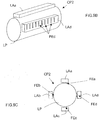
- FIG. 9A we now refer to figures 9A to 9C to describe an embodiment and operation of a second coupler CP2 that can be used on a transmission and / or reception channel of the type of those illustrated on the figures 1 and 6 .
- the second coupler CP2 is preferably a so-called “deviation measurement” coupler (or “mode extractor”), arranged to take from the main line LP, at the outlet of the. horn receiver C, the mode (s) which is (are) pursued to inject it into the first auxiliary line LA.
- the deviation measurement coupler CP2 is designed so as to define a short-circuit plane for the tracking mode (s) which will force it (s) to join the first auxiliary line LA (the standard (or fundamental) propagation mode, of the lowest order, as well as the other non-tracked modes therefore continue their journey within the main line LP).
- the deviation measurement coupler CP2 is arranged so as to extract and / or generate the modes TM01 and TE21 from the main line LP in order to inject them into the first auxiliary line LA.
- the transmission and / or reception element is here of the monobloc type. It comprises an upstream part defining a horn C and a downstream part extending the upstream part and defining a deviation measurement coupler CP2.
- the downstream part CP2 here consists, on the one hand, of a central waveguide LP, of circular section, defining the main line in which the tracked modes are extracted and / or generated, of a second part, of four peripheral waveguides LAa to LAd, of rectangular section, defining four portions of the first auxiliary line, and on the third part, four rows of coupling slots FEa to FEd, preferably of rectangular shape, ensuring the coupling between the central waveguide LP and the four peripheral waveguides LAa to LAd.
- coupling slots can be used, such as, for example, slots of circular or elliptical shape, or even cross, and the like.
- the higher order modes being pursued are therefore extracted and / or generated from the main waveguide LP by the coupling slots FEa to FEd and then injected into the peripheral waveguides LAa to LAd.
- the number of rows of slots, and therefore the number of peripheral waveguides, of the embodiment illustrated in the figures 9A to 9C are not limited to 4. This number can take any value greater than or equal to one (1). It is important to note that the number of rows does not correspond to the number of modes extracted and / or generated. It is in fact possible to use four rows of slots to extract and / or generate a single upper mode. Furthermore, the number of rows is also used to distribute the extraction and / or generation of the higher modes without disturbing the main telecommunications path. This is why we generally use rows of coupling slots with symmetry of revolution, for example four rows at 90 ° or eight rows at 45 °, etc. also consider a probe coupling when the first auxiliary line is of the coaxial type.
- TM01 Only one higher-order mode (generally TM01) is used when the polarization of the incident, or transmitted, wave is circular. Knowing the values of the amplitude and of the phase, a single mode is then sufficient to determine each time the parameters ⁇ and ⁇ described previously with reference to the figure 2 . In other words, in the case of circular polarization, by using only one mode it is possible to deflect the beam in emission (or the direction of reception) in any direction of space in the 3 dB ( ⁇ 3dB ) main lobe width limits.
- two higher order modes are used (generally the pairs (TM01 and TE21) or (orthogonal TE21 and TE21)) when the polarization of the incident or transmitted wave is linear. Knowing the values of the amplitude and of the phase of these two modes, it is in fact possible to determine each time the parameters ⁇ and ⁇ described previously with reference to the figure 2 . In other words, in the case of a linear polarization, by using two orthogonal modes, one can deflect the beam in emission (or the direction of reception) in any direction of space within the limits of width of the main lobe at 3 dB ( ⁇ 3dB ).
- the invention is not limited to the embodiments of a telecommunications satellite described above, only by way of example, but it encompasses all the variants that a person skilled in the art may envisage within the framework of the claims above. after.
Landscapes
- Physics & Mathematics (AREA)
- Engineering & Computer Science (AREA)
- Astronomy & Astrophysics (AREA)
- General Physics & Mathematics (AREA)
- Remote Sensing (AREA)
- Aviation & Aerospace Engineering (AREA)
- Variable-Direction Aerials And Aerial Arrays (AREA)
- Radio Relay Systems (AREA)
- Aerials With Secondary Devices (AREA)
Claims (8)
- Telekommunikationssatellit mit Mehrzonendeckung, umfassend mindestens eine Sende- und/oder Empfangsantenne (A), Folgendes umfassend:eine Vielzahl von Sende- und/oder Empfangsquellen (Si), welche geeignet sind, einen Strahl abzugeben und/oder zu empfangen in einer gewählten Richtung, definiert durch eine Phase eines gewählten Wertes und eine Amplitude eines gewählten Wertes,wobei jede der Sende- und/oder Empfangsquellen (Si) mit Verarbeitungsmitteln (MTi) gekoppelt ist, welche angeordnet sind, um den Strahl oder die Empfangsrichtung entsprechend mehrerer anderer Richtungen abzulenken, welche in Abhängigkeit eines Variationsgesetzes des Wertes der Amplitude gewählt werden,und erste Steuerungsmittel (MC), welche angeordnet sind, um die ersten Verarbeitungsmittel (MTi) zu steuern, welche mit den Sende- und/oder Empfangsquellen (Si) in Abhängigkeit eines gewählten räumlich-zeitlichen Schemas gekoppelt sind,wobei die Sende- und/oder Empfangsquellen (Si) eine Hauptleitung (LPi) umfassen, welche ein Speisungsmodul (Ri) mit einem Sende- und/oder Empfangsmodul (Ci) verbindet, wobei die Verarbeitungsmittel (MTi) einen Koppler (CPi) umfassen, der an der Sende- und/oder Empfangsleitung (LPi) eingebaut ist,dadurch gekennzeichnet, dassder Koppler (CPi) mit mindestens einem Resonanzhohlraum (CRi) gekoppelt ist, welcher die Amplitude durch Anregung eines oder mehrerer Modi höherer Größenordnung gegenüber dem Grundmodus des zu sendenden oder zu empfangenden Telekommunikationssignals definiert.
- Satellit nach Anspruch 1, dadurch gekennzeichnet, dass die Verarbeitungsmittel (MTi) mindestens zwei Resonanzhohlräume (CR1, CR2) umfassen, welche jeweils durch eine PIN-Diode (DP1, DP2) angesteuert werden und zwischen einander gewählte elektromagnetische Kopplungen aufweisen, welche die Amplitude definieren.
- Satellit nach einem der Ansprüche 1 bis 2, dadurch gekennzeichnet, dass die Verarbeitungsmittel (MTi) angeordnet sind, um den Strahl oder die Empfangsrichtung entsprechend mindestens einer der anderen Richtungen abzulenken, welche durch Variation des Wertes der Amplitude und des Wertes der Phase gewählt werden.
- Satellit nach Anspruch 3, dadurch gekennzeichnet, dass die Verarbeitungsmittel (MTi) angeordnet sind, um den Strahl oder die Empfangsrichtung entsprechend den anderen Richtungen abzulenken, welche in Abhängigkeit eines Variationsgesetzes des Wertes der Amplitude und eines Variationsgesetzes des Wertes der Phase gewählt werden.
- Satellit nach Anspruch 4, dadurch gekennzeichnet, dass der Koppler (CPi) mit mindestens drei Resonanzhohlräumen (CR) gekoppelt ist, welche jeweils durch eine PIN-Diode (DP) angesteuert werden und zwischen einander gewählte elektromagnetische Kopplungen aufweisen, welche die Amplitude definieren und deren jeweilige Positionen in Bezug auf den Koppler (CPi) die Phase definieren.
- Satellit nach einem der vorhergehenden Ansprüche, dadurch gekennzeichnet, dass die Verarbeitungsmittel (MTi) einer jeden Sende- und/oder Empfangsquelle (Si) angeordnet sind, um einen Strahl oder die Empfangsrichtung zyklisch entlang N unterschiedlichen Richtungen abzulenken, welche N Deckungszonen (Z1, Z2, Z3, Z4) entsprechen, wobei jeder Strahl entlang einer der N Richtungen während einer gewählten Dauer abgelenkt wird, welche dem N-ten Teil der Zyklusdauer entspricht.
- Satellit nach einem der vorhergehenden Ansprüche, dadurch gekennzeichnet, dass die ersten Steuerungsmittel (MTi) angeordnet sind, um den Verarbeitungsmitteln (MTi) zu befehlen, gleichzeitig und entsprechend Zyklen gleicher Dauer zu arbeiten, um eine Multizonendeckung durch Zonensprung sicherzustellen.
- Verwendung des Satelliten nach einem der vorhergehenden Ansprüche in den Frequenzbändern vom Typ Ku und/oder Ka.
Applications Claiming Priority (2)
| Application Number | Priority Date | Filing Date | Title |
|---|---|---|---|
| FR0305300A FR2854503B1 (fr) | 2003-04-30 | 2003-04-30 | Satellite a couverture multi-zones assuree par deviation de faisceau |
| FR0305300 | 2003-04-30 |
Publications (3)
| Publication Number | Publication Date |
|---|---|
| EP1473799A1 EP1473799A1 (de) | 2004-11-03 |
| EP1473799B1 true EP1473799B1 (de) | 2021-03-24 |
| EP1473799B8 EP1473799B8 (de) | 2021-04-28 |
Family
ID=32982335
Family Applications (1)
| Application Number | Title | Priority Date | Filing Date |
|---|---|---|---|
| EP04291108.1A Expired - Lifetime EP1473799B8 (de) | 2003-04-30 | 2004-04-29 | Mehrzonensatellit mit Leuchtzonensteuerung |
Country Status (7)
| Country | Link |
|---|---|
| US (1) | US7545315B2 (de) |
| EP (1) | EP1473799B8 (de) |
| JP (1) | JP4638865B2 (de) |
| CN (1) | CN1781215B (de) |
| CA (1) | CA2523843C (de) |
| FR (1) | FR2854503B1 (de) |
| WO (1) | WO2004100306A2 (de) |
Families Citing this family (3)
| Publication number | Priority date | Publication date | Assignee | Title |
|---|---|---|---|---|
| CN102832444A (zh) * | 2011-06-17 | 2012-12-19 | 云南银河之星科技有限公司 | 一种平面四环圆极化天线 |
| US8665036B1 (en) | 2011-06-30 | 2014-03-04 | L-3 Communications | Compact tracking coupler |
| WO2014132257A1 (en) * | 2013-02-28 | 2014-09-04 | Mobile Sat Ltd. | Antenna for receiving and/or transmitting polarized communication signals |
Citations (5)
| Publication number | Priority date | Publication date | Assignee | Title |
|---|---|---|---|---|
| EP0141281A2 (de) * | 1983-10-06 | 1985-05-15 | Siemens Aktiengesellschaft | Einrichtung zur Verhinderung einer Strahlungskeulenauslenkung bei einer für Zirkularpolarisation vorgesehenen Antenne mit einem gekrümmten Reflektor und einem seitlich einstrahlenden Primärstrahler |
| US4847574A (en) * | 1986-09-12 | 1989-07-11 | Gauthier Simon R | Wide bandwidth multiband feed system with polarization diversity |
| EP0674355A2 (de) * | 1994-03-21 | 1995-09-27 | Hughes Aircraft Company | Vereinfachte Nachführantenne |
| EP0683543A2 (de) * | 1994-05-16 | 1995-11-22 | Hughes Aircraft Company | Mehrkeulen-Antennensystem mit sequentiellem Offset |
| EP1191628A1 (de) * | 2000-09-20 | 2002-03-27 | The Boeing Company | Multibeam-Reflektorantenne mit einem einfachen Strahlformungs-Netzwerk |
Family Cites Families (7)
| Publication number | Priority date | Publication date | Assignee | Title |
|---|---|---|---|---|
| US3267472A (en) * | 1960-07-20 | 1966-08-16 | Litton Systems Inc | Variable aperture antenna system |
| US3750175A (en) * | 1967-12-14 | 1973-07-31 | Texas Instruments Inc | Modular electronics communication system |
| US3806932A (en) * | 1972-06-15 | 1974-04-23 | Nat Aeronautic And Space Admin | Amplitude steered array |
| US4283795A (en) * | 1979-10-03 | 1981-08-11 | Bell Telephone Laboratories, Incorporated | Adaptive cross-polarization interference cancellation arrangements |
| US5619503A (en) * | 1994-01-11 | 1997-04-08 | Ericsson Inc. | Cellular/satellite communications system with improved frequency re-use |
| JP2787906B2 (ja) * | 1995-10-14 | 1998-08-20 | 日本電気株式会社 | 高次モード結合器 |
| US6307507B1 (en) * | 2000-03-07 | 2001-10-23 | Motorola, Inc. | System and method for multi-mode operation of satellite phased-array antenna |
-
2003
- 2003-04-30 FR FR0305300A patent/FR2854503B1/fr not_active Expired - Lifetime
-
2004
- 2004-04-29 CA CA2523843A patent/CA2523843C/fr not_active Expired - Lifetime
- 2004-04-29 WO PCT/FR2004/001043 patent/WO2004100306A2/fr not_active Ceased
- 2004-04-29 US US10/554,953 patent/US7545315B2/en not_active Expired - Lifetime
- 2004-04-29 JP JP2006505824A patent/JP4638865B2/ja not_active Expired - Fee Related
- 2004-04-29 EP EP04291108.1A patent/EP1473799B8/de not_active Expired - Lifetime
- 2004-04-29 CN CN2004800116591A patent/CN1781215B/zh not_active Expired - Fee Related
Patent Citations (5)
| Publication number | Priority date | Publication date | Assignee | Title |
|---|---|---|---|---|
| EP0141281A2 (de) * | 1983-10-06 | 1985-05-15 | Siemens Aktiengesellschaft | Einrichtung zur Verhinderung einer Strahlungskeulenauslenkung bei einer für Zirkularpolarisation vorgesehenen Antenne mit einem gekrümmten Reflektor und einem seitlich einstrahlenden Primärstrahler |
| US4847574A (en) * | 1986-09-12 | 1989-07-11 | Gauthier Simon R | Wide bandwidth multiband feed system with polarization diversity |
| EP0674355A2 (de) * | 1994-03-21 | 1995-09-27 | Hughes Aircraft Company | Vereinfachte Nachführantenne |
| EP0683543A2 (de) * | 1994-05-16 | 1995-11-22 | Hughes Aircraft Company | Mehrkeulen-Antennensystem mit sequentiellem Offset |
| EP1191628A1 (de) * | 2000-09-20 | 2002-03-27 | The Boeing Company | Multibeam-Reflektorantenne mit einem einfachen Strahlformungs-Netzwerk |
Non-Patent Citations (1)
| Title |
|---|
| RAMA RAO B ET AL: "SHF Cassegrain antenna with electronic beam squint tracking for high data rate mobile satellite communication systems", DIGEST OF THE ANTENNAS AND PROPAGATION SOCIETY INTERNATIONAL SYMPOSIUM. SEATTLE, WA., JUNE 19 - 24, 1994; [DIGEST OF THE ANTENNAS AND PROPAGATION SOCIETY INTERNATIONAL SYMPOSIUM], NEW YORK, IEEE, US, vol. 2, 20 June 1994 (1994-06-20), pages 1028 - 1031, XP010142314, ISBN: 978-0-7803-2009-3, DOI: 10.1109/APS.1994.407915 * |
Also Published As
| Publication number | Publication date |
|---|---|
| JP4638865B2 (ja) | 2011-02-23 |
| WO2004100306A2 (fr) | 2004-11-18 |
| WO2004100306A3 (fr) | 2005-01-13 |
| US20060119504A1 (en) | 2006-06-08 |
| US7545315B2 (en) | 2009-06-09 |
| EP1473799A1 (de) | 2004-11-03 |
| CA2523843A1 (fr) | 2004-11-18 |
| CA2523843C (fr) | 2012-03-27 |
| CN1781215B (zh) | 2011-06-29 |
| EP1473799B8 (de) | 2021-04-28 |
| CN1781215A (zh) | 2006-05-31 |
| FR2854503A1 (fr) | 2004-11-05 |
| FR2854503B1 (fr) | 2006-12-15 |
| JP2006525709A (ja) | 2006-11-09 |
Similar Documents
| Publication | Publication Date | Title |
|---|---|---|
| EP2194602B1 (de) | Antenne mit gemeinsam benützten Elementarstrahlern und Verfahren zum Entwurf einer Mehrstrahlantenne mit gemeinsam benützten Elementarstrahlern | |
| EP2532050B1 (de) | Bordinterne direktionale flachplattenantenne, fahrzeug mit einer solchen antenne und satellitentelekommunikationssystem mit einem solchen fahrzeug | |
| EP2688142B1 (de) | Mehrfachstrahl-Sende- und Empfangsantenne mit mehreren Quellen pro Strahl, Antennensystem und Satellitentelekommunikationssystem, die eine solche Antenne umfassen | |
| EP2807702B1 (de) | Zweidimensionaler mehrstrahlformer, antenne mit einem solchen mehrstrahlformer und satellitentelekommunikationssystem mit einer derartigen antenne | |
| CA2821242C (fr) | Antenne et systeme d'antennes multifaisceaux comportant des sources compactes et systeme de telecommunication par satellite comportant au moins une telle antenne | |
| EP3179551B1 (de) | Kompakteinheit zur doppelpolarisierten ansteuerung für ein strahlungselement einer antenne, und kompaktes netz, das mindestens vier kompakte ansteuerungseinheiten umfasst | |
| EP0734093B1 (de) | Vorrichtung zur Speisung einer Mehrstrahl-Gruppenantenne | |
| EP1955405B1 (de) | Array-antenne mit irregulärem netz und potentieller kälteredundanz | |
| FR2751494A1 (fr) | Systeme de satellite de telecommunications geosynchrone dont l'aire de desserte peut etre reconfiguree | |
| EP1473799B1 (de) | Mehrzonensatellit mit Leuchtzonensteuerung | |
| EP2637254B1 (de) | Flachantenne für Endgerät, das über eine doppelte Kreispolarisierung funktioniert, auf dem Luftweg transportiertes Endgerät und Satellitentelekommunikationssystem, das mindestens eine solche Antenne umfasst | |
| EP4304106A1 (de) | Passives satellitenfunkübertragungssystem mit mehreren strahlen ohne redundanz | |
| FR2931302A1 (fr) | Systeme antennaire multi-faisceaux pour couverture multispots et satellite comprenant un tel systeme | |
| EP4184801A1 (de) | Aktive mehrstrahl-gruppenantenne mit einer hybridvorrichtung zur bildung von richtstrahlen | |
| WO2003065507A1 (fr) | Antenne de reception pour couverture multi-faisceaux | |
| EP3506429B1 (de) | Quasioptischer strahlformer, entsprechende elementarantenne und plattform, entsprechendes antennensystem und kommunikationsverfahren | |
| EP1107359A1 (de) | Strahlungsquelle für eine Sende-/Empfangsantenne an Bord eines Satelliten | |
| WO2025247699A1 (fr) | Cellule polarisante active, réseau transmetteur et antennes d'émission et de réception radio | |
| FR2952759A1 (fr) | Antenne a reflecteurs et reseau focal |
Legal Events
| Date | Code | Title | Description |
|---|---|---|---|
| PUAI | Public reference made under article 153(3) epc to a published international application that has entered the european phase |
Free format text: ORIGINAL CODE: 0009012 |
|
| AK | Designated contracting states |
Kind code of ref document: A1 Designated state(s): AT BE BG CH CY CZ DE DK EE ES FI FR GB GR HU IE IT LI LU MC NL PL PT RO SE SI SK TR |
|
| AX | Request for extension of the european patent |
Extension state: AL HR LT LV MK |
|
| 17P | Request for examination filed |
Effective date: 20041216 |
|
| 17Q | First examination report despatched |
Effective date: 20050228 |
|
| AKX | Designation fees paid |
Designated state(s): AT BE BG CH CY CZ DE DK EE ES FI FR GB GR HU IE IT LI LU MC NL PL PT RO SE SI SK TR |
|
| 17Q | First examination report despatched |
Effective date: 20050228 |
|
| RAP1 | Party data changed (applicant data changed or rights of an application transferred) |
Owner name: ALCATEL LUCENT |
|
| RAP1 | Party data changed (applicant data changed or rights of an application transferred) |
Owner name: ALCATEL LUCENT |
|
| RAP1 | Party data changed (applicant data changed or rights of an application transferred) |
Owner name: ALCATEL LUCENT |
|
| STAA | Information on the status of an ep patent application or granted ep patent |
Free format text: STATUS: EXAMINATION IS IN PROGRESS |
|
| RAP1 | Party data changed (applicant data changed or rights of an application transferred) |
Owner name: ALCATEL LUCENT |
|
| RIC1 | Information provided on ipc code assigned before grant |
Ipc: H01Q 1/28 20060101ALI20040709BHEP Ipc: H01Q 3/28 20060101AFI20040709BHEP |
|
| GRAP | Despatch of communication of intention to grant a patent |
Free format text: ORIGINAL CODE: EPIDOSNIGR1 |
|
| STAA | Information on the status of an ep patent application or granted ep patent |
Free format text: STATUS: GRANT OF PATENT IS INTENDED |
|
| INTG | Intention to grant announced |
Effective date: 20201023 |
|
| GRAS | Grant fee paid |
Free format text: ORIGINAL CODE: EPIDOSNIGR3 |
|
| GRAA | (expected) grant |
Free format text: ORIGINAL CODE: 0009210 |
|
| STAA | Information on the status of an ep patent application or granted ep patent |
Free format text: STATUS: THE PATENT HAS BEEN GRANTED |
|
| REG | Reference to a national code |
Ref country code: DE Ref legal event code: R081 Ref document number: 602004054936 Country of ref document: DE Owner name: THALES, FR Free format text: FORMER OWNER: ALCATEL, PARIS, FR |
|
| REG | Reference to a national code |
Ref country code: DE Ref legal event code: R081 Ref document number: 602004054936 Country of ref document: DE Owner name: THALES, FR Free format text: FORMER OWNER: THALES, NEUILLY SUR SEINE, FR |
|
| AK | Designated contracting states |
Kind code of ref document: B1 Designated state(s): AT BE BG CH CY CZ DE DK EE ES FI FR GB GR HU IE IT LI LU MC NL PL PT RO SE SI SK TR |
|
| RAP1 | Party data changed (applicant data changed or rights of an application transferred) |
Owner name: THALES |
|
| REG | Reference to a national code |
Ref country code: GB Ref legal event code: FG4D Free format text: NOT ENGLISH |
|
| REG | Reference to a national code |
Ref country code: CH Ref legal event code: PK Free format text: RECTIFICATION B8 Ref country code: CH Ref legal event code: EP |
|
| REG | Reference to a national code |
Ref country code: DE Ref legal event code: R096 Ref document number: 602004054936 Country of ref document: DE |
|
| RAP4 | Party data changed (patent owner data changed or rights of a patent transferred) |
Owner name: THALES |
|
| REG | Reference to a national code |
Ref country code: IE Ref legal event code: FG4D Free format text: LANGUAGE OF EP DOCUMENT: FRENCH |
|
| REG | Reference to a national code |
Ref country code: AT Ref legal event code: REF Ref document number: 1375441 Country of ref document: AT Kind code of ref document: T Effective date: 20210415 |
|
| PG25 | Lapsed in a contracting state [announced via postgrant information from national office to epo] |
Ref country code: BG Free format text: LAPSE BECAUSE OF FAILURE TO SUBMIT A TRANSLATION OF THE DESCRIPTION OR TO PAY THE FEE WITHIN THE PRESCRIBED TIME-LIMIT Effective date: 20210624 Ref country code: GR Free format text: LAPSE BECAUSE OF FAILURE TO SUBMIT A TRANSLATION OF THE DESCRIPTION OR TO PAY THE FEE WITHIN THE PRESCRIBED TIME-LIMIT Effective date: 20210625 Ref country code: FI Free format text: LAPSE BECAUSE OF FAILURE TO SUBMIT A TRANSLATION OF THE DESCRIPTION OR TO PAY THE FEE WITHIN THE PRESCRIBED TIME-LIMIT Effective date: 20210324 |
|
| PG25 | Lapsed in a contracting state [announced via postgrant information from national office to epo] |
Ref country code: SE Free format text: LAPSE BECAUSE OF FAILURE TO SUBMIT A TRANSLATION OF THE DESCRIPTION OR TO PAY THE FEE WITHIN THE PRESCRIBED TIME-LIMIT Effective date: 20210324 |
|
| REG | Reference to a national code |
Ref country code: NL Ref legal event code: MP Effective date: 20210324 |
|
| REG | Reference to a national code |
Ref country code: AT Ref legal event code: MK05 Ref document number: 1375441 Country of ref document: AT Kind code of ref document: T Effective date: 20210324 |
|
| PG25 | Lapsed in a contracting state [announced via postgrant information from national office to epo] |
Ref country code: NL Free format text: LAPSE BECAUSE OF FAILURE TO SUBMIT A TRANSLATION OF THE DESCRIPTION OR TO PAY THE FEE WITHIN THE PRESCRIBED TIME-LIMIT Effective date: 20210324 |
|
| PG25 | Lapsed in a contracting state [announced via postgrant information from national office to epo] |
Ref country code: EE Free format text: LAPSE BECAUSE OF FAILURE TO SUBMIT A TRANSLATION OF THE DESCRIPTION OR TO PAY THE FEE WITHIN THE PRESCRIBED TIME-LIMIT Effective date: 20210324 Ref country code: CZ Free format text: LAPSE BECAUSE OF FAILURE TO SUBMIT A TRANSLATION OF THE DESCRIPTION OR TO PAY THE FEE WITHIN THE PRESCRIBED TIME-LIMIT Effective date: 20210324 Ref country code: AT Free format text: LAPSE BECAUSE OF FAILURE TO SUBMIT A TRANSLATION OF THE DESCRIPTION OR TO PAY THE FEE WITHIN THE PRESCRIBED TIME-LIMIT Effective date: 20210324 |
|
| PG25 | Lapsed in a contracting state [announced via postgrant information from national office to epo] |
Ref country code: RO Free format text: LAPSE BECAUSE OF FAILURE TO SUBMIT A TRANSLATION OF THE DESCRIPTION OR TO PAY THE FEE WITHIN THE PRESCRIBED TIME-LIMIT Effective date: 20210324 Ref country code: PL Free format text: LAPSE BECAUSE OF FAILURE TO SUBMIT A TRANSLATION OF THE DESCRIPTION OR TO PAY THE FEE WITHIN THE PRESCRIBED TIME-LIMIT Effective date: 20210324 Ref country code: PT Free format text: LAPSE BECAUSE OF FAILURE TO SUBMIT A TRANSLATION OF THE DESCRIPTION OR TO PAY THE FEE WITHIN THE PRESCRIBED TIME-LIMIT Effective date: 20210726 Ref country code: SK Free format text: LAPSE BECAUSE OF FAILURE TO SUBMIT A TRANSLATION OF THE DESCRIPTION OR TO PAY THE FEE WITHIN THE PRESCRIBED TIME-LIMIT Effective date: 20210324 Ref country code: ES Free format text: LAPSE BECAUSE OF FAILURE TO SUBMIT A TRANSLATION OF THE DESCRIPTION OR TO PAY THE FEE WITHIN THE PRESCRIBED TIME-LIMIT Effective date: 20210324 |
|
| PG25 | Lapsed in a contracting state [announced via postgrant information from national office to epo] |
Ref country code: LU Free format text: LAPSE BECAUSE OF NON-PAYMENT OF DUE FEES Effective date: 20210429 |
|
| REG | Reference to a national code |
Ref country code: DE Ref legal event code: R097 Ref document number: 602004054936 Country of ref document: DE |
|
| REG | Reference to a national code |
Ref country code: BE Ref legal event code: MM Effective date: 20210430 |
|
| PG25 | Lapsed in a contracting state [announced via postgrant information from national office to epo] |
Ref country code: MC Free format text: LAPSE BECAUSE OF FAILURE TO SUBMIT A TRANSLATION OF THE DESCRIPTION OR TO PAY THE FEE WITHIN THE PRESCRIBED TIME-LIMIT Effective date: 20210324 Ref country code: LI Free format text: LAPSE BECAUSE OF NON-PAYMENT OF DUE FEES Effective date: 20210430 Ref country code: CH Free format text: LAPSE BECAUSE OF NON-PAYMENT OF DUE FEES Effective date: 20210430 Ref country code: DK Free format text: LAPSE BECAUSE OF FAILURE TO SUBMIT A TRANSLATION OF THE DESCRIPTION OR TO PAY THE FEE WITHIN THE PRESCRIBED TIME-LIMIT Effective date: 20210324 |
|
| PLBE | No opposition filed within time limit |
Free format text: ORIGINAL CODE: 0009261 |
|
| STAA | Information on the status of an ep patent application or granted ep patent |
Free format text: STATUS: NO OPPOSITION FILED WITHIN TIME LIMIT |
|
| PG25 | Lapsed in a contracting state [announced via postgrant information from national office to epo] |
Ref country code: SI Free format text: LAPSE BECAUSE OF FAILURE TO SUBMIT A TRANSLATION OF THE DESCRIPTION OR TO PAY THE FEE WITHIN THE PRESCRIBED TIME-LIMIT Effective date: 20210324 |
|
| 26N | No opposition filed |
Effective date: 20220104 |
|
| PG25 | Lapsed in a contracting state [announced via postgrant information from national office to epo] |
Ref country code: IE Free format text: LAPSE BECAUSE OF NON-PAYMENT OF DUE FEES Effective date: 20210429 |
|
| PG25 | Lapsed in a contracting state [announced via postgrant information from national office to epo] |
Ref country code: BE Free format text: LAPSE BECAUSE OF NON-PAYMENT OF DUE FEES Effective date: 20210430 |
|
| PG25 | Lapsed in a contracting state [announced via postgrant information from national office to epo] |
Ref country code: IT Free format text: LAPSE BECAUSE OF FAILURE TO SUBMIT A TRANSLATION OF THE DESCRIPTION OR TO PAY THE FEE WITHIN THE PRESCRIBED TIME-LIMIT Effective date: 20210324 |
|
| PGFP | Annual fee paid to national office [announced via postgrant information from national office to epo] |
Ref country code: FR Payment date: 20230328 Year of fee payment: 20 |
|
| PG25 | Lapsed in a contracting state [announced via postgrant information from national office to epo] |
Ref country code: HU Free format text: LAPSE BECAUSE OF FAILURE TO SUBMIT A TRANSLATION OF THE DESCRIPTION OR TO PAY THE FEE WITHIN THE PRESCRIBED TIME-LIMIT; INVALID AB INITIO Effective date: 20040429 Ref country code: CY Free format text: LAPSE BECAUSE OF FAILURE TO SUBMIT A TRANSLATION OF THE DESCRIPTION OR TO PAY THE FEE WITHIN THE PRESCRIBED TIME-LIMIT Effective date: 20210324 |
|
| PGFP | Annual fee paid to national office [announced via postgrant information from national office to epo] |
Ref country code: GB Payment date: 20230316 Year of fee payment: 20 |
|
| PGFP | Annual fee paid to national office [announced via postgrant information from national office to epo] |
Ref country code: DE Payment date: 20230314 Year of fee payment: 20 |
|
| REG | Reference to a national code |
Ref country code: DE Ref legal event code: R071 Ref document number: 602004054936 Country of ref document: DE |
|
| REG | Reference to a national code |
Ref country code: GB Ref legal event code: PE20 Expiry date: 20240428 |
|
| PG25 | Lapsed in a contracting state [announced via postgrant information from national office to epo] |
Ref country code: TR Free format text: LAPSE BECAUSE OF FAILURE TO SUBMIT A TRANSLATION OF THE DESCRIPTION OR TO PAY THE FEE WITHIN THE PRESCRIBED TIME-LIMIT Effective date: 20210324 |
|
| PG25 | Lapsed in a contracting state [announced via postgrant information from national office to epo] |
Ref country code: GB Free format text: LAPSE BECAUSE OF EXPIRATION OF PROTECTION Effective date: 20240428 |
|
| PG25 | Lapsed in a contracting state [announced via postgrant information from national office to epo] |
Ref country code: GB Free format text: LAPSE BECAUSE OF EXPIRATION OF PROTECTION Effective date: 20240428 |