EP1473806A2 - Elément de connexion avec un taraudage de montage - Google Patents
Elément de connexion avec un taraudage de montage Download PDFInfo
- Publication number
- EP1473806A2 EP1473806A2 EP04102329A EP04102329A EP1473806A2 EP 1473806 A2 EP1473806 A2 EP 1473806A2 EP 04102329 A EP04102329 A EP 04102329A EP 04102329 A EP04102329 A EP 04102329A EP 1473806 A2 EP1473806 A2 EP 1473806A2
- Authority
- EP
- European Patent Office
- Prior art keywords
- thread
- mounting
- plug device
- mounting plate
- interruption
- Prior art date
- Legal status (The legal status is an assumption and is not a legal conclusion. Google has not performed a legal analysis and makes no representation as to the accuracy of the status listed.)
- Withdrawn
Links
Images


Classifications
-
- H—ELECTRICITY
- H01—ELECTRIC ELEMENTS
- H01R—ELECTRICALLY-CONDUCTIVE CONNECTIONS; STRUCTURAL ASSOCIATIONS OF A PLURALITY OF MUTUALLY-INSULATED ELECTRICAL CONNECTING ELEMENTS; COUPLING DEVICES; CURRENT COLLECTORS
- H01R13/00—Details of coupling devices of the kinds covered by groups H01R12/70 or H01R24/00 - H01R33/00
- H01R13/73—Means for mounting coupling parts to apparatus or structures, e.g. to a wall
- H01R13/74—Means for mounting coupling parts in openings of a panel
- H01R13/746—Means for mounting coupling parts in openings of a panel using a screw ring
-
- F—MECHANICAL ENGINEERING; LIGHTING; HEATING; WEAPONS; BLASTING
- F16—ENGINEERING ELEMENTS AND UNITS; GENERAL MEASURES FOR PRODUCING AND MAINTAINING EFFECTIVE FUNCTIONING OF MACHINES OR INSTALLATIONS; THERMAL INSULATION IN GENERAL
- F16B—DEVICES FOR FASTENING OR SECURING CONSTRUCTIONAL ELEMENTS OR MACHINE PARTS TOGETHER, e.g. NAILS, BOLTS, CIRCLIPS, CLAMPS, CLIPS OR WEDGES; JOINTS OR JOINTING
- F16B37/00—Nuts or like thread-engaging members
- F16B37/08—Quickly-detachable or mountable nuts, e.g. consisting of two or more parts; Nuts movable along the bolt after tilting the nut
- F16B37/0807—Nuts engaged from the end of the bolt, e.g. axially slidable nuts
- F16B37/085—Nuts engaged from the end of the bolt, e.g. axially slidable nuts with at least one unthreaded portion in both the nut and the bolt
Definitions
- the invention relates to a plug device element with an assembly thread for connection to another component. It also relates to a connector system containing at least one connector element a mounting thread and a mounting plate with at least one Recess for the connector element.
- Plug devices are used to easily manufacture and separate To provide connection between electrical conductors. They consist of Plugs with metallic contact pins and sockets (also called sockets) with metallic contact sockets into which the contact pins are inserted can.
- plugs and sockets are from the prior art (hereinafter generally referred to as "connector elements") with a Mounting thread known, on which a cover housing with a cable entry can be screwed on.
- the plug device element according to the invention has an assembly thread Connection with another component such as a cover housing or a mounting plate.
- the mounting thread can both be an internal thread and preferably also be an external thread.
- the mounting thread starts with an incomplete (i.e. less than 360 °) orbit Section that is interrupted by the subsequent section of the Assembly thread is separated.
- Such an assembly thread can be used with a corresponding or complementary trained counter thread in a quick assembly less than a full turn of 360 ° into a connection position be screwed together, despite the incomplete revolution Achieved even contact over the circumference with balanced force distribution can be.
- the latter is e.g. for a proper pressing of a elastic seal between the plug element and the other Component required. Due to the short turn of less than 360 ° this can be done Plug device element also installed in confined spaces in which no full rotation for screwing in is possible. hereby especially screwing in several closely adjacent connector elements allows in the recesses of a mounting plate without that further fixation means such as one to be screwed on from the back Union nut would be required.
- the use of the mounting thread on the connector element has the further advantage that this can also be used in the conventional way with a "normal" Thread can be screwed together. Therefore, the connector element without a design change, for example with one as needed conventional cover housing are connected, in which several Revolutions are possible or necessary, or with a mounting plate, in which, for reasons of space, less than one for screwing in Full rotation is available.
- the mounting thread further interruptions, which with the first, in Connection to the first thread section lying in the axial interruption Align direction.
- the mounting thread can be used with a Corresponding counter-threads first over one or more threads be plugged together before screwing the thread starts. This has the advantage that several threads turn to hold at the same time contribute and that, if necessary, intermediate components of different thicknesses between the plug element and the associated further Component can be accommodated.
- the plug device system according to the invention has the advantage that a Quick assembly of connector elements by simply screwing them in is possible in the recesses of the mounting plate.
- a connector system with the described properties can be used can be realized in different ways.
- the connector element is formed in the manner explained above, i.e. his
- the mounting thread begins with a section that does not run all the way round by an interruption from the following section of the assembly thread is separated.
- the corresponding mating thread also shows one first section an interruption, the dimensioning of the thread is coordinated so that the first section of the one thread in each case through the Interruption of the other thread can be performed.
- the desired bolting properties are also indicated by a Mounting thread and a counter thread, which is multi-start are trained.
- multi-start threads by definition, more than runs a thread line helically around the threaded shaft. Through the Multi-threading becomes a large axial pitch of each individual thread line reached, so that even a short rotation through 360 ° - ⁇ a large axial Can be covered, for example for pressing a seal sufficient.
- the individual begins offset from one another Thread lines achieved that in the connection position the respective Angular ranges of 360 ° - ⁇ over which the thread lines abut each other, are also offset from one another. Hence the angular range over which no In any case, there is contact between the screwed parts smaller than ⁇ .
- the recesses of the mounting plate are optionally surrounded by a collar, wherein the corresponding counter thread is formed in the collar.
- the Collar provides sufficient height to accommodate the mounting thread and can protrude on one or both sides of the mounting plate. If the collar is high, is also for a distance between the surface of the Mounting plate and the plug-in element to be screwed in, which prevents collisions with any protrusions on the mounting plate.
- this has Locking means through which the connection position against a Twisting is blocked.
- the locking means can thus Clear end position of the screw connection defined and against unintentional loosening can be secured.
- the Locking means are available to the person skilled in the art in various ways Available.
- the locking means as a radial and / or axially resiliently projecting projection be formed, which in a corresponding Recess clicks into the other part.
- the locking means can be designed in such a way that it can be easily can only be unlocked with a tool or only with destruction.
- a captive is along the recess of the mounting plate Sealing element arranged, which after reaching the installation position of the plug device element its connection to the mounting plate is watertight closes.
- the sealing element can e.g. an o-ring made of an elastic Material that is arranged in a groove on the collar of the mounting plate or is preferably integrally formed there.
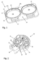
- FIG 1 is a perspective view of the top of a mounting plate 10 made of plastic, which for quick assembly of two connector elements is set up.
- the mounting plate 10 has one for this flat, approximately rectangular support body 11 with two circular Recesses 19a, 19b.
- the recesses 19a, 19b are each from one protruding upwards on the outside of the mounting plate 10 Collar 12 surrounded, which in view of the relatively thin mounting plate 10 for a sufficient height for receiving the counter thread and for provides a distance from the plane of the support body 11.
- a (counter) thread with a only interrupted and partially offset thread trained which can be formed by a simple two-jaw tool.
- This single thread consists of a first section 18, which is extends over a small angular range of typically 10 ° to 30 °. in the The thread is connected to the first section 18 by an interruption or a missing piece 17a interrupted.
- the missing piece 17a extends also over a relatively small angular range of typically 10 ° to 30 °.
- Following the interruption 17a follows second, longer section 16 of the thread, which extends over a range of typically extends 220 ° ⁇ 40 °.
- the collar 12 is on one long side of the Mounting plate 10 extended by a rectangular frame 13, which as Base for the hinged lid connection 23 ( Figure 2) of a plug element 20 serves.
- FIG. 2 shows the rear or underside of a plug device element 20 shown, which are connected to the mounting plate shown in Figure 1 can.
- the essentially cylindrical connector element 20 has one - Insert 21 with electrical connecting parts, which is not of interest here on which is sleeve-shaped from a flange with an external thread is surrounded.
- the thread basically corresponds to that of known plug-in device elements provided external thread (for example series StarTOP 16A / 3p from Mennekes Elektrotechnik, Kirchhundem), making it a Screw together with an associated cover housing in a known manner allowed.
- the thread is after a first section 26 by one Missing piece 25 is interrupted before continuing through another section 24 becomes.
- the further section 24 is in the area due to a second missing piece a hinged lid connection 23 interrupted and divided into two parts. This optional interruption has the primary purpose of installing a protective conductor to enable according to French standard.
- the angular range over which the first missing piece 25 extends at least corresponds to the angular extent of the first section 18 of the mating thread on the mounting plate 10 of FIG. 1.
- the threaded portion 24 is in the second round by another missing piece 25 'interrupted, which is the same length as the first Missing piece 25 is and axially aligned with it.
- FIG. 2 on the underside of the hinged cover connection 23, which is used to attach a hinged lid (not shown) recognizable spring hook 22.
- the spring hook 22 snaps when the connection position is reached (Installation position) inside the base 13 of the hinged cover connection.
- the base 13 is the Hinged lid connection and / or the hinged lid connection 23 with a Provide side slit through which a screwdriver blade can be used if necessary Unlocking the spring hook 22 can be inserted.
- FIG. 3 shows a mounting plate 10 with a plug device socket already inserted 20 'in the installed position and a second connector socket 20, which is already inserted in the corresponding recess, but not yet in the end position is screwed.
- the second can 20 is fixed by rotating in the direction of the Arrow, whereby an angle of (360 ° - ⁇ ) is covered.
- the one Full rotation missing angle ⁇ is approximately 120 °. While screwing in a stroke of typically 2.5 mm is covered, which is approx. 45 ° before the end of the Rotation leads to an increasing torque, since one by about 0.5 mm raised ring seal in the mounting plate 10 (not shown) depressed must become. Due to the projecting hinged lid connection 23 is during Screwing movement of the box 20 given a good force application point.
- Figure 4 shows an exploded view of the connector system of Figure 3 after reaching the installation position through the box 20.
- the mounting thread on the can 20 and the mating thread on the mounting plate 10 in the Installation position a maximum coverage.
- the introduction of force is hereby evenly distributed over the entire circumference, which is important for a constant and even pressure on the captive arranged on the collar 12 Sealing ring (not shown) of the mounting plate 10.
- the mounting thread 120 has a thread line, which by a Interruption or a missing piece 125 in a short first Section 126 and a second section 124 is divided.
- the second Section 124 is also interrupted by another missing piece 125 ', which is the same length as the first missing piece 125 and is axially aligned with it.
- the counter thread 110 is about the first two thread revolutions in Essentially complementary to the mounting thread 120. With others Words are where the mounting thread 120 has missing pieces 125, 125 ', Formed sections 118, 118 'of the counter thread 110, and where Sections 126, 124 of the mounting thread 120 are formed, missing pieces 117, 117 'of the counter thread 110. From the third thread revolution, that is Mounting thread 120 and the counter thread 110 continuously formed.
- the mounting thread 120 could also be more than two axially aligned missing pieces 125, 125 'or the mating thread 110 more than two axially have aligned sections 116, 116 '.
- everyone could Thread revolutions must be provided with interruptions. The representation of Figure 5 is therefore only to be understood as an example.
- the two threads 110, 120 are joined together so that the first section 126 of the mounting thread 120 by the interruption 117 and possibly beyond also by the interruption 117 'in the first and second ones below Thread of the counter thread 110 arrives. Then the two Threads 110, 120 are screwed together. Even if it is up to Rotation angle covered by the end position is less than 360 ° "Leading" first section 126 reaches the maximum non-overlap Thread sections are smaller than that at a full rotation of 360 ° missing angles.
- the axial connection of the threads 110, 120 over several Thread revolutions has the advantage that accordingly many threads contribute to the hold. Furthermore, different thicknesses can be used Intermediate components between the connector element 20 and the mounting plate 10 can be accommodated.
Landscapes
- Connector Housings Or Holding Contact Members (AREA)
Applications Claiming Priority (3)
| Application Number | Priority Date | Filing Date | Title |
|---|---|---|---|
| DE10301879 | 2003-01-17 | ||
| DE2003101879 DE10301879B3 (de) | 2003-01-17 | 2003-01-17 | Steckvorrichtungselement mit Montagegewinde |
| EP03028863 | 2003-12-16 |
Related Parent Applications (1)
| Application Number | Title | Priority Date | Filing Date |
|---|---|---|---|
| EP03028863 Division | 2003-01-17 | 2003-12-16 |
Publications (2)
| Publication Number | Publication Date |
|---|---|
| EP1473806A2 true EP1473806A2 (fr) | 2004-11-03 |
| EP1473806A3 EP1473806A3 (fr) | 2005-06-29 |
Family
ID=32991916
Family Applications (1)
| Application Number | Title | Priority Date | Filing Date |
|---|---|---|---|
| EP04102329A Withdrawn EP1473806A3 (fr) | 2003-01-17 | 2003-12-16 | Elément de connexion avec un taraudage de montage |
Country Status (1)
| Country | Link |
|---|---|
| EP (1) | EP1473806A3 (fr) |
Cited By (2)
| Publication number | Priority date | Publication date | Assignee | Title |
|---|---|---|---|---|
| EP1923966A3 (fr) * | 2006-11-14 | 2010-10-20 | ERICH JAEGER GmbH + Co. KG | Prise |
| EP1688656B1 (fr) * | 2005-02-02 | 2012-12-19 | Truma Gerätetechnik GmbH & Co. KG | Système rapide de connexion pour connexion filetée |
Family Cites Families (3)
| Publication number | Priority date | Publication date | Assignee | Title |
|---|---|---|---|---|
| US5564937A (en) * | 1994-12-21 | 1996-10-15 | Illinois Tool Works Inc. | Light bulb socket assembly |
| DE10045263B4 (de) * | 2000-09-13 | 2004-05-06 | ITT Manufacturing Enterprises, Inc., Wilmington | Gerätesteckverbinder |
| AT5235U1 (de) * | 2001-04-12 | 2002-04-25 | Pc Electric Gmbh | Flanschteil |
-
2003
- 2003-12-16 EP EP04102329A patent/EP1473806A3/fr not_active Withdrawn
Cited By (2)
| Publication number | Priority date | Publication date | Assignee | Title |
|---|---|---|---|---|
| EP1688656B1 (fr) * | 2005-02-02 | 2012-12-19 | Truma Gerätetechnik GmbH & Co. KG | Système rapide de connexion pour connexion filetée |
| EP1923966A3 (fr) * | 2006-11-14 | 2010-10-20 | ERICH JAEGER GmbH + Co. KG | Prise |
Also Published As
| Publication number | Publication date |
|---|---|
| EP1473806A3 (fr) | 2005-06-29 |
Similar Documents
| Publication | Publication Date | Title |
|---|---|---|
| AT523016B1 (de) | Steckverbinder | |
| EP1891710A1 (fr) | Connecteur electrique, element male et element femelle | |
| EP3625860A1 (fr) | Passage de câble | |
| EP2240987B1 (fr) | Dispositif a enfichage | |
| EP3292603B1 (fr) | Entrée de ligne/câble | |
| EP2434586A1 (fr) | Connecteur à fiche électrique doté d'un écrou-raccord | |
| EP3586415A1 (fr) | Accouplement à fiche avec antitraction pour un câble de raccordement | |
| DE9110007U1 (de) | Kabeldurchführungsvorrichtung | |
| EP3688851B1 (fr) | Passe-câble à vis | |
| DE102008057473B4 (de) | Kabeldurchführung | |
| DE102004043518B3 (de) | Vorrichtung zum Anschluss eines Koaxialkabels an ein Gehäuse | |
| DE3517933C2 (de) | Schloßmechanismus mit einer Sperrklinkenwelle | |
| EP3290622A1 (fr) | Dispositif de compensation d'une différence de longueur entre une serrure à cylindre et un vantail | |
| WO2017182028A1 (fr) | Dispositif de fixation pour fixer une plaque formant bride à un boîtier d'armoire de distribution et boîtier d'armoire de distribution correspondant | |
| DE10301879B3 (de) | Steckvorrichtungselement mit Montagegewinde | |
| EP0272199B1 (fr) | Goulotte de câbles avec au moins un profilé de goulotte en aluminium et une pièce de raccordement pour un conducteur de protection | |
| EP1473806A2 (fr) | Elément de connexion avec un taraudage de montage | |
| DE10206063B4 (de) | Anbau-Steckvorrichtung | |
| EP2750269A1 (fr) | Groupe motopompe | |
| EP1318575B1 (fr) | Dispositif connecteur pour montage | |
| EP2802040B1 (fr) | Appareil électronique | |
| DE9302282U1 (de) | Elektrischer Rundsteckverbinder in wasserdichter und hochfrequenzdichter Ausführung | |
| DE102011076210B4 (de) | Befestigungsanordnung für zwei benachbarte Sanitärarmaturen | |
| DE4443545B4 (de) | Steckverbinder | |
| DE202019101084U1 (de) | Anschlusseinrichtung |
Legal Events
| Date | Code | Title | Description |
|---|---|---|---|
| PUAI | Public reference made under article 153(3) epc to a published international application that has entered the european phase |
Free format text: ORIGINAL CODE: 0009012 |
|
| AK | Designated contracting states |
Kind code of ref document: A2 Designated state(s): AT BE BG CH CY CZ DE DK EE ES FI FR GB GR HU IE IT LI LU MC NL PT RO SE SI SK TR |
|
| AX | Request for extension of the european patent |
Extension state: AL LT LV MK |
|
| PUAL | Search report despatched |
Free format text: ORIGINAL CODE: 0009013 |
|
| AK | Designated contracting states |
Kind code of ref document: A3 Designated state(s): AT BE BG CH CY CZ DE DK EE ES FI FR GB GR HU IE IT LI LU MC NL PT RO SE SI SK TR |
|
| AX | Request for extension of the european patent |
Extension state: AL LT LV MK |
|
| 17P | Request for examination filed |
Effective date: 20050701 |
|
| AKX | Designation fees paid | ||
| STAA | Information on the status of an ep patent application or granted ep patent |
Free format text: STATUS: THE APPLICATION IS DEEMED TO BE WITHDRAWN |
|
| 18D | Application deemed to be withdrawn |
Effective date: 20051230 |
|
| REG | Reference to a national code |
Ref country code: DE Ref legal event code: 8566 |