EP1473970A2 - Einsatzmodul für Miniatur-Hörhilfegerät - Google Patents
Einsatzmodul für Miniatur-Hörhilfegerät Download PDFInfo
- Publication number
- EP1473970A2 EP1473970A2 EP04076278A EP04076278A EP1473970A2 EP 1473970 A2 EP1473970 A2 EP 1473970A2 EP 04076278 A EP04076278 A EP 04076278A EP 04076278 A EP04076278 A EP 04076278A EP 1473970 A2 EP1473970 A2 EP 1473970A2
- Authority
- EP
- European Patent Office
- Prior art keywords
- frame
- hearing aid
- insert module
- module according
- faceplate
- Prior art date
- Legal status (The legal status is an assumption and is not a legal conclusion. Google has not performed a legal analysis and makes no representation as to the accuracy of the status listed.)
- Granted
Links
Images




Classifications
-
- H—ELECTRICITY
- H04—ELECTRIC COMMUNICATION TECHNIQUE
- H04R—LOUDSPEAKERS, MICROPHONES, GRAMOPHONE PICK-UPS OR LIKE ACOUSTIC ELECTROMECHANICAL TRANSDUCERS; ELECTRIC HEARING AIDS; PUBLIC ADDRESS SYSTEMS
- H04R25/00—Electric hearing aids
- H04R25/65—Housing parts, e.g. shells, tips or moulds, or their manufacture
-
- H—ELECTRICITY
- H04—ELECTRIC COMMUNICATION TECHNIQUE
- H04R—LOUDSPEAKERS, MICROPHONES, GRAMOPHONE PICK-UPS OR LIKE ACOUSTIC ELECTROMECHANICAL TRANSDUCERS; ELECTRIC HEARING AIDS; PUBLIC ADDRESS SYSTEMS
- H04R25/00—Electric hearing aids
- H04R25/60—Mounting or interconnection of hearing aid parts, e.g. inside tips, housings or to ossicles
-
- H—ELECTRICITY
- H04—ELECTRIC COMMUNICATION TECHNIQUE
- H04R—LOUDSPEAKERS, MICROPHONES, GRAMOPHONE PICK-UPS OR LIKE ACOUSTIC ELECTROMECHANICAL TRANSDUCERS; ELECTRIC HEARING AIDS; PUBLIC ADDRESS SYSTEMS
- H04R25/00—Electric hearing aids
- H04R25/60—Mounting or interconnection of hearing aid parts, e.g. inside tips, housings or to ossicles
- H04R25/602—Mounting or interconnection of hearing aid parts, e.g. inside tips, housings or to ossicles of batteries
-
- B—PERFORMING OPERATIONS; TRANSPORTING
- B33—ADDITIVE MANUFACTURING TECHNOLOGY
- B33Y—ADDITIVE MANUFACTURING, i.e. MANUFACTURING OF THREE-DIMENSIONAL [3D] OBJECTS BY ADDITIVE DEPOSITION, ADDITIVE AGGLOMERATION OR ADDITIVE LAYERING, e.g. BY 3D PRINTING, STEREOLITHOGRAPHY OR SELECTIVE LASER SINTERING
- B33Y80/00—Products made by additive manufacturing
-
- H—ELECTRICITY
- H04—ELECTRIC COMMUNICATION TECHNIQUE
- H04R—LOUDSPEAKERS, MICROPHONES, GRAMOPHONE PICK-UPS OR LIKE ACOUSTIC ELECTROMECHANICAL TRANSDUCERS; ELECTRIC HEARING AIDS; PUBLIC ADDRESS SYSTEMS
- H04R2225/00—Details of deaf aids covered by H04R25/00, not provided for in any of its subgroups
- H04R2225/023—Completely in the canal [CIC] hearing aids
-
- H—ELECTRICITY
- H04—ELECTRIC COMMUNICATION TECHNIQUE
- H04R—LOUDSPEAKERS, MICROPHONES, GRAMOPHONE PICK-UPS OR LIKE ACOUSTIC ELECTROMECHANICAL TRANSDUCERS; ELECTRIC HEARING AIDS; PUBLIC ADDRESS SYSTEMS
- H04R2225/00—Details of deaf aids covered by H04R25/00, not provided for in any of its subgroups
- H04R2225/025—In the ear hearing aids [ITE] hearing aids
-
- H—ELECTRICITY
- H04—ELECTRIC COMMUNICATION TECHNIQUE
- H04R—LOUDSPEAKERS, MICROPHONES, GRAMOPHONE PICK-UPS OR LIKE ACOUSTIC ELECTROMECHANICAL TRANSDUCERS; ELECTRIC HEARING AIDS; PUBLIC ADDRESS SYSTEMS
- H04R25/00—Electric hearing aids
- H04R25/55—Electric hearing aids using an external connection, either wireless or wired
- H04R25/556—External connectors, e.g. plugs or modules
-
- H—ELECTRICITY
- H04—ELECTRIC COMMUNICATION TECHNIQUE
- H04R—LOUDSPEAKERS, MICROPHONES, GRAMOPHONE PICK-UPS OR LIKE ACOUSTIC ELECTROMECHANICAL TRANSDUCERS; ELECTRIC HEARING AIDS; PUBLIC ADDRESS SYSTEMS
- H04R25/00—Electric hearing aids
- H04R25/60—Mounting or interconnection of hearing aid parts, e.g. inside tips, housings or to ossicles
- H04R25/609—Mounting or interconnection of hearing aid parts, e.g. inside tips, housings or to ossicles of circuitry
-
- H—ELECTRICITY
- H04—ELECTRIC COMMUNICATION TECHNIQUE
- H04R—LOUDSPEAKERS, MICROPHONES, GRAMOPHONE PICK-UPS OR LIKE ACOUSTIC ELECTROMECHANICAL TRANSDUCERS; ELECTRIC HEARING AIDS; PUBLIC ADDRESS SYSTEMS
- H04R25/00—Electric hearing aids
- H04R25/65—Housing parts, e.g. shells, tips or moulds, or their manufacture
- H04R25/658—Manufacture of housing parts
Definitions
- the present invention relates to miniature hearing aid insert module comprising a socket module and a substantially closed-loop frame comprising electrically conductive portions.
- the present invention relates to a hearing aid insert module having a closed-loop frame having engaging means adapted to releasably coupling the hearing aid insert module to e.g. a faceplate or a hearing aid housing.
- Miniature hearing aid insert modules are known.
- the hearing aid includes a thin-walled, hard or flexible plastics material faceplate which is design to co-operate with the natural shell-like form of a human pinna. Moreover, the faceplate partially houses an electronic hearing aid amplification module which is also accommodated within an integral projection from the faceplate which is arranged to engage in use into an auditory canal associated with the pinna.
- a hearing aid comprising a faceplate, a battery holder for accommodating a battery and a signal path incorporated within a shell part.
- the path includes a microphone coupled to a signal processor coupled in turn to an output acoustic transducer.
- the battery is connected via its battery holder to the signal processor for providing energization thereto when the aid is operational.
- the microphone and the battery holder with its associated battery are spatially disposed at the faceplate, whereas the signal processor and the output transducer are disposed in the shell part, the shell part being suitable for insertion into a human auditory canal in use.
- An insert module associated with the faceplate is used to house electrical connections from the aforesaid battery to the signal processor.
- the insert module serves also to mechanically support the microphone.
- US 6,430,296 discloses a modular hearing aid comprising a hollow plug having a generally irregular conical shape and an exterior opening which is covered by a faceplate, in which a recess is formed for removable arrangement of a battery as well as an electronic module.
- the recess comprises a first region for insertion of the battery and a second region coherent with the first region for placing of a socket part of the electronic module.
- the faceplate is formed with engaging means for the socket part, whereas further parts of the electronic module are placed below the faceplate.
- the recess is formed such that at removal of the battery the first and second regions together allow passage also of further parts for removal of the complete electronic module from the modular hearing aid.
- a disadvantage of the modular hearing aid disclosed in US 6,430,296 is that resilient lugs 19 only contact the edge of the faceplate recess along a minor portion of the edge and leaves coupling between the hearing aid insert module and hearing aid faceplate fragile.
- SLA-shells suffer from one significant drawback - namely that these shells are more fragile than traditional injection moulded shell parts of thermo-plastic material. Therefore, utilizing a substantially closed-loop frame in accordance with the present invention is a significant advantage since the closed-loop frame allows a large contact area between the insert module and hearing aid faceplate to facilitate a robust coupling.
- a hearing aid insert module comprising:
- the invention is of advantage in that releasably coupling the surface portion of the hearing aid to the socket module via the frame renders the insert module easier to manufacture, to user-customize and to repair.
- a "substantially closed-loop" frame is to be construed to include a rectangular-shaped frame structure having a gap or opening in the frame structure as long as the frame structure possesses a mechanical stiffness neutralising the effect of said gap or opening.
- the engaging means may be adapted to releasably coupling the hearing aid insert module to a faceplate of a hearing aid.
- the frame is arranged to impart a majority of structural rigidity to the surface portion or faceplate when inserted therein.
- Such rigidity is of benefit in that the surface portion or faceplate is capable in use of applying a flexural component to the frame which could damage the frame if not of sufficiently substantial rigidity.
- the frame is arranged to accommodate power supplying means therein.
- the power supplying means typically comprises a user-replaceable battery; however, other types of power supplying means are additionally or alternatively feasible, for example a photocell to convert optical radiation incident upon the insert module to electrical power to operate electronic processing means connected to the socket module.
- the insert module additionally comprises a battery lid coupled to the socket module for holding the user-replaceable battery.
- a battery lid renders the power supplying means more concealed when in use in the insert module.
- the lid is pivotally mounted to the socket module.
- Such pivotal retention of the lid to the socket module is of advantage in that the lid is of relatively small size relative to size of fingers of the user, whereby retention of the lid onto the insert module renders the lid less likely to be dropped, lost or mislaid.
- Ease of use is of especial importance when the insert module is used by elderly people who suffer one or more of poor eyesight, reduced finger actuation as a consequence of arthritis, and lack of precision of finger movement due to motor neurone disorders such as Parkinson's disease.
- the battery lid and the frame comprise locking means for snap-fit retaining the battery lid in a locked engagement with the frame.
- Such snap-fit retention is convenient in use and is capable of preventing unintentional exposure of the supplying means, thereby rendering the insert module potentially more concealed in use.
- the frame is arranged to hinder disengagement of the surface portion or faceplate therefrom when the supplying means is installed within the insert module.
- Such hindrance of surface portion or faceplate disengagement from the frame is of benefit in that it is capable of rendering the hearing aid insert module more robust in use.
- the frame is arranged to function as an electrical connection from the supplying means to processing means connected to the socket module.
- Such synergistic multifunction of the frame is of advantage in rendering the insert module more compact, easier and less expensive to manufacture and potentially more reliable.
- the frame comprises a first electrically conductive portion adapted to contact a first power supply terminal of a battery, and a second electrically conductive portion adapted to contact a second power supply terminal of the battery - the first and second electrically conducting portions electrically isolated.
- the first and second electrically conductive portions are electrically isolated by an isolating member forming an integral part of the insert module.
- the frame is of pressed-formed sheet metal construction.
- Press-forming of metal is an inexpensive and rapid method of manufacturing the frame.
- using a metal construction allows the frame to be manufactured in very small dimensions and still maintain a satisfactory strength.
- the frame comprises one or more outwardly-directed projections for engaging onto upper and lower peripheral surfaces of the surface portion of faceplate.
- projection engagement onto outermost upper and lower peripheral surfaces of the surface portion or faceplate is especially beneficial in rendering mechanical coupling between the surface portion or faceplate and the frame robust; such an arrangement should be juxtaposed with an arrangement where the one or more projections engage into a region within the surface portion or faceplate where more projection-plate contact area would superficially be anticipated to enhance robustness.
- said one or more projections are an integral part of the frame. Such construction potentially simplifies insert module manufacture and renders the insert module more robust.
- the frame is arranged so that application of releasing forces substantially along one axis is capable of releasing said one or more projections simultaneously from the surface portion or faceplate to enable assembly and/or disassembly of the surface portion or faceplate from the frame.
- the frame is fabricated from at least one shaped wire section.
- Such wire section construction is of benefit in that it is capable of rendering the insert module more compact and light weight.
- the frame is thereby susceptible to being fabricated by forming standard stock wire and thus simplifying manufacture of the insert module. More preferably, said at least one shaped wire section is at least partially moulded into the socket module.
- the hearing aid insert module may comprise a programming connector for conveying programming data between the insert module and an external hearing aid fitting system.
- the hearing aid insert module may further comprise microphone and/or a user-actuatable push-button.
- a hearing aid comprising a hearing aid insert module which comprises
- the hearing aid may comprise a signal processor means and a loudspeaker operatively coupled to the signal processor means.
- the hearing aid is of advantage in that its frame is capable of synergistically performing a plurality of functions. It will be appreciated that features of the invention can be combined in any combination without departing from the scope of the invention.
- FIG. 1 there are shown principal components of a hearing aid insert module according to the invention implemented as part of a hearing aid, the hearing aid being indicated generally by aid 10.
- the aid 10 comprises a faceplate 20 shaped to match spatial contours of that region of a human pinna to which the aid 10 is designed to interface.
- the plate 20 is fabricated from a relatively-thin plastics material sheet which is illustrated as substantially planar but which is susceptible to being fashioned to the profile of the aforesaid human pinna; for example, the plate 20 is susceptible to thermal contouring onto a mould cast impression of the pinna.
- the plate 20 is susceptible to being fabricated by one or more of stereo lithography and directed plastics material jet moulding.
- the sheet is in a range of 0.1 mm to 1 mm thick, and more preferably in a range of 0.2 to 0.6 mm thick.
- the sheet preferably comprises one or more layers of material therein for optimizing its physical robustness and appearance.
- the aid 10 additionally comprises a peripheral frame 30 to which is pivotally mounted a lid 40, and a socket module 50 suitable for insertion into a human's auditory canal.
- a recess 60 for receiving a battery 70 for providing electrical power to the aid 10 when in operation.
- the recess 60 includes compliant electrical contacts for engaging onto electrical terminals of the battery 70.
- the frame 30 preferably synergistically serves several functions, for example it is capable of serving at least in part as the electrical contacts for the battery 70; such an arrangement not only results in fewer piece parts being required to fabricate the aid 10, but also assists to reduce its physical size as well as rendering it more robust in use.
- the socket module 50 is adapted to receive an electronic module (not shown) comprising a microphone for receiving sound at the aid 10.
- an electrical output from the microphone is connected to a signal processor and, in turn from the processor, to an acoustic output transducer remote from the plate 20 and the microphone; the microphone, the processor and the output transducer are not shown in Figure 1.
- the processor is merely operable to provide an amplification function from the microphone to the output transducer.
- the processor is capable of performing one or more additional functions such as a frequency filtration function, an audio dynamic range compression function, a signal phase adjustment function and a signal frequency shifting (heterodyne) function; other functions are additionally feasible.
- the processing function is implemented digitally and susceptible to modification by way of digital reprogramming.
- a user of the aid 10 installs the battery 70 therein by pivotally lifting the lid 40 and then inserting the battery 70 into the recess 60 so that electrodes of the battery 70 engage onto the aforesaid electrical contacts of the recess 60.
- the battery 70 provides electrical power to the processor so that it performs one or more signal processing functions on electrical signals generated from the microphone to provide a corresponding processed output signal for driving the output transducer.
- the aid 10 is designed so that the hearing aid module according to the present invention is a standardized component detachable from the plate 20; such construction enables the plate 20 to be customized for each user and then affixed to the hearing aid module for subsequent use by the user.
- the frame 30 is designed to be sufficiently rigid so that the user is able to manipulate the aid 10 by holding its plate 20 whilst pulling on the lid 40 to gain access to the recess 60 and its battery 70 for periodic replacement thereof.
- the frame 30 is preferably more relatively rigid than the plate 20.
- the frame 30 is sufficiently rigidly attachable to the plate 20 to remain affixed thereto in normal use.
- the lid 40 is designed to be a retained part of the frame 30.
- the lid 40 is snap-fittable to the frame 30 in a manner which will be elucidated in greater detail in the following description.
- the frame 30 is beneficially fabricated from a resiliently flexible material, for example a metallic material such as spring steel, phosphor-bronze, or another elastic substantially conductive metal or metal alloy.
- the frame 30 is susceptible to being fabricated from exotic high-strength materials such as carbon fibre composite and/or Kevlar composite materials.
- the frame 30 is implemented as a pressed-formed metal component; preferably, the frame 30 is fabricated by metal stamping and/or lithographic electro-etching processes from planar metal sheet followed by subsequent metal pressing operations to form the frame 30 into its shape as illustrated in Figure 2.
- the frame 30 includes two upwardly projecting hinges 110 for receiving the lid 40 as indicated by 100.
- Each hinge 110 comprises an associated hole 115 for receiving a raised dimple (not shown) moulded into a lateral surface of the lid 40, such that the lid 40 is capable of pivoting about an axis intersection a central region of each of the holes 115; preferably, the lid 40 is a plastics material moulded component, although it is also susceptible to being fabricated as a pressed-formed metal sheet component; alternatively, the lid 40 is capable of being fabricated as a hybrid pressed-metal and plastics material moulded component.
- the lid 40 itself includes a curved section 120 at its end whereat it pivots in use to render the hinges 110 substantially outwardly invisible to the user.
- the frame 30 includes four outwardly-projecting lateral tabs 130 on two most elongate edges of the frame 30 as illustrated, and four outwardly-projecting end tabs 140 on at least one less elongate end edge of the frame 30 as illustrated.
- the lateral tabs 130 are relatively broader than the end tabs 140, the tabs 130 being formed substantially midway along the most elongate edges of the frame 30.
- the lateral tabs 130 are arranged to interface and co-operate with upper and lower major surfaces of the faceplate 20 when engaged thereonto, such interfacing being more apparent in Figure 5.
- the end tabs 140 are formed near corner regions of the frame 30 as illustrated in Figure 2 and substantially away from a midpoint along the end edge.
- the end tabs 140 are arranged to interface and engage onto upper and lower major faces of the faceplate 20.
- Such upper and lower major face engagement of the frame 30 onto the faceplate 20 is found by the inventor to be highly advantageous to render the aid 10 physically robust and yet straightforward to assemble and/or disassemble.
- the dimple projection 160 is conveniently formed by a metal pressing operation.
- the frame 30 can be finished as a metallic component. Alternatively, at least in part, it is susceptible to having plastics material moulded therearound, especially in a region in the vicinity of the hinges 110.
- the aid 10 preferably includes a series of four electrical contacts indicated by 170 for providing electrical power connection from the battery 70 to the aforesaid signal processor of the aid 10.
- the contacts 170 are preferably implemented in a row as illustrated, and are compliant so as to resiliently engage onto corresponding electrical terminals of the battery 70 when inserted into the recess 60.
- a section of the frame 30 and a region of the faceplate 20 interfacing thereto are indicated generally by 200.
- the frame 30 is laterally compliant at its elongate edges so that inward-directed forces 210 applied thereto are susceptible to causing movement 220 at end edges of the frame 30 as illustrated.
- application of the forces 210 is susceptible to disengage not only the lateral tabs 130 but also the end tabs 140.
- Such an arrangement in Figure 3 is especially beneficial in that it enables the faceplate 20 to be readily and easily robustly engaged to the frame 30 and correspondingly readily intentionally disengaged therefrom; the arrangement is convenient when fabricating the aid 10 and also when replacing the insert module (including socket module and a electronic module connected thereto) or the faceplate 20 due to malfunction thereof or damage thereto respectively. It will be appreciated from Figure 3 that inclusion of the battery 70 within the recess 60 is capable of preventing the forces 210 causing movement of the tabs 130, 140 to disengage them from the faceplate 20; thus, the arrangement utilized in the aid 10 is not readily susceptible to disassembly when the aid 10 is in use.
- the lid 40 includes, preferably integrally therewith by way of plastics material moulding, a projection 320 with an associate indent 330 therein arranged to deformably engage onto the elongate dimple 160 when the lid 40 is closed against the frame 30.
- pivotal movement of the lid 40 and its projection 320 causes one or more of the end edge of the frame 30 and the projection 320 to resiliently deform in directions shown by an arrow 340 so that the lid 40 is snap-closeable to the frame 30.
- the elongate dimple 160 is susceptible to being included along at least one of the elongate sides of the frame 30, such inclusion being alternative or additional to inclusion of the dimple 160 in the end edge of the frame 30 remote from the hinges 110.
- other types of snap-closeable fixtures for the lid 40 to ensure reliable engagement with the frame 30 are possible.
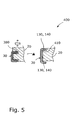
- FIG. 5 there is shown a cross-sectional view of the frame 30 engaging onto the faceplate 20.
- an arrangement preferred by the inventor is indicated by 400.
- the arrangement 400 involves including a recessed step 410 at a peripheral edge of an upper outwardly-directed surface of the faceplate 20 so that the tabs 130, 140 are substantially flush with the upper surface of the plate 20 when the frame 30 is engaged onto the plate 20, thereby providing enhanced aid 10 visual concealment when worn.
- the frame 30 is susceptible to being fabricated from pressed-formed metal sheet as described in the foregoing, it is also practicable to fabricate it from elastically resilient wire which is formed by bending to an appropriate shape for implementing the frame 30.
- Figure 6 there is shown an illustration of an alternative implementation of the aid 10 indicated generally by 500 wherein its frame 30 is implemented from resilient wire, for example phosphor bronze wire and/or spring steel wire.
- the use of wire to form the frame 30 is especially attractive as the frame 30 can be formed from a standard commodity wire and customized for purpose by a single wire-bending process.
- wire is drawn and tempered during its manufacture which imparts to it especially desirable resilient elastic properties appropriate for implementing the frame 30.
- the frame 30 is implemented using first and section wire sections 510, 520 respectively; the sections 510, 520 are folded back on themselves to provide a greater degree of engagement onto the faceplate 20.
- the wire sections 510, 520 are moulded into in an electrically-insulating plastics material block forming a part of the socket module 50 and project therefrom to terminate into an electrically-insulating cylindrical component 525 forming a hinge for the lid 40.
- the wire sections 510, 520 are arranged to engage onto lateral projections from the faceplate 20, for example the wire section 520 is arranged to engage onto a lateral projection 530 for mechanically retaining the frame 30 onto the faceplate 20 in use.
- the sections 510, 520 are arranged to be resiliently deflectable by inwardly-directed forces 540 applied for disengaging the sections 510, 520 from the projections 530 in the plate 20 to release the frame 30 from the plate 20. Such release is preferably not practicable when the battery 70 is included within the frame 30 as inclusion hinders inwardly-directed deflection of the sections 510, 520.
- a recess 550 in the faceplate 20 as illustrated.
- the wire sections 510, 520 are fabricated to overhang at their folded-back ends 560, 570 respectively the recess 550 each by a distance 580, such overhang imparting the ends 560, 570 with elastic flexibility in a direction 590 for resiliently contacting onto positive and negative terminals of the battery 70 when installed within the frame 30 formed by the two sections 510, 520.
- the wire sections 510, 520 are thereby capable of performing several functions synergistically, namely providing mechanical strength to the socket module 50, providing attachment to the faceplate 20 and also providing electrical connections for the battery 70; such synergy is susceptible to rendering the aid 500 potentially at least one of more robust, more compact and less expensive to manufacture.
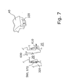
- the component 525 is preferably capable of rotating about its elongate axis relative to the sections 510, 520. More preferably, the lid 40 at its end remote from the component 525 is provided with the projection 320 arranged so as to be also susceptible to engagement in a snap-fit manner onto the ends 560, 570 of the sections 510, 520, thereby also enabling these sections 510, 520 to serve as a closure-locking arrangement for the lid 40.
- FIG. 7 Such a locking arrangement is illustrated in Figure 7 wherein an upwardly directed force 600 applied to the lid 40 to pivot it relative to the frame 30 when accessing the battery 70 causes the ends 560, 570 to be resiliently directed outwardly, as indicated by an arrow 610, to allow the lid 40 to be released from its snap-closed position.
- the frame 30 implemented from shaped wire sections can be fabricated in other arrangements to assist with manufacture of a hearing aid according to the invention.
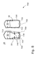
- Figure 8 there is shown an embodiment of a hearing aid according to the invention indicated generally by 700 where the frame 30 is implemented as a loop of wire 710 rigidly attached at its free ends to the socket module 50 as illustrated.
- the loop 710 is arranged to engage onto projections 720 from the faceplate 20 for retaining the socket module 50 in mechanical connection therewith.
- the loop 710 is so arranged that lateral inwardly-directed forces denoted by arrows 740 are capable of causing orthogonal corners of the loop 710 normally abutting onto the projections 720 to move inwardly as denoted by arrows 750, thereby enabling the frame 30 fabricated as the loop 710 to be disengaged from the faceplate 20; such disengagement is hindered when the battery 70 is included within the frame 30 implemented so.
- the loop 710 includes at a central end region thereof a bent projection 730 suitable for engaging onto the aforementioned projection 320 of the lid 40 for providing snap-fit retention of the lid 40 onto the frame 30.
- FIG 9 there is shown part of a hearing aid according to the invention indicated generally by 800.
- the aid 800 incorporates its frame 30 fabricated using a folded section of wire 805 whose free ends 810 are terminated in a cylindrical component 820 as illustrated.
- the component 820 is capable of functioning as a snap-locking closure for the lid 40 (not shown in Figure 9) of the aid 800.
- the wire section 805 is beneficially moulded into the socket module 50 fabricated from moulded plastics material and continued therethrough to form a loop 825 remote from the component 820 and its ends 810.
- the lid 40 is provided with a snap-fit projection 830 at its pivotal end so that, for example manufacture, it is snap-fittable to the loop 825 as indicated by an arrow 835.
- the socket module 50 is provided with a central raised portion 910 into which the wire section 805 terminates as illustrated, the wire section 805 being so formed that two access regions 920 are provided laterally to the raised portion 910 so that one or more snap-fit projections 830 at the pivotal end of the lid 40 are able to snap-engage onto the access regions 920.
Landscapes
- Engineering & Computer Science (AREA)
- Acoustics & Sound (AREA)
- Neurosurgery (AREA)
- Otolaryngology (AREA)
- Physics & Mathematics (AREA)
- General Health & Medical Sciences (AREA)
- Health & Medical Sciences (AREA)
- Signal Processing (AREA)
- Manufacturing & Machinery (AREA)
- Casings For Electric Apparatus (AREA)
- Adornments (AREA)
- Packages (AREA)
- Audible-Bandwidth Dynamoelectric Transducers Other Than Pickups (AREA)
- Coupling Device And Connection With Printed Circuit (AREA)
Applications Claiming Priority (2)
| Application Number | Priority Date | Filing Date | Title |
|---|---|---|---|
| US46672403P | 2003-05-01 | 2003-05-01 | |
| US466724 | 2003-05-01 |
Publications (3)
| Publication Number | Publication Date |
|---|---|
| EP1473970A2 true EP1473970A2 (de) | 2004-11-03 |
| EP1473970A3 EP1473970A3 (de) | 2006-05-17 |
| EP1473970B1 EP1473970B1 (de) | 2008-07-16 |
Family
ID=32990987
Family Applications (1)
| Application Number | Title | Priority Date | Filing Date |
|---|---|---|---|
| EP04076278A Expired - Lifetime EP1473970B1 (de) | 2003-05-01 | 2004-04-30 | Einsatzmodul für Miniatur-Hörhilfegerät |
Country Status (5)
| Country | Link |
|---|---|
| US (1) | US7403630B2 (de) |
| EP (1) | EP1473970B1 (de) |
| AT (1) | ATE401759T1 (de) |
| DE (1) | DE602004015017D1 (de) |
| DK (1) | DK1473970T3 (de) |
Cited By (2)
| Publication number | Priority date | Publication date | Assignee | Title |
|---|---|---|---|---|
| WO2009074360A1 (de) | 2007-12-12 | 2009-06-18 | Siemens Medical Instruments Pte. Ltd. | Hörvorrichtung mit batterieklappenmodul |
| NL2020373B1 (nl) * | 2018-02-02 | 2019-08-12 | Exsilent Res Bv | Houder voor een elektronische inrichting |
Families Citing this family (70)
| Publication number | Priority date | Publication date | Assignee | Title |
|---|---|---|---|---|
| EP1715722A2 (de) * | 2005-04-21 | 2006-10-25 | Sonion Roskilde A/S | Ein Montagerahmen für angepasste Hörhilfegeräte |
| EP1838134B1 (de) * | 2006-03-23 | 2014-06-11 | Oticon A/S | Im-Ohr-Audiogerät sowie Verfahren zur Befestigung eines elektronischen Moduls in einem Hohlraum eines nach Kundenwunsch gefertigten Gehäuses für ein Im-Ohr-Audiogerät |
| JP5205371B2 (ja) * | 2006-06-23 | 2013-06-05 | ジーエヌ リザウンド エー/エス | 細長部材を有する補聴器 |
| US8374367B2 (en) * | 2006-06-23 | 2013-02-12 | Gn Resound A/S | Hearing aid with a flexible elongated member |
| US9357287B2 (en) | 2011-07-07 | 2016-05-31 | Sonion Nederland B.V. | Multiple receiver assembly and a method for assembly thereof |
| DK2723102T3 (da) | 2012-10-18 | 2019-01-02 | Sonion Nederland Bv | Transducer, høreapparat med transducer og en fremgangsmåde til betjening af transduceren |
| DK2723098T3 (en) | 2012-10-18 | 2017-03-13 | Sonion Nederland Bv | Double transducer with common membrane |
| US9807525B2 (en) | 2012-12-21 | 2017-10-31 | Sonion Nederland B.V. | RIC assembly with thuras tube |
| EP2750413B1 (de) | 2012-12-28 | 2017-02-22 | Sonion Nederland B.V. | Hörgerät |
| US9401575B2 (en) | 2013-05-29 | 2016-07-26 | Sonion Nederland Bv | Method of assembling a transducer assembly |
| EP2849463B1 (de) | 2013-09-16 | 2018-04-04 | Sonion Nederland B.V. | Wandler mit Feuchtigkeitstransportelement |
| DK3550852T3 (en) | 2014-02-14 | 2021-02-01 | Sonion Nederland Bv | A joiner for a receiver assembly |
| EP2908559B1 (de) | 2014-02-18 | 2016-10-05 | Sonion A/S | Verfahren zur Herstellung von Anordnungen für Hörgeräte |
| DK2914018T3 (en) | 2014-02-26 | 2017-01-30 | Sonion Nederland Bv | Speaker, luminaire and method |
| US9432774B2 (en) | 2014-04-02 | 2016-08-30 | Sonion Nederland B.V. | Transducer with a bent armature |
| EP2953380A1 (de) | 2014-06-04 | 2015-12-09 | Sonion Nederland B.V. | Akustische Übersprechkompensation |
| US9729974B2 (en) | 2014-12-30 | 2017-08-08 | Sonion Nederland B.V. | Hybrid receiver module |
| EP3051841B1 (de) | 2015-01-30 | 2020-10-07 | Sonion Nederland B.V. | Hörer mit aufgehängter motoranordnung |
| EP3057339B1 (de) | 2015-02-10 | 2020-09-23 | Sonion Nederland B.V. | Mikrofonmodul mit gemeinsamer mittlerer toneinlassanordnung |
| DK3073764T3 (en) | 2015-03-25 | 2021-05-10 | Sonion Nederland Bv | A hearing aid comprising an insert member |
| US9980029B2 (en) | 2015-03-25 | 2018-05-22 | Sonion Nederland B.V. | Receiver-in-canal assembly comprising a diaphragm and a cable connection |
| DK3133829T3 (da) | 2015-08-19 | 2020-06-22 | Sonion Nederland Bv | Lydgiverenhed med forbedret frekvensrespons |
| US10433077B2 (en) | 2015-09-02 | 2019-10-01 | Sonion Nederland B.V. | Augmented hearing device |
| US9668065B2 (en) | 2015-09-18 | 2017-05-30 | Sonion Nederland B.V. | Acoustical module with acoustical filter |
| US10021494B2 (en) | 2015-10-14 | 2018-07-10 | Sonion Nederland B.V. | Hearing device with vibration sensitive transducer |
| DK3160157T3 (en) | 2015-10-21 | 2018-12-17 | Sonion Nederland Bv | Vibration-compensated vibroacoustic device |
| US10582303B2 (en) | 2015-12-04 | 2020-03-03 | Sonion Nederland B.V. | Balanced armature receiver with bi-stable balanced armature |
| EP3185584B1 (de) | 2015-12-21 | 2020-04-22 | Sonion Nederland B.V. | Receiver-anordnung mit ausgeprägter längsrichtung |
| US9866959B2 (en) | 2016-01-25 | 2018-01-09 | Sonion Nederland B.V. | Self-biasing output booster amplifier and use thereof |
| EP3200479A3 (de) | 2016-01-28 | 2017-08-30 | Sonion Nederland B.V. | Elektrostatischer schallgenerator und anordnung mit elektrostatischem schallgenerator und transformator |
| DK3232685T3 (en) | 2016-04-13 | 2021-04-19 | Sonion Nederland Bv | A dome for a personal audio device |
| US10078097B2 (en) | 2016-06-01 | 2018-09-18 | Sonion Nederland B.V. | Vibration or acceleration sensor applying squeeze film damping |
| DK3703389T1 (en) | 2016-08-26 | 2020-11-09 | Sonion Nederland Bv | Vibration sensor with low-frequency roll-off response curve |
| EP3293985B1 (de) | 2016-09-12 | 2021-03-24 | Sonion Nederland B.V. | Hörer mit integrierter membranbewegungserkennung |
| EP3313097B1 (de) | 2016-10-19 | 2020-08-26 | Sonion Nederland B.V. | Ohrstöpsel oder -kuppel |
| EP3324649A1 (de) | 2016-11-18 | 2018-05-23 | Sonion Nederland B.V. | Wandler mit hoher empfindlichkeit |
| EP3324538A1 (de) | 2016-11-18 | 2018-05-23 | Sonion Nederland B.V. | Messschaltung mit einer verstärkerschaltung |
| US10327072B2 (en) | 2016-11-18 | 2019-06-18 | Sonion Nederland B.V. | Phase correcting system and a phase correctable transducer system |
| US20180145643A1 (en) | 2016-11-18 | 2018-05-24 | Sonion Nederland B.V. | Circuit for providing a high and a low impedance and a system comprising the circuit |
| DK3337184T3 (en) | 2016-12-14 | 2020-06-02 | Sonion Nederland Bv | An armature and a transducer comprising the armature |
| EP3337191B1 (de) | 2016-12-16 | 2021-05-19 | Sonion Nederland B.V. | Schallerzeugeranordnung |
| DK3337192T3 (en) | 2016-12-16 | 2021-05-10 | Sonion Nederland Bv | A receiver assembly |
| EP3343950A1 (de) | 2016-12-28 | 2018-07-04 | Sonion Nederland B.V. | Magnetanordnung |
| DK3343956T3 (en) | 2016-12-30 | 2021-05-03 | Sonion Nederland Bv | A circuit and a receiver comprising the circuit |
| DK3702322T3 (da) | 2016-12-30 | 2026-03-16 | Sonion Nederland Bv | Mikroelektromekanisk transducer |
| EP3586524B1 (de) * | 2017-02-23 | 2023-06-07 | Sonova AG | Ein hörgeätemodul, ein löse-werkzeug, ein hörgerät und eine methode zum entfernen eines moduls von einem gehäuse |
| DK3407625T3 (en) | 2017-05-26 | 2021-07-12 | Sonion Nederland Bv | Receiver with venting opening |
| DK3407626T3 (en) | 2017-05-26 | 2020-07-27 | Sonion Nederland Bv | A receiver assembly comprising an armature and a diaphragm |
| DK3429231T3 (da) | 2017-07-13 | 2023-04-11 | Sonion Nederland Bv | Høreanordning indbefattende vibrationsforebyggende indretning |
| US10820104B2 (en) | 2017-08-31 | 2020-10-27 | Sonion Nederland B.V. | Diaphragm, a sound generator, a hearing device and a method |
| EP3451688B1 (de) | 2017-09-04 | 2021-05-26 | Sonion Nederland B.V. | Schallerzeuger, abschirmung und öffnung |
| GB201714956D0 (en) | 2017-09-18 | 2017-11-01 | Sonova Ag | Hearing device with adjustable venting |
| DK3471437T3 (en) | 2017-10-16 | 2021-02-15 | Sonion Nederland Bv | A valve, a transducer comprising a valve, a hearing device and a method |
| EP4203497A3 (de) | 2017-10-16 | 2023-11-15 | Sonion Nederland B.V. | Persönliches hörgerät |
| EP3471432B1 (de) | 2017-10-16 | 2022-09-14 | Sonion Nederland B.V. | Klangkanalelement mit einem ventil und ein wandler mit dem klangkanalelement |
| EP3567873B1 (de) | 2018-02-06 | 2021-08-18 | Sonion Nederland B.V. | Verfahren zur steuerung eines akustischen ventils eines hörgerätes |
| DK3531713T3 (en) | 2018-02-26 | 2023-02-06 | Sonion Nederland Bv | Miniature Speaker with Acoustical Mass |
| EP3531720B1 (de) | 2018-02-26 | 2021-09-15 | Sonion Nederland B.V. | Anordnung aus einem empfänger und einem mikrofon |
| DK3467457T3 (en) | 2018-04-30 | 2022-10-17 | Sonion Nederland Bv | Vibrationssensor |
| EP3579578B1 (de) | 2018-06-07 | 2022-02-23 | Sonion Nederland B.V. | Miniaturempfänger |
| US10951169B2 (en) | 2018-07-20 | 2021-03-16 | Sonion Nederland B.V. | Amplifier comprising two parallel coupled amplifier units |
| US11564580B2 (en) | 2018-09-19 | 2023-01-31 | Sonion Nederland B.V. | Housing comprising a sensor |
| EP4300995A3 (de) | 2018-12-19 | 2024-04-03 | Sonion Nederland B.V. | Miniaturlautsprecher mit mehreren schallhohlräumen |
| US11190880B2 (en) | 2018-12-28 | 2021-11-30 | Sonion Nederland B.V. | Diaphragm assembly, a transducer, a microphone, and a method of manufacture |
| EP3675522A1 (de) | 2018-12-28 | 2020-07-01 | Sonion Nederland B.V. | Miniaturlautsprecher ohne wesentliche akustische leckage |
| EP3726855B1 (de) | 2019-04-15 | 2021-09-01 | Sonion Nederland B.V. | Persönliches hörgerät mit entlüftungskanal und akustischer trennung |
| EP4022942A1 (de) | 2019-08-30 | 2022-07-06 | Starkey Laboratories, Inc. | Hörgeräte mit hinter der batterie positioniertem empfänger |
| EP3806494B1 (de) | 2019-10-07 | 2023-12-27 | Sonion Nederland B.V. | Hörgerät mit einem optischen sensor |
| WO2021096873A1 (en) * | 2019-11-13 | 2021-05-20 | Starkey Laboratories, Inc. | Construction techniques for hearing instruments |
| US12294827B2 (en) * | 2021-08-31 | 2025-05-06 | Starkey Laboratories, Inc. | Cable retention features in a custom-fitted hearing device shell |
Family Cites Families (16)
| Publication number | Priority date | Publication date | Assignee | Title |
|---|---|---|---|---|
| US4584437A (en) * | 1982-01-27 | 1986-04-22 | Vittorio Giannetti | Hearing aids of the type intended to be fitted in the external auditory meatus of the user |
| US4870688A (en) * | 1986-05-27 | 1989-09-26 | Barry Voroba | Mass production auditory canal hearing aid |
| CA1274184A (en) * | 1986-10-07 | 1990-09-18 | Edward S. Kroetsch | Modular hearing aid with lid hinged to faceplate |
| US5201008A (en) * | 1987-01-27 | 1993-04-06 | Unitron Industries Ltd. | Modular hearing aid with lid hinged to faceplate |
| DE4035506C2 (de) | 1990-11-08 | 1999-07-22 | Ascom Audiosys Ag | Gehäuse für ein elektrisches Gerät |
| US5347584A (en) * | 1991-05-31 | 1994-09-13 | Rion Kabushiki-Kaisha | Hearing aid |
| DE4335941A1 (de) | 1993-10-21 | 1995-04-27 | Wolfgang Dreve | Ohrschalen-Hörgerät |
| US5799095A (en) * | 1996-04-30 | 1998-08-25 | Siemens Hearing Instruments, Inc. | Beside-the-door programming system for programming hearing aids |
| DK42197A (da) * | 1997-04-15 | 1998-10-16 | Toepholm & Westermann | Kompakt moduleret i-øret høreapparat |
| AUPP052097A0 (en) * | 1997-11-24 | 1997-12-18 | Nhas National Hearing Aids Systems | Hearing aid |
| EP1060639B1 (de) * | 1997-12-18 | 2006-03-08 | Softear Technologies, L.L.C. | Biegsames hörhilfegerät und verfahren zur herstellung |
| US6144749A (en) * | 1998-04-08 | 2000-11-07 | Starkey Laboratories, Inc. | Hearing aid faceplate and battery compartment |
| DK176395B1 (da) | 2001-04-25 | 2007-11-19 | Oticon As | ITE höreapparat og kontaktmodul til brug i et ITE höreapparat. |
| US7139404B2 (en) * | 2001-08-10 | 2006-11-21 | Hear-Wear Technologies, Llc | BTE/CIC auditory device and modular connector system therefor |
| US7738668B2 (en) * | 2002-03-07 | 2010-06-15 | Siemens Hearing Instruments, Inc. | Electrical contact arrangement for hearing instruments |
| US7305101B2 (en) * | 2002-03-20 | 2007-12-04 | Siemens Hearing Instruments, Inc. | Instrument with an interface frame and a process for production thereof |
-
2004
- 2004-04-30 AT AT04076278T patent/ATE401759T1/de not_active IP Right Cessation
- 2004-04-30 DE DE602004015017T patent/DE602004015017D1/de not_active Expired - Lifetime
- 2004-04-30 US US10/835,113 patent/US7403630B2/en not_active Expired - Fee Related
- 2004-04-30 DK DK04076278T patent/DK1473970T3/da active
- 2004-04-30 EP EP04076278A patent/EP1473970B1/de not_active Expired - Lifetime
Cited By (2)
| Publication number | Priority date | Publication date | Assignee | Title |
|---|---|---|---|---|
| WO2009074360A1 (de) | 2007-12-12 | 2009-06-18 | Siemens Medical Instruments Pte. Ltd. | Hörvorrichtung mit batterieklappenmodul |
| NL2020373B1 (nl) * | 2018-02-02 | 2019-08-12 | Exsilent Res Bv | Houder voor een elektronische inrichting |
Also Published As
| Publication number | Publication date |
|---|---|
| US7403630B2 (en) | 2008-07-22 |
| EP1473970A3 (de) | 2006-05-17 |
| DK1473970T3 (da) | 2008-09-29 |
| EP1473970B1 (de) | 2008-07-16 |
| DE602004015017D1 (de) | 2008-08-28 |
| ATE401759T1 (de) | 2008-08-15 |
| US20040258264A1 (en) | 2004-12-23 |
Similar Documents
| Publication | Publication Date | Title |
|---|---|---|
| US7403630B2 (en) | Miniature hearing aid insert module | |
| JP5149896B2 (ja) | 補聴器ハウジング,補聴器,および補聴器の製造方法 | |
| US10805743B2 (en) | Connector for a hearing instrument, and hearing instrument | |
| US8055002B2 (en) | Method and apparatus for modular hearing aid | |
| US5008943A (en) | Modular hearing aid with lid hinged to faceplate | |
| US20090252362A1 (en) | Hearing device to be carried in the auricle with an individual mold | |
| AU2003260110A1 (en) | A bte/cic auditory device and modular connector system therefor | |
| US20120063621A1 (en) | Connector for hearing instrument, hearing instrument and hearing instrument system | |
| CA2264673A1 (en) | A compact modular in-the-ear hearing aid | |
| US12526592B2 (en) | Hearing aid with speaker unit assembly | |
| JP4672733B2 (ja) | カスタマイズされたシェルおよびイヤプラグを備えたbte補聴器 | |
| US8077895B2 (en) | Behind-the-ear hearing aid with audio shoe which can be pushed-on linearly, and appropriate mounting method | |
| US20130236041A1 (en) | Battery holder for a hearing device | |
| EP2324643B1 (de) | Hörgerät-frontplattenanordnung | |
| US20100260368A1 (en) | Hearing device with battery flap module | |
| US8213654B2 (en) | In the ear audio device and method for fastening an electronic module in a cavity in a custom made shell part for an in the ear audio device | |
| US8108999B2 (en) | Method of assembling a hearing aid | |
| US20070286442A1 (en) | Method of manufacturing a custom shaped hearing instrument | |
| US20120128188A1 (en) | Hearing aid | |
| US20260143289A1 (en) | Hearing aid with speaker unit assembly | |
| WO2006117407A2 (en) | Method of manufacturing a custom shaped hearing instrument | |
| JPH0430879Y2 (de) | ||
| CN108366336A (zh) | 一种标准耳道助听器及其制造方法 |
Legal Events
| Date | Code | Title | Description |
|---|---|---|---|
| PUAI | Public reference made under article 153(3) epc to a published international application that has entered the european phase |
Free format text: ORIGINAL CODE: 0009012 |
|
| AK | Designated contracting states |
Kind code of ref document: A2 Designated state(s): AT BE BG CH CY CZ DE DK EE ES FI FR GB GR HU IE IT LI LU MC NL PL PT RO SE SI SK TR |
|
| AX | Request for extension of the european patent |
Extension state: AL HR LT LV MK |
|
| PUAL | Search report despatched |
Free format text: ORIGINAL CODE: 0009013 |
|
| AK | Designated contracting states |
Kind code of ref document: A3 Designated state(s): AT BE BG CH CY CZ DE DK EE ES FI FR GB GR HU IE IT LI LU MC NL PL PT RO SE SI SK TR |
|
| AX | Request for extension of the european patent |
Extension state: AL HR LT LV MK |
|
| RIC1 | Information provided on ipc code assigned before grant |
Ipc: H04R 25/00 20060101AFI20060327BHEP Ipc: H04R 25/02 20060101ALI20060327BHEP |
|
| 17P | Request for examination filed |
Effective date: 20061117 |
|
| AKX | Designation fees paid |
Designated state(s): AT BE BG CH CY CZ DE DK EE ES FI FR GB GR HU IE IT LI LU MC NL PL PT RO SE SI SK TR |
|
| 17Q | First examination report despatched |
Effective date: 20070305 |
|
| GRAP | Despatch of communication of intention to grant a patent |
Free format text: ORIGINAL CODE: EPIDOSNIGR1 |
|
| GRAS | Grant fee paid |
Free format text: ORIGINAL CODE: EPIDOSNIGR3 |
|
| RIN1 | Information on inventor provided before grant (corrected) |
Inventor name: VIDEBAEK, KARSTEN Inventor name: JOERGENSEN, MARTIN BONDO |
|
| GRAA | (expected) grant |
Free format text: ORIGINAL CODE: 0009210 |
|
| AK | Designated contracting states |
Kind code of ref document: B1 Designated state(s): AT BE BG CH CY CZ DE DK EE ES FI FR GB GR HU IE IT LI LU MC NL PL PT RO SE SI SK TR |
|
| REG | Reference to a national code |
Ref country code: GB Ref legal event code: FG4D |
|
| REG | Reference to a national code |
Ref country code: CH Ref legal event code: NV Representative=s name: MICHELI & CIE SA Ref country code: CH Ref legal event code: EP |
|
| REF | Corresponds to: |
Ref document number: 602004015017 Country of ref document: DE Date of ref document: 20080828 Kind code of ref document: P |
|
| REG | Reference to a national code |
Ref country code: IE Ref legal event code: FG4D |
|
| REG | Reference to a national code |
Ref country code: DK Ref legal event code: T3 |
|
| NLV1 | Nl: lapsed or annulled due to failure to fulfill the requirements of art. 29p and 29m of the patents act | ||
| PG25 | Lapsed in a contracting state [announced via postgrant information from national office to epo] |
Ref country code: ES Free format text: LAPSE BECAUSE OF FAILURE TO SUBMIT A TRANSLATION OF THE DESCRIPTION OR TO PAY THE FEE WITHIN THE PRESCRIBED TIME-LIMIT Effective date: 20081027 Ref country code: PT Free format text: LAPSE BECAUSE OF FAILURE TO SUBMIT A TRANSLATION OF THE DESCRIPTION OR TO PAY THE FEE WITHIN THE PRESCRIBED TIME-LIMIT Effective date: 20081216 Ref country code: NL Free format text: LAPSE BECAUSE OF FAILURE TO SUBMIT A TRANSLATION OF THE DESCRIPTION OR TO PAY THE FEE WITHIN THE PRESCRIBED TIME-LIMIT Effective date: 20080716 |
|
| PG25 | Lapsed in a contracting state [announced via postgrant information from national office to epo] |
Ref country code: AT Free format text: LAPSE BECAUSE OF FAILURE TO SUBMIT A TRANSLATION OF THE DESCRIPTION OR TO PAY THE FEE WITHIN THE PRESCRIBED TIME-LIMIT Effective date: 20080716 Ref country code: FI Free format text: LAPSE BECAUSE OF FAILURE TO SUBMIT A TRANSLATION OF THE DESCRIPTION OR TO PAY THE FEE WITHIN THE PRESCRIBED TIME-LIMIT Effective date: 20080716 Ref country code: BG Free format text: LAPSE BECAUSE OF FAILURE TO SUBMIT A TRANSLATION OF THE DESCRIPTION OR TO PAY THE FEE WITHIN THE PRESCRIBED TIME-LIMIT Effective date: 20081016 Ref country code: SI Free format text: LAPSE BECAUSE OF FAILURE TO SUBMIT A TRANSLATION OF THE DESCRIPTION OR TO PAY THE FEE WITHIN THE PRESCRIBED TIME-LIMIT Effective date: 20080716 |
|
| PG25 | Lapsed in a contracting state [announced via postgrant information from national office to epo] |
Ref country code: BE Free format text: LAPSE BECAUSE OF FAILURE TO SUBMIT A TRANSLATION OF THE DESCRIPTION OR TO PAY THE FEE WITHIN THE PRESCRIBED TIME-LIMIT Effective date: 20080716 |
|
| PG25 | Lapsed in a contracting state [announced via postgrant information from national office to epo] |
Ref country code: EE Free format text: LAPSE BECAUSE OF FAILURE TO SUBMIT A TRANSLATION OF THE DESCRIPTION OR TO PAY THE FEE WITHIN THE PRESCRIBED TIME-LIMIT Effective date: 20080716 |
|
| PLBE | No opposition filed within time limit |
Free format text: ORIGINAL CODE: 0009261 |
|
| STAA | Information on the status of an ep patent application or granted ep patent |
Free format text: STATUS: NO OPPOSITION FILED WITHIN TIME LIMIT |
|
| PG25 | Lapsed in a contracting state [announced via postgrant information from national office to epo] |
Ref country code: SK Free format text: LAPSE BECAUSE OF FAILURE TO SUBMIT A TRANSLATION OF THE DESCRIPTION OR TO PAY THE FEE WITHIN THE PRESCRIBED TIME-LIMIT Effective date: 20080716 Ref country code: RO Free format text: LAPSE BECAUSE OF FAILURE TO SUBMIT A TRANSLATION OF THE DESCRIPTION OR TO PAY THE FEE WITHIN THE PRESCRIBED TIME-LIMIT Effective date: 20080716 Ref country code: CZ Free format text: LAPSE BECAUSE OF FAILURE TO SUBMIT A TRANSLATION OF THE DESCRIPTION OR TO PAY THE FEE WITHIN THE PRESCRIBED TIME-LIMIT Effective date: 20080716 |
|
| 26N | No opposition filed |
Effective date: 20090417 |
|
| PG25 | Lapsed in a contracting state [announced via postgrant information from national office to epo] |
Ref country code: IT Free format text: LAPSE BECAUSE OF FAILURE TO SUBMIT A TRANSLATION OF THE DESCRIPTION OR TO PAY THE FEE WITHIN THE PRESCRIBED TIME-LIMIT Effective date: 20080716 |
|
| REG | Reference to a national code |
Ref country code: FR Ref legal event code: ST Effective date: 20091231 |
|
| PG25 | Lapsed in a contracting state [announced via postgrant information from national office to epo] |
Ref country code: SE Free format text: LAPSE BECAUSE OF FAILURE TO SUBMIT A TRANSLATION OF THE DESCRIPTION OR TO PAY THE FEE WITHIN THE PRESCRIBED TIME-LIMIT Effective date: 20081016 |
|
| PG25 | Lapsed in a contracting state [announced via postgrant information from national office to epo] |
Ref country code: FR Free format text: LAPSE BECAUSE OF NON-PAYMENT OF DUE FEES Effective date: 20091222 Ref country code: IE Free format text: LAPSE BECAUSE OF NON-PAYMENT OF DUE FEES Effective date: 20090430 Ref country code: MC Free format text: LAPSE BECAUSE OF NON-PAYMENT OF DUE FEES Effective date: 20090430 |
|
| PG25 | Lapsed in a contracting state [announced via postgrant information from national office to epo] |
Ref country code: PL Free format text: LAPSE BECAUSE OF FAILURE TO SUBMIT A TRANSLATION OF THE DESCRIPTION OR TO PAY THE FEE WITHIN THE PRESCRIBED TIME-LIMIT Effective date: 20080716 |
|
| PG25 | Lapsed in a contracting state [announced via postgrant information from national office to epo] |
Ref country code: GR Free format text: LAPSE BECAUSE OF FAILURE TO SUBMIT A TRANSLATION OF THE DESCRIPTION OR TO PAY THE FEE WITHIN THE PRESCRIBED TIME-LIMIT Effective date: 20081017 |
|
| PG25 | Lapsed in a contracting state [announced via postgrant information from national office to epo] |
Ref country code: LU Free format text: LAPSE BECAUSE OF NON-PAYMENT OF DUE FEES Effective date: 20090430 |
|
| PG25 | Lapsed in a contracting state [announced via postgrant information from national office to epo] |
Ref country code: HU Free format text: LAPSE BECAUSE OF FAILURE TO SUBMIT A TRANSLATION OF THE DESCRIPTION OR TO PAY THE FEE WITHIN THE PRESCRIBED TIME-LIMIT Effective date: 20090117 |
|
| PG25 | Lapsed in a contracting state [announced via postgrant information from national office to epo] |
Ref country code: TR Free format text: LAPSE BECAUSE OF FAILURE TO SUBMIT A TRANSLATION OF THE DESCRIPTION OR TO PAY THE FEE WITHIN THE PRESCRIBED TIME-LIMIT Effective date: 20080716 |
|
| PG25 | Lapsed in a contracting state [announced via postgrant information from national office to epo] |
Ref country code: CY Free format text: LAPSE BECAUSE OF FAILURE TO SUBMIT A TRANSLATION OF THE DESCRIPTION OR TO PAY THE FEE WITHIN THE PRESCRIBED TIME-LIMIT Effective date: 20080716 |
|
| PGFP | Annual fee paid to national office [announced via postgrant information from national office to epo] |
Ref country code: GB Payment date: 20160425 Year of fee payment: 13 Ref country code: CH Payment date: 20160415 Year of fee payment: 13 Ref country code: DE Payment date: 20160425 Year of fee payment: 13 |
|
| PGFP | Annual fee paid to national office [announced via postgrant information from national office to epo] |
Ref country code: DK Payment date: 20160425 Year of fee payment: 13 |
|
| REG | Reference to a national code |
Ref country code: DE Ref legal event code: R119 Ref document number: 602004015017 Country of ref document: DE |
|
| REG | Reference to a national code |
Ref country code: DK Ref legal event code: EBP Effective date: 20170430 |
|
| REG | Reference to a national code |
Ref country code: CH Ref legal event code: PL |
|
| GBPC | Gb: european patent ceased through non-payment of renewal fee |
Effective date: 20170430 |
|
| PG25 | Lapsed in a contracting state [announced via postgrant information from national office to epo] |
Ref country code: DE Free format text: LAPSE BECAUSE OF NON-PAYMENT OF DUE FEES Effective date: 20171103 |
|
| PG25 | Lapsed in a contracting state [announced via postgrant information from national office to epo] |
Ref country code: LI Free format text: LAPSE BECAUSE OF NON-PAYMENT OF DUE FEES Effective date: 20170430 Ref country code: CH Free format text: LAPSE BECAUSE OF NON-PAYMENT OF DUE FEES Effective date: 20170430 Ref country code: GB Free format text: LAPSE BECAUSE OF NON-PAYMENT OF DUE FEES Effective date: 20170430 |
|
| PG25 | Lapsed in a contracting state [announced via postgrant information from national office to epo] |
Ref country code: DK Free format text: LAPSE BECAUSE OF NON-PAYMENT OF DUE FEES Effective date: 20170430 |