EP1475019B1 - Machine de fabrication de pain - Google Patents
Machine de fabrication de pain Download PDFInfo
- Publication number
- EP1475019B1 EP1475019B1 EP03256374A EP03256374A EP1475019B1 EP 1475019 B1 EP1475019 B1 EP 1475019B1 EP 03256374 A EP03256374 A EP 03256374A EP 03256374 A EP03256374 A EP 03256374A EP 1475019 B1 EP1475019 B1 EP 1475019B1
- Authority
- EP
- European Patent Office
- Prior art keywords
- profile groove
- bread maker
- tray
- profile
- maker according
- Prior art date
- Legal status (The legal status is an assumption and is not a legal conclusion. Google has not performed a legal analysis and makes no representation as to the accuracy of the status listed.)
- Expired - Lifetime
Links
Images



Classifications
-
- A—HUMAN NECESSITIES
- A21—BAKING; EDIBLE DOUGHS
- A21B—BAKERS' OVENS; MACHINES OR EQUIPMENT FOR BAKING
- A21B3/00—Parts or accessories of ovens
-
- A—HUMAN NECESSITIES
- A21—BAKING; EDIBLE DOUGHS
- A21B—BAKERS' OVENS; MACHINES OR EQUIPMENT FOR BAKING
- A21B7/00—Baking plants
- A21B7/005—Baking plants in combination with mixing or kneading devices
Definitions
- the present invention relates to bread makers, and more particularly, though not exclusively, to a bread maker with an improved combination structure between a baking tray and a profile.
- a bread maker has been developed so as to allow a user to easily and conveniently make bread, which automatically performs a chain of baking processes.
- a conventional bread maker typically comprises a main body, an oven accommodated in the main body, a baking tray 2 formed with a profile groove 4 and placed inside the oven, and a profile 6 having a cylindrical shape and combined to the profile groove.
- a baking tray is formed with a profile groove 4 having a circular cross-section with an undercut.
- the baking tray 2 is first molded without the profile groove 4, and then the profile groove 4 is separately formed by machining.
- work efficiency and productivity are decreased, so that not only a manufacturing process of the conventional bread maker is delayed but also a cost of the baking tray is increased, thereby making the conventional bread maker less price competitive.
- a bread maker comprising a main body, an oven accommodated in the main body, a baking tray placed inside the oven and formed with a profile groove, and at least one profile combined in the profile groove of the baking tray, the profile groove of the baking tray having a plurality of breakaway-prevention protrusions formed at edges thereof to prevent the profile from breaking away from the profile groove.
- the breakaway-prevention protrusions of the profile groove securely support an outer circumference of the profile.
- the breakaway-prevention protrusions of the profile groove are plurally provided at upper and lower edges of the profile groove.
- the breakaway-prevention protrusions are formed on the profile groove by press-forming.
- a bread maker according to an embodiment of the present invention comprises a main body 20, an oven 30 accommodated in the main body 20, a baking tray 40 placed inside the oven 30, a plurality of heaters 70 to heat an inside of the oven 30, and a door 80 provided in a front of the main body 20 so as to open and to close the oven 30.
- the main body 20 includes a frame 22 forming an oven compartment in which the oven 30 is accommodated, a frame cover 24 covering an outside of the frame 22, and a control panel 90 provided in a front side of the main body 20 and allowing a user to control the bread maker and to view an operating state of the bread maker.
- An upper kneading drum 64 and a lower kneading drum are provided at upper and lower sides of the oven 30 such that the upper kneading drum 64 and the lower kneading drum and are disposed in parallel and rotate alternately in clockwise and counterclockwise directions.
- On the upper kneading drum 64 and the lower kneading drum are wound opposite ends of a mixing bag (not shown) filled with ingredients for bread, respectively.
- a pair of dough-blocking members 66 Between the upper kneading drum 64 and the lower kneading drum is provided a pair of dough-blocking members 66 to prevent dough being kneaded in the mixing bag from moving toward the upper kneading drum 64.
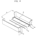
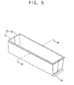
- the baking tray 40 is disposed between the upper kneading drum 64 and the lower kneading drum, and is in a box like shape with a top opening to contain completely kneaded dough. Further, the baking tray 40 may be made of aluminum or steel which has a good heat-resisting property. In lower opposite sides of the baking tray 40 are provided tray holders 60, respectively. As shown in FIG. 4, the tray holders 60 are detachably sliding-combined with tray rails 41 (see FIG. 3) provided in inner opposite sides of the oven 30, respectively.
- the plurality of heaters 70 are, respectively, disposed in upper and lower parts of the door 80 and in upper and lower parts of the oven 30, thereby heating the inside of the oven 30.
- the door 80 is rotatably combined to the main body 20 so as to selectively open and close a front opening of the oven 30.
- the door 60 comprises a window glass 82 allowing a user to view the inside of the oven 30 therethrough.
- the tray 40 comprises a stationary tray 42 having a first profile groove portion 46a provided in a lower section along a lengthwise direction thereof, and a rotatable tray 44 having a second profile groove portion 46b opposite to the first profile groove portion 46a of the stationary tray 42, such that the stationary tray 42 and the rotatable tray 44 are combined to each other to form a box shape with the top opening.
- the first and second groove portions combine to form a profile groove 46.
- One or more profiles 50 are compressively fit into a space formed by the first and second profile groove portions 46a and 46b of the stationary and rotatable trays 42 and 44.
- the tray holders 60 which are used in holding the rotatable tray 44 and allowing the rotatable tray 44 to selectively rotate thereon.
- the tray holders 60 In lower opposite sides of the rotatable tray 44 are protruded a plurality of projections 45 to rotatably combine to the tray holders 60.
- Each of the tray holders 60 is formed with a plurality of guide grooves 62 corresponding to the plurality of projections 45 of the rotatable tray 44.
- the respective first and second profile groove portions 46a and 46b of the stationary and rotatable trays 42 and 44 each have a rectangular cross-section, and are provided with a plurality of breakaway-prevention protrusions 47 securely and compressively supporting partial outer surfaces of the profiles 50 so as to prevent the profiles 50 corresponding to the first and second profile groove portions 46a and 46b from breaking away therefrom.
- the breakaway-prevention protrusions 47 are incorporated with the respective stationary and rotatable trays 42 and 44 by molding, and are plurally provided in inner upper and inner lower edges of each of the first and second profile groove portions 46a and 46b.
- the breakaway-prevention protrusions 47 may vary in a placing position, a number, a size, and a shape thereof as necessary within ranges to securely and compressively support each of the profiles 50.
- the breakaway-prevention protrusions 47 may be integrally formed on the first and second profile groove portions 46a and 46b by a press.
- a bread maker including a molded baking tray with a profile groove is provided, so that work efficiency and productivity are increased.
- the manufacturing cost of the baking tray is reduced, thereby allowing the bread maker to have an advantage in price competitiveness.
Landscapes
- Life Sciences & Earth Sciences (AREA)
- Engineering & Computer Science (AREA)
- Food Science & Technology (AREA)
- Baking, Grill, Roasting (AREA)
Claims (13)
- Machine à pain, comprenant:un corps principal (20);un four (30) logé dans le corps principal (20);un bac de cuisson (40) disposé à l'intérieur du four (30) et pourvu d'une rainure (46) pour le profilé; etau moins un profilé (50) inséré dans la rainure (46) pour profilé du bac de cuisson,caractérisé en ce que la rainure (46) pour profilé du bac de cuisson comporte une pluralité de parties saillantes (47) empêchant un dégagement, formées au niveau des bords de la rainure pour empêcher que le profilé (50) ne se dégage de la rainure (46) pour profilé.
- Machine à pain selon la revendication 1, dans lequel les parties saillantes (47) de la rainure (46) pour profilé, qui empêchent un dégagement, supportent de façon fixe une circonférence extérieure du profilé (50).
- Machine à pain selon la revendication 1 ou la revendication 2, dans lequel il est prévu une pluralité des parties (47), qui empêchent un dégagement, dans les bords supérieur et inférieur de la rainure (46) pour profilé.
- Machine à pain selon l'une quelconque des revendications précédentes, dans lequel les parties saillantes (47) empêchant un dégagement sont formées à la presse dans la rainure (46) pour profilé.
- Machine à pain selon la revendication 1, dans lequel chacun des profilés (50) possède une forme cylindrique.
- Machine à pain selon la revendication 1, dans lequel le bac de cuisson (40) comprend:un bac fixe (42);un bac mobile (44) couplé, de façon mobile, au bac fixe (42).
- Machine à pain selon la revendication 6, dans lequel:le bac fixe (42) comprend:une première partie (46a) de rainure pour profilé, prévue dans une section inférieure du bac et dans la direction longitudinale de ce dernier, etle bac mobile (44) comprend:une second partie (46b) de rainure pour profilé, prévue en vis-à-vis de la première partie (46a) de rainure pour profilé du bac fixe (42) de telle sorte que le bac fixe (42) et le bac mobile (44) peuvent être combinés entre eux.
- Machine à pain selon la revendication 7, dans lequel le profilé ou la pluralité de profilés (50) sont insérés par compression dans un espace formé par les première et seconde parties (46a, 46b) de la rainure pour profilé.
- Machine à pain selon la revendication 7 ou la revendication 8, dans lequel les première et seconde parties (46a et 46b) de la rainure pour profilé des bacs fixe et mobile (42, 44) sont équipées de la pluralité de parties saillantes (47).
- Machine à pain selon la revendication 9, dans lequel les première et seconde parties (46a, 46b) de rainure pour profilé possèdent des sections transversales rectangulaires
- Machine à pain selon la revendication 9 ou la revendication 10, dans lequel la pluralité de parties saillantes (47) sont une pluralité de parties saillantes empêchant un dégagement pour supporter d'une manière fixe et en compression des surfaces extérieures partielles de chacun du profilé ou de la pluralité de profilés (50) afin d'empêcher que le profilé ou la pluralité de profilés (50) correspondant aux première et seconde parties (46a, 46b) de rainure pour profilés ne se dégagent de ces dernières.
- Machine à pain selon la revendication 11, dans lequel les parties saillantes (47) empêchant un dégagement sont incorporées par moulage dans les bacs fixe et mobile (42, 44) et une pluralité de telles parties saillantes sont prévues dans le bord supérieur intérieur et dans le bord inférieur intérieur de chacune des première et seconde parties (46a, 46b) de rainure pour profilé.
- Machine à pain selon la revendication 12, dans lequel les parties (47) empêchant un dégagement sont formées d'un seul tenant sur les première et seconde parties (46a, 46b) de la rainure pour profilé.
Applications Claiming Priority (2)
| Application Number | Priority Date | Filing Date | Title |
|---|---|---|---|
| KR2003029123 | 2003-05-07 | ||
| KR1020030029123A KR20040096244A (ko) | 2003-05-07 | 2003-05-07 | 제빵기 |
Publications (2)
| Publication Number | Publication Date |
|---|---|
| EP1475019A1 EP1475019A1 (fr) | 2004-11-10 |
| EP1475019B1 true EP1475019B1 (fr) | 2006-05-03 |
Family
ID=36442014
Family Applications (1)
| Application Number | Title | Priority Date | Filing Date |
|---|---|---|---|
| EP03256374A Expired - Lifetime EP1475019B1 (fr) | 2003-05-07 | 2003-10-09 | Machine de fabrication de pain |
Country Status (6)
| Country | Link |
|---|---|
| US (1) | US20040221726A1 (fr) |
| EP (1) | EP1475019B1 (fr) |
| JP (1) | JP2004329896A (fr) |
| KR (1) | KR20040096244A (fr) |
| CN (1) | CN1269409C (fr) |
| DE (1) | DE60305005T2 (fr) |
Family Cites Families (6)
| Publication number | Priority date | Publication date | Assignee | Title |
|---|---|---|---|---|
| US4523407A (en) * | 1983-09-23 | 1985-06-18 | Dorothy W. Miller | Hatch cover |
| US4579354A (en) * | 1984-12-05 | 1986-04-01 | Vassallo Research And Development Corporation | Gasket |
| JPH0219114A (ja) * | 1988-07-06 | 1990-01-23 | Matsushita Electric Ind Co Ltd | 自動製パン機 |
| US5146840A (en) * | 1989-11-22 | 1992-09-15 | Heden-Team Ag | Automatic baking apparatus and mixbag therefore |
| US5511518A (en) * | 1994-11-02 | 1996-04-30 | Fel-Pro Incorporated | Sealing assembly with undercut groove |
| TW391867B (en) * | 1997-11-17 | 2000-06-01 | Heden Team Ag | Automatic baking apparatus and mixbag thereof |
-
2003
- 2003-05-07 KR KR1020030029123A patent/KR20040096244A/ko not_active Withdrawn
- 2003-10-09 DE DE60305005T patent/DE60305005T2/de not_active Expired - Lifetime
- 2003-10-09 EP EP03256374A patent/EP1475019B1/fr not_active Expired - Lifetime
- 2003-10-10 CN CNB2003101010248A patent/CN1269409C/zh not_active Expired - Fee Related
- 2003-11-18 US US10/714,610 patent/US20040221726A1/en not_active Abandoned
-
2004
- 2004-03-30 JP JP2004101347A patent/JP2004329896A/ja active Pending
Also Published As
| Publication number | Publication date |
|---|---|
| JP2004329896A (ja) | 2004-11-25 |
| CN1547927A (zh) | 2004-11-24 |
| US20040221726A1 (en) | 2004-11-11 |
| KR20040096244A (ko) | 2004-11-16 |
| CN1269409C (zh) | 2006-08-16 |
| DE60305005T2 (de) | 2006-11-23 |
| DE60305005D1 (de) | 2006-06-08 |
| EP1475019A1 (fr) | 2004-11-10 |
Similar Documents
| Publication | Publication Date | Title |
|---|---|---|
| EP1475019B1 (fr) | Machine de fabrication de pain | |
| EP1382253B1 (fr) | Améliorations apportées aux machines de fabrication de pain | |
| CN219516019U (zh) | 一种烤箱内胆及易清洁烤箱 | |
| EP1474977B1 (fr) | Appareil de cuisson de pain | |
| EP1474976B1 (fr) | Appareil de cuisson de pain | |
| US20040221729A1 (en) | Bread maker | |
| EP2410862B1 (fr) | Appareil de maison pour faire du pain | |
| EP1475020B1 (fr) | Machine de fabrication de pain | |
| US7275479B2 (en) | Bread maker | |
| EP1477064B1 (fr) | Une machine de production de pain | |
| JPH11253093A (ja) | 角形ケーキ用焼き型 | |
| EP1474981B1 (fr) | Améliorations apportées aux machines de fabrication de pain | |
| EP1474980A2 (fr) | Machine de fabrication de pain | |
| EP1474987B1 (fr) | Machine de fabrication de pain | |
| EP1474982B1 (fr) | Machine de fabrication de pain | |
| EP0385675A1 (fr) | Boîtiers tubulaires | |
| KR20030067350A (ko) | 전자레인지의 캐비티구조 | |
| JP2006166772A (ja) | パンの焼き色を抑える焼成方法及びパンの焼き色を抑える焼成用治具 | |
| JP6895161B2 (ja) | 配膳車 | |
| KR20020061407A (ko) | 제빵기 | |
| KR20020061409A (ko) | 제빵기 | |
| JP2002102073A (ja) | 自動製パン機 | |
| JP2002065471A (ja) | 自動製パン機 | |
| EP1474978A1 (fr) | Appareil de cuisson de pain | |
| HK1091385B (en) | Removable liner and electric oven using the liner |
Legal Events
| Date | Code | Title | Description |
|---|---|---|---|
| PUAI | Public reference made under article 153(3) epc to a published international application that has entered the european phase |
Free format text: ORIGINAL CODE: 0009012 |
|
| 17P | Request for examination filed |
Effective date: 20031009 |
|
| AK | Designated contracting states |
Kind code of ref document: A1 Designated state(s): AT BE BG CH CY CZ DE DK EE ES FI FR GB GR HU IE IT LI LU MC NL PT RO SE SI SK TR |
|
| AX | Request for extension of the european patent |
Extension state: AL LT LV MK |
|
| 17Q | First examination report despatched |
Effective date: 20050117 |
|
| GRAP | Despatch of communication of intention to grant a patent |
Free format text: ORIGINAL CODE: EPIDOSNIGR1 |
|
| AKX | Designation fees paid |
Designated state(s): DE FR GB SE |
|
| GRAS | Grant fee paid |
Free format text: ORIGINAL CODE: EPIDOSNIGR3 |
|
| GRAA | (expected) grant |
Free format text: ORIGINAL CODE: 0009210 |
|
| AK | Designated contracting states |
Kind code of ref document: B1 Designated state(s): DE FR GB SE |
|
| REG | Reference to a national code |
Ref country code: GB Ref legal event code: FG4D |
|
| REF | Corresponds to: |
Ref document number: 60305005 Country of ref document: DE Date of ref document: 20060608 Kind code of ref document: P |
|
| REG | Reference to a national code |
Ref country code: SE Ref legal event code: TRGR |
|
| ET | Fr: translation filed | ||
| PLBE | No opposition filed within time limit |
Free format text: ORIGINAL CODE: 0009261 |
|
| STAA | Information on the status of an ep patent application or granted ep patent |
Free format text: STATUS: NO OPPOSITION FILED WITHIN TIME LIMIT |
|
| 26N | No opposition filed |
Effective date: 20070206 |
|
| PGFP | Annual fee paid to national office [announced via postgrant information from national office to epo] |
Ref country code: DE Payment date: 20101006 Year of fee payment: 8 |
|
| PGFP | Annual fee paid to national office [announced via postgrant information from national office to epo] |
Ref country code: GB Payment date: 20110921 Year of fee payment: 9 Ref country code: SE Payment date: 20110919 Year of fee payment: 9 Ref country code: FR Payment date: 20111004 Year of fee payment: 9 |
|
| GBPC | Gb: european patent ceased through non-payment of renewal fee |
Effective date: 20121009 |
|
| REG | Reference to a national code |
Ref country code: FR Ref legal event code: ST Effective date: 20130628 |
|
| PG25 | Lapsed in a contracting state [announced via postgrant information from national office to epo] |
Ref country code: SE Free format text: LAPSE BECAUSE OF NON-PAYMENT OF DUE FEES Effective date: 20121010 Ref country code: GB Free format text: LAPSE BECAUSE OF NON-PAYMENT OF DUE FEES Effective date: 20121009 Ref country code: DE Free format text: LAPSE BECAUSE OF NON-PAYMENT OF DUE FEES Effective date: 20130501 |
|
| REG | Reference to a national code |
Ref country code: DE Ref legal event code: R119 Ref document number: 60305005 Country of ref document: DE Effective date: 20130501 |
|
| PG25 | Lapsed in a contracting state [announced via postgrant information from national office to epo] |
Ref country code: FR Free format text: LAPSE BECAUSE OF NON-PAYMENT OF DUE FEES Effective date: 20121031 |