EP1475574A2 - Plancher ventilé avec un panneau de plancher et sa méthode de fabrication - Google Patents
Plancher ventilé avec un panneau de plancher et sa méthode de fabrication Download PDFInfo
- Publication number
- EP1475574A2 EP1475574A2 EP04076100A EP04076100A EP1475574A2 EP 1475574 A2 EP1475574 A2 EP 1475574A2 EP 04076100 A EP04076100 A EP 04076100A EP 04076100 A EP04076100 A EP 04076100A EP 1475574 A2 EP1475574 A2 EP 1475574A2
- Authority
- EP
- European Patent Office
- Prior art keywords
- floorboard
- ducts
- floor
- ventilation space
- ventilated
- Prior art date
- Legal status (The legal status is an assumption and is not a legal conclusion. Google has not performed a legal analysis and makes no representation as to the accuracy of the status listed.)
- Withdrawn
Links
- 238000004519 manufacturing process Methods 0.000 title description 4
- 238000009423 ventilation Methods 0.000 claims abstract description 33
- 238000009408 flooring Methods 0.000 claims abstract description 14
- 238000004891 communication Methods 0.000 claims abstract description 11
- 238000000034 method Methods 0.000 claims abstract description 5
- 125000006850 spacer group Chemical group 0.000 claims description 11
- 239000003570 air Substances 0.000 description 22
- 239000004033 plastic Substances 0.000 description 8
- 239000011093 chipboard Substances 0.000 description 4
- 238000010276 construction Methods 0.000 description 4
- 238000003754 machining Methods 0.000 description 4
- 239000000463 material Substances 0.000 description 4
- 229910052704 radon Inorganic materials 0.000 description 4
- SYUHGPGVQRZVTB-UHFFFAOYSA-N radon atom Chemical compound [Rn] SYUHGPGVQRZVTB-UHFFFAOYSA-N 0.000 description 4
- 230000000630 rising effect Effects 0.000 description 4
- 239000000853 adhesive Substances 0.000 description 2
- 230000001070 adhesive effect Effects 0.000 description 2
- 239000003795 chemical substances by application Substances 0.000 description 2
- 239000002985 plastic film Substances 0.000 description 2
- 229920006255 plastic film Polymers 0.000 description 2
- 239000004014 plasticizer Substances 0.000 description 2
- 239000004576 sand Substances 0.000 description 2
- 238000007789 sealing Methods 0.000 description 2
- XLYOFNOQVPJJNP-UHFFFAOYSA-N water Substances O XLYOFNOQVPJJNP-UHFFFAOYSA-N 0.000 description 2
- 241000233866 Fungi Species 0.000 description 1
- 239000012080 ambient air Substances 0.000 description 1
- 230000001580 bacterial effect Effects 0.000 description 1
- 239000004566 building material Substances 0.000 description 1
- 229910003460 diamond Inorganic materials 0.000 description 1
- 239000010432 diamond Substances 0.000 description 1
- 238000005553 drilling Methods 0.000 description 1
- 238000005516 engineering process Methods 0.000 description 1
- 238000000605 extraction Methods 0.000 description 1
- 239000000945 filler Substances 0.000 description 1
- 239000011440 grout Substances 0.000 description 1
- 238000009413 insulation Methods 0.000 description 1
- 239000011159 matrix material Substances 0.000 description 1
- 238000013508 migration Methods 0.000 description 1
- 230000005012 migration Effects 0.000 description 1
- 239000011368 organic material Substances 0.000 description 1
- 239000011236 particulate material Substances 0.000 description 1
- 239000000565 sealant Substances 0.000 description 1
- 239000007787 solid Substances 0.000 description 1
- 239000000758 substrate Substances 0.000 description 1
- 230000007704 transition Effects 0.000 description 1
Images



Classifications
-
- F—MECHANICAL ENGINEERING; LIGHTING; HEATING; WEAPONS; BLASTING
- F24—HEATING; RANGES; VENTILATING
- F24F—AIR-CONDITIONING; AIR-HUMIDIFICATION; VENTILATION; USE OF AIR CURRENTS FOR SCREENING
- F24F7/00—Ventilation
- F24F7/04—Ventilation with ducting systems, e.g. by double walls; with natural circulation
- F24F7/06—Ventilation with ducting systems, e.g. by double walls; with natural circulation with forced air circulation, e.g. by fan positioning of a ventilator in or against a conduit
- F24F7/10—Ventilation with ducting systems, e.g. by double walls; with natural circulation with forced air circulation, e.g. by fan positioning of a ventilator in or against a conduit with air supply, or exhaust, through perforated wall, floor or ceiling
-
- E—FIXED CONSTRUCTIONS
- E04—BUILDING
- E04F—FINISHING WORK ON BUILDINGS, e.g. STAIRS, FLOORS
- E04F15/00—Flooring
- E04F15/02—Flooring or floor layers composed of a number of similar elements
- E04F15/024—Sectional false floors, e.g. computer floors
- E04F15/02405—Floor panels
-
- F—MECHANICAL ENGINEERING; LIGHTING; HEATING; WEAPONS; BLASTING
- F24—HEATING; RANGES; VENTILATING
- F24F—AIR-CONDITIONING; AIR-HUMIDIFICATION; VENTILATION; USE OF AIR CURRENTS FOR SCREENING
- F24F2221/00—Details or features not otherwise provided for
- F24F2221/40—HVAC with raised floors
Definitions
- the present invention relates to a ventilated floor comprising a sub-floor, a duct- or gap forming device for realising a ventilation space along the sub-floor, a structural layer which rests on the duct- or gap forming device, the structural layer displaying, on its upper side, a flooring or itself constituting such a flooring, means for the supply of air to the ventilation space and means for exhausting air from the ventilation space.
- the present invention also relates to a floorboard designed, in a ventilated floor, to rest with its underside on spacers which, between a sub-floor and the underside of the floorboard, form a ventilation space and, with their upper side, support a flooring or themselves constitute such a flooring.
- the present invention further relates to a method of manufacturing a floorboard designed so as to form part of a ventilated floor.
- Ventilated floors have been employed in many different contexts, principally in attempts to ventilate off residual smell in floors and ground plates and to prevent damp in the sub-floor from rising to superjacent constructions and causing damage.
- slab on the ground in which event the concrete slab is either in direct contact with the ground or rests on an insulation.
- the concrete slab will often be uneven in its surface and before an inner floor can be provided thereon the surface is screeded with filler grout which often contains organic material.
- screeding may be effected with a layer of fine particulate material, for example sand, whereon a plastic layer is possibly provided as a damp course.
- a nailed substrate such as a chipboard panelling is provided in order to give support for the inner flooring, for example a parquet floor.
- the plastic layer is usually insufficiently moisture tight to prevent damp from rising up into the chipboard panelling and also into the inner flooring.
- water under high pressure may penetrate up through the concrete slab and be absorbed by the sand and further upwards into the nailed layer which is destroyed and begins to rot.
- a further field of practical application for ventilation floors is in buildings which are erected in areas where there is a high radon content in the bedrock.
- the only method of reducing the concentration of radon indoors is to increase the indoor ventilation among other things using ventilation devices such as ventilated floors.
- the problems inherent in radon may be particularly severe in buildings where a basement wall is manufactured from a radon-emitting material, such as certain types of lightweight concrete.
- the so-called platon mat consists of a thick plastic film on whose one side projections are provided in a diamond pattern. The projections rest on the sub-floor so that a ventilation space is formed between this floor and the underside of the thick plastic film.
- Patent Specification SE-B-446 022 discloses a ventilated floor with floorboards which rest on a so-called platon mat.
- the ducts between the projections are in communication with the surroundings via a closed profile which is interconnected to an extraction fan and which is disposed as a flooring lining along a wall.
- the floor also displays a passage for incoming air through a filter which is disposed along an opposing wall.
- the air current in such a design will not be uniformly distributed, since the air flow is often greater at that end of the floor where the fan is located.
- the present invention has for its object to design the ventilation floor and floorboard intimated by way of introduction so that they obviate the drawbacks inherent in prior art technology.
- the present invention has for its object to design the device according to the invention in such a manner that a uniform flow pattern beneath the entire floor surface is realised and that the load-carrying capacity of the floor is increased.
- the present invention further has for its object to design the device according to the invention so that the building height of the floor may be kept within reasonable limits.
- the ventilated floor intimated by way of introduction is characterised in that the structural layer includes, along a first wall connecting to the sub-floor, a floorboard which has a number of ducts disposed in its interior and directed along the first wall, the ducts being closed towards the upper side of the floorboard and being in communication with the ventilation space by the intermediary of a number of apertures, and that the ducts are in communication with means for the exhausting of air.
- the floorboard described by way of introduction is characterised in that the floorboard displays a number of ducts which are disposed in its interior and which extend between two opposing edges of the floorboard, and that the ducts are in flow communication with the underside of the floorboard by the intermediary of a number of apertures, while the ducts are closed towards the upper side of the floorboard.
- the invention relates to a ventilated floor which is intended to ventilate off residual smell in floors and ground plates and to prevent damp in the sub-floor from rising up to superjacent constructions.
- the ventilated floor may also have for its purpose to remove radon from subjacent ground or from building materials.
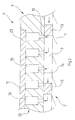
- the ventilated floor 19, which is shown in Fig. 1, has a structural layer which includes both floorboards 9 with a duct system 20 and homogeneous floorboards 18 with no duct system. These two types of floorboards 9 and 18 are then assembled together to form a structural or supporting floor 19, the floorboards 9 with the duct system 20 being disposed in sequence after one another along a first wall 7 in the room and homogeneous floorboards 18 being laid on the remaining floor surface.
- the ventilation space 13 occurs when the floorboards 9 and 18 rest on a duct- or gap forming device 2, the ventilation space 3 being connected to the ambient air of the room by the intermediary of means 5 for the supply of air. These means are disposed along a second wall 8 in the room.
- the ventilation space 3 is, by the intermediary of a number of apertures 12, in communication with a duct system 20 in the floorboards 9 and with a ventilation device. Between the ventilation space 3 and the duct system 20 in the floorboards 9, there occurs a partial vacuum, which entails circulation of the air in the ventilation space 3.
- the ventilation device is a mechanical device which gives rise to a flow pattern uniformly distributed over the entire floor surface and air flows transversely across the room from the longitudinal second wall 8 of the room to the opposing longitudinal first wall 7 in accordance with the flow arrows 15, 16 and 17 in Fig. 1.
- the assembled floor 19, which is assembled from the different floorboards 9 and 18, is shown in Fig. 1.
- the ventilated floorboards 9 with the duct system 20 are preferably disposed with their longitudinal edges along the longitudinal first wall 7 in a room.
- the next ventilated floorboard 9 is disposed adjacent the transverse edge of the first floorboard 9, along the first wall 7, whereafter several ventilated floorboards 9 may be disposed in sequence after one another and form a long row.
- Adjacent the row of the ventilated floorboards 9, homogeneous floorboards 18 are disposed with their longitudinal sides along the longitudinal sides of the ventilated floorboards 9.
- the homogeneous floorboards 18 may be disposed in a plurality of rows adjacent one another's longitudinal sides until the whole floor surface is covered.
- the assembled ventilated floorboards 9 with the duct system 20 and the homogeneous floorboards 18 without the system are manufacture from a mechanically durable material such as, for example, a chipboard an MDF or HDF panelling.
- the floorboards 9 and 18 are treated with an agent to prevent the floorboards 9 and 18 from attracting damp and moisture.
- the ventilation device includes means 5 for the supply of air, for example through a filter 21 or a floor lining with recesses for incoming air, which is connected to the ventilation space 3 along the entire longitudinal second wall 8 with homogeneous floorboards 18 and means for exhausting air 6, for example an extractor fan 22 which is connected to the duct system 20 at a transverse edge of the row of the ventilated floorboards 9.
- the ducts in the opposing edge of the row of floorboards 9 are blocked, for example by plugs, so as to create a tight system.
- the extractor fan 22 for outgoing air is in communication with all ducts 10 in the duct system 20.
- the devices for incoming and outgoing air 21 and 22 are preferably disposed on two of the opposing longitudinal sides of the room, this in order to create a uniform air current beneath the floor in the ventilation space 3.
- the air flows in a pattern from the second wall 8 to the first wall 7, where the flow lines 15 of the air are substantially parallel with each other, according to Fig. 1.
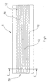
- the ventilated floorboard 9, which is shown in Figs. 4 and 5, has a duct system 20 which displays a plurality of ducts 10 which each have at least one through-going aperture 12, permitting circulation of air from the ventilation space 3 beneath the floor up to the duct system 20.
- the duct system 20 is closed on the top side 11 of the floorboard by a homogeneous top board 23 which stabilises the floorboard 9 and is disposed in a recess 24 over the duct system 20 and by such means forms a part of the structural layer 4 of the floorboard 9.
- the recess 24 is of a depth that corresponds to the thickness of the top board 23, whereby the floorboard 9 displays a smooth and uniform top side also over the duct system 20.
- the floorboard 9 and the top board 23 are manufactured from the same material so as to avoid deformations in the floorboard depending on variations in the moisture content in the two boards. Finally, the top board 23 is glued in the recess.
- the duct system 20 of the floorboard 9 which is shown partly in Fig. 5 accommodates a plurality of ducts 10, for example by machining, in the central region of the floorboard 9.
- the ducts 10 extend substantially parallel with the edges of the floorboard 9 from the one transverse edge of the floorboard 9 to the opposing, second transverse of the floorboard 9.
- On machining of the upwardly open ducts 10 a portion is left intact in the lower region of the floorboard 9 which imparts rigidity to the floorboard 9.
- an intact portion is also left of both edges of the floorboard 9 in order that the floorboard 9 will retain its stability.
- the ducts discharge in the bottom of the recess 24 before this is closed by means of the top board 23.
- the recess 24 is also machined from the upper side of the floorboard 9. The sequence between the machining of the recess 24 and the ducts 10 is determined for reasons of production engineering.
- the apertures 12 are disposed vertically through the lower intact portion of the duct system 20, for example by drilling, in a diagonally transverse pattern between two opposing comers of the floorboard 9. It is vital that the surface area of the apertures 12 is considerably less than the surface area of the ventilation ducts 10 in order to ensure a reliable flow through all apertures 12 and thereby realise the sought-for uniform and all-covering flow pattern according to Figs. 1 and 6.
- Fig. 5 shows a row of diagonally disposed apertures 12 in the bottoms of the ducts 10. This implies that the apertures 12 in adjacent ducts are offset in relation to one another in the longitudinal direction of the ducts, and possibly more than one row of diagonally placed apertures 12 may be provided in the duct system 20.
- the underside 14 of the floorboard 9 rests on duct- or gap forming devices 2, for example spacers 13 which support the floorboards 9 and 18 and are disposed in a pattern so as to support and stabilise the floorboards 9 and 18.
- the number of spacers required depends on how great the loading the floor 19 is assumed to withstand, the greater the number of spacers 13, the higher can be the loading that the assembled floor 19 can be subjected to.
- the spacers 13 are also disposed in the transitions between the floorboards 9 and 18 at the joints.
- the spacers 13 are, for example, loose, solid plastic spacers which may be fixedly glued beforehand or otherwise secured on the undersides of the floorboards 9 and 18. Possibly, the spacers 13 may be disposed with closer spacing beneath the duct systems 20.
- jointing elements for example tongue and groove edges, which interconnect the floorboards 9 and 18 with each other.
- these joints may also be sealed by a sealant, sealing strip or other sealing agent, or, quite simply, be glued together.
- the homogeneous floorboard 18 without duct system is a board which ahs the same outer dimensions and appearance as the above-described ventilated floorboard 9 in order that they be able to be readily joined together.
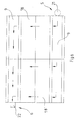
- Fig. 6 One alternative embodiment of the device according to the present invention, in the assembled state, is shown in Fig. 6.
- the floorboards 9 and 18 are constructed in the same manner as above, but are laid out in a different pattern.
- the floorboards 9 with the duct system 20 are disposed along the first and second longitudinal walls 7 and 8 of the room, according to Fig. 6, the means for the supply of air 5 being disposed adjacent the short side of the one row of floorboards 9 and the means for exhausting air 6 being disposed on the opposing side of the room adjacent the second short side of the row of floorboards 9.
Landscapes
- Engineering & Computer Science (AREA)
- Architecture (AREA)
- General Engineering & Computer Science (AREA)
- Civil Engineering (AREA)
- Structural Engineering (AREA)
- Chemical & Material Sciences (AREA)
- Combustion & Propulsion (AREA)
- Mechanical Engineering (AREA)
- Floor Finish (AREA)
- Building Environments (AREA)
- Bathtub Accessories (AREA)
- Duct Arrangements (AREA)
Applications Claiming Priority (2)
| Application Number | Priority Date | Filing Date | Title |
|---|---|---|---|
| SE0301380A SE525138C2 (sv) | 2003-05-09 | 2003-05-09 | Ventilerat golv, däri ingående golvskiva samt förfarande för tillverkning av en sådan |
| SE0301380 | 2003-05-09 |
Publications (2)
| Publication Number | Publication Date |
|---|---|
| EP1475574A2 true EP1475574A2 (fr) | 2004-11-10 |
| EP1475574A3 EP1475574A3 (fr) | 2009-08-12 |
Family
ID=20291278
Family Applications (1)
| Application Number | Title | Priority Date | Filing Date |
|---|---|---|---|
| EP04076100A Withdrawn EP1475574A3 (fr) | 2003-05-09 | 2004-04-13 | Plancher ventilé avec un panneau de plancher et sa méthode de fabrication |
Country Status (3)
| Country | Link |
|---|---|
| EP (1) | EP1475574A3 (fr) |
| NO (1) | NO326581B1 (fr) |
| SE (1) | SE525138C2 (fr) |
Cited By (4)
| Publication number | Priority date | Publication date | Assignee | Title |
|---|---|---|---|---|
| CZ306449B6 (cs) * | 2015-12-18 | 2017-01-25 | ÄŚeskĂ© vysokĂ© uÄŤenĂ technickĂ© v Praze, KloknerĹŻv Ăşstav | Podvětrávaná prefabrikovaná podlaha pro systém podlahového vytápění |
| US9803356B2 (en) | 2013-03-08 | 2017-10-31 | Terra Vent Systems Inc. | Radon gas mitigation systems and apparatus |
| JP2019158179A (ja) * | 2018-03-08 | 2019-09-19 | 株式会社Lixil | 空調システム |
| CN113669831A (zh) * | 2021-09-23 | 2021-11-19 | 苏州大学 | 一种被动房中的均匀通风管路及排风地板 |
Citations (1)
| Publication number | Priority date | Publication date | Assignee | Title |
|---|---|---|---|---|
| SE446022B (sv) | 1984-10-30 | 1986-08-04 | Peter Af Klinteberg | Ventilerat golv |
Family Cites Families (3)
| Publication number | Priority date | Publication date | Assignee | Title |
|---|---|---|---|---|
| JPH07139030A (ja) * | 1993-11-18 | 1995-05-30 | Sekisui Chem Co Ltd | 床パネル |
| SE513398C2 (sv) * | 1999-01-13 | 2000-09-11 | Nivell System Ab | Luftfördelningsanordning i ett ventilationssystem |
| US6676506B2 (en) * | 2000-03-23 | 2004-01-13 | Bengt Steneby | Method and apparatus for ventilation of foundations |
-
2003
- 2003-05-09 SE SE0301380A patent/SE525138C2/sv unknown
-
2004
- 2004-04-13 EP EP04076100A patent/EP1475574A3/fr not_active Withdrawn
- 2004-04-15 NO NO20041547A patent/NO326581B1/no not_active IP Right Cessation
Patent Citations (1)
| Publication number | Priority date | Publication date | Assignee | Title |
|---|---|---|---|---|
| SE446022B (sv) | 1984-10-30 | 1986-08-04 | Peter Af Klinteberg | Ventilerat golv |
Cited By (5)
| Publication number | Priority date | Publication date | Assignee | Title |
|---|---|---|---|---|
| US9803356B2 (en) | 2013-03-08 | 2017-10-31 | Terra Vent Systems Inc. | Radon gas mitigation systems and apparatus |
| US10060121B2 (en) | 2013-03-08 | 2018-08-28 | Terra Vent Systems Inc. | Radon gas mitigation systems and apparatus |
| CZ306449B6 (cs) * | 2015-12-18 | 2017-01-25 | ÄŚeskĂ© vysokĂ© uÄŤenĂ technickĂ© v Praze, KloknerĹŻv Ăşstav | Podvětrávaná prefabrikovaná podlaha pro systém podlahového vytápění |
| JP2019158179A (ja) * | 2018-03-08 | 2019-09-19 | 株式会社Lixil | 空調システム |
| CN113669831A (zh) * | 2021-09-23 | 2021-11-19 | 苏州大学 | 一种被动房中的均匀通风管路及排风地板 |
Also Published As
| Publication number | Publication date |
|---|---|
| SE525138C2 (sv) | 2004-12-07 |
| EP1475574A3 (fr) | 2009-08-12 |
| SE0301380L (sv) | 2004-11-10 |
| NO20041547L (no) | 2004-11-10 |
| NO326581B1 (no) | 2009-01-12 |
| SE0301380D0 (sv) | 2003-05-09 |
Similar Documents
| Publication | Publication Date | Title |
|---|---|---|
| US6918215B2 (en) | Free floating sub-floor panel | |
| US20080127593A1 (en) | Moisture-resistant cover floor system for concrete floors | |
| EP1611302B1 (fr) | Modele de construction de piscine modulaire | |
| US20110047898A1 (en) | Building components and the buildings constructed therewith | |
| US6164026A (en) | Raised access floor | |
| EP1475574A2 (fr) | Plancher ventilé avec un panneau de plancher et sa méthode de fabrication | |
| US3624978A (en) | Monolithic structural member for foundation or ceiling system | |
| US20250137266A1 (en) | Insulated Floor System for Grade or Basement Floors | |
| CA1298090C (fr) | Fondation pour batiments de bois et methode de construction connexe | |
| EP1083269B1 (fr) | Aides pour la pose de revêtements en plaques en position surélevée ou ventilée | |
| DE69828622T2 (de) | Wandstützeinrichtung | |
| US20140013694A1 (en) | Free floating sub-floor thermoplastic tile | |
| US8132377B2 (en) | Floor coverings with wooden floors on a substrate, method for the covering of a substrate and use of studded plates | |
| US20060257210A1 (en) | Residential basement flooring system and method using pier capitals for supporting pre-cast slabs | |
| WO2001057329A1 (fr) | Couche structurelle de plancher et paroi | |
| KR101707956B1 (ko) | 데크플레이트를 이용한 강구조 건축물 시공방법 | |
| CN1218101C (zh) | 一种模板构件和由该模板构件构成的模制墙或双层墙 | |
| WO2017056602A1 (fr) | Procédé pour construction d'extrémité supérieure de fondations en béton, et coffrage d'extrémité supérieure | |
| EP1309761B1 (fr) | Système de revêtement de sol avec un revêtement de sol et des panneaux de sous-plancher | |
| GB2106158A (en) | Permanent formwork | |
| JP4364045B2 (ja) | 建造物の施工方法及び建造物 | |
| US9970200B1 (en) | Raised adjustable insulated flooring system | |
| JP2935359B1 (ja) | 建築用下地板 | |
| JPH028980Y2 (fr) | ||
| AU739647B2 (en) | Building construction |
Legal Events
| Date | Code | Title | Description |
|---|---|---|---|
| PUAI | Public reference made under article 153(3) epc to a published international application that has entered the european phase |
Free format text: ORIGINAL CODE: 0009012 |
|
| AK | Designated contracting states |
Kind code of ref document: A2 Designated state(s): AT BE BG CH CY CZ DE DK EE ES FI FR GB GR HU IE IT LI LU MC NL PL PT RO SE SI SK TR |
|
| AX | Request for extension of the european patent |
Extension state: AL HR LT LV MK |
|
| RAP1 | Party data changed (applicant data changed or rights of an application transferred) |
Owner name: HERTIG KNUT AB |
|
| PUAL | Search report despatched |
Free format text: ORIGINAL CODE: 0009013 |
|
| AK | Designated contracting states |
Kind code of ref document: A3 Designated state(s): AT BE BG CH CY CZ DE DK EE ES FI FR GB GR HU IE IT LI LU MC NL PL PT RO SE SI SK TR |
|
| AX | Request for extension of the european patent |
Extension state: AL HR LT LV MK |
|
| RIC1 | Information provided on ipc code assigned before grant |
Ipc: E04F 15/024 20060101ALI20090707BHEP Ipc: F24F 7/10 20060101AFI20040726BHEP |
|
| AKX | Designation fees paid | ||
| REG | Reference to a national code |
Ref country code: DE Ref legal event code: 8566 |
|
| STAA | Information on the status of an ep patent application or granted ep patent |
Free format text: STATUS: THE APPLICATION IS DEEMED TO BE WITHDRAWN |
|
| 18D | Application deemed to be withdrawn |
Effective date: 20100213 |