EP1475994A2 - Cerumenschutzeinrichtung - Google Patents
Cerumenschutzeinrichtung Download PDFInfo
- Publication number
- EP1475994A2 EP1475994A2 EP04009535A EP04009535A EP1475994A2 EP 1475994 A2 EP1475994 A2 EP 1475994A2 EP 04009535 A EP04009535 A EP 04009535A EP 04009535 A EP04009535 A EP 04009535A EP 1475994 A2 EP1475994 A2 EP 1475994A2
- Authority
- EP
- European Patent Office
- Prior art keywords
- protection device
- knobs
- cerumen protection
- cerumen
- sound
- Prior art date
- Legal status (The legal status is an assumption and is not a legal conclusion. Google has not performed a legal analysis and makes no representation as to the accuracy of the status listed.)
- Withdrawn
Links
Images

Classifications
-
- H—ELECTRICITY
- H04—ELECTRIC COMMUNICATION TECHNIQUE
- H04R—LOUDSPEAKERS, MICROPHONES, GRAMOPHONE PICK-UPS OR LIKE ACOUSTIC ELECTROMECHANICAL TRANSDUCERS; ELECTRIC HEARING AIDS; PUBLIC ADDRESS SYSTEMS
- H04R25/00—Electric hearing aids
- H04R25/65—Housing parts, e.g. shells, tips or moulds, or their manufacture
- H04R25/652—Ear tips; Ear moulds
- H04R25/654—Ear wax retarders
Definitions
- the invention relates to a cerumen protection device for a Hearing aid device, the at least one microphone, an amplifier unit and comprises a handset, with those picked up by the microphone Sound signals amplified in the amplifier unit, converted into acoustic signals by the listener and via a Sound channel are delivered to the eardrum and where all or part of the wax guard in the Sound channel can be used.
- a wax protection device is known from WO 00/03561, which are interchangeable in the sound outlet opening Hearing aid inserted and removed again can.
- the cerumen protection device essentially has one cylindrical outer shape and is provided with a bead, through which the cerumen protection device in one Sound tube is attached.
- a disadvantage of this fastening method is the uneven force curve, which in Inserting and removing the wax guard in the sound tube is exerted on the sound tube. in the In the worst case, this can lead to the Sound tube from the housing of the hearing aid in the area the sound outlet opens.
- the bead can also be closed a kind of memory effect in the sound tube. Thereby there is a permanent deformation of the sound tube in the area of the bead. However, this worsens the attachment the wax guard in the sound tube and can even lead to the loss of the same.
- US 5,864,628 and US 5,712,918 are also cerumen protection devices known in the area of the sound outlet a hearing aid in a sound tube can be introduced and removed again.
- the front end of the known cerumen protection device is frustoconical tapers what the insertion of the wax guard relieved in the sound tube. Further points the front end has a larger diameter than the rest, Part of the cerumen protection device that can be inserted into the sound tube.
- This too similar to the WO 00/03561, a type of bulge formed in the sound tube intervenes and the attachment of the cerumen protection device in the sound tube. It therefore follows here too the disadvantages mentioned in WO 00/03561.
- the object of the present invention is the attachment a wax guard in the sound channel of a hearing aid to improve.
- This task is performed with a cerumen protection device for a Hearing aid device, the at least one microphone, an amplifier unit and comprises a handset, with those picked up by the microphone Sound signals amplified in the amplifier unit, converted into acoustic signals by the listener and via a Sound channel are delivered to the eardrum and where all or part of the wax guard in the Sound channel can be used, solved by having a surface the wax guard for attachment in the Sound channel is provided with several knobs on one smooth surface of the sound channel and due to the Generate friction holding effect.
- the cerumen protection device is preferably cylindrical trained and provided with a through hole so that the sound generated by the listener through the sound channel and the wax guard is directed to the eardrum can.
- the through hole there is advantageously one Cerumen retention device, e.g. as a lattice structure or as a disc-shaped element with a large number of smaller ones Through openings can be formed.
- the wax guard can be used to prevent the earpiece from becoming dirty also perform an acoustic function as a damper, being due in particular to the sound absorbing effect the selection and arrangement of the arranged in the through hole Elements, such as the cerumen retention device, influence can be taken.
- the cerumen retention device can for complete or partial insertion into the sound channel be formed, whereby for the latter case their diameter at the rear end preferably increased in such a way that a full insertion into the sound channel is prevented.
- the invention has the advantage that when the Cerum protection device to be used in the sound tube Force rises steadily until the wax guard has finally reached its final position. This prevents the sound tube from being in the area the sound outlet opening from the housing of the hearing aid solves. In addition, it is very unlikely that when removing and reinserting the wax guard the knobs in the same place as before come to rest. This prevents a memory effect and the wax guard remains after a long time Use still securely attached in the sound channel.
- knobs can influence the force curve when inserting the cerumen protection device be placed in the sound tube.
- One embodiment of the invention thus provides that the Counter density along the insertable housing area the direction of insertion increases. This means that in the front Area of the cerumen protection device, which is first in the Sound channel is introduced, fewer knobs are present than in a rear area of the cerumen protection device. The one to be used to insert the cerumen protection device This increases force evenly.
- Another embodiment of the invention provides that the Knob height between the front area and the rear area the wax guard varies.
- the nub height is proportional low compared to the knob height in the rear area. This can also result in a steady increase in the rate at which the Cerium protection device force to be exerted.
- one embodiment provides the invention specially designed knobs through which for inserting the cerumen protection device into the sound channel a relatively small force compared to the force for Removal of the wax guard from the sound channel must be used. This is done, for example, by that the pimples, starting from the normal surface the wax guard, against the insertion direction gradually and steadily increase, then from the maximum The height of the knobs abruptly returns to the normal surface level falling back.
- the knobs can also be in the direction of insertion have a tapered course.
- the knobs are formed semi-conical, the cone tip shows in the direction of insertion.
- FIG. 1 shows the front, proximal end of one in the ear portable hearing aid and a wax guard
- the hearing aid that can be worn in the ear 1 comprises a housing 2 with one arranged in the housing Sound outlet opening 3. Inside the housing 2 a receiver 4 is arranged, which is connected via a sound tube 5 is connected to the sound outlet opening 3. Usually is the sound tube 5 in the area of the sound outlet opening 3 by a fastener, e.g. an adhesive 6, attached to the housing 2 of the hearing aid 1.
- a fastener e.g. an adhesive 6, attached to the housing 2 of the hearing aid 1.
- Cerum protection device 7 is provided, some of which in the Sound tube 5 can be inserted. This is essentially tubular to receive the sound from the handset 4 to be able to forward into the auditory canal of a hearing aid wearer.
- the outer diameter corresponds to the tubular Cerumen protection device 7 approximately the inner diameter of the Sound tube 5.
- Cerumen protection device 7 includes the wax guard 7 inside a lattice structure 8 with small ones Sound passage openings.
- a projection 9 formed, the one complete insertion of the cerumen protection device 7 into the Sound tube 5 prevented. If necessary, at this Cantilever 9 also a suitable tool for pulling out the wax guard 7 from the sound tube 5 become.
- cerumen protection device 7 An inserted cerumen protection device 7 must be in this way attached to the hearing aid 1 and in particular the sound tube 5 be an unintentional detachment from that Hearing aid 1 can be excluded under normal circumstances can. Therefore, the cerumen protection device 7 with a circumferential bead 10 provided so that a friction connection created with the sound tube 5.
- the disadvantage of this arrangement is the sudden increase in force in the area in which the bead 10 in the sound tube 5 arrives. In the worst case, this can lead to that the sound tube 5 is in the area of the sound outlet opening 3 detaches from the housing 2 of the hearing aid 1, e.g. by separating the adhesive connection 6. Furthermore a disadvantage of this arrangement is that the bead 10 at used cerumen protection device 7 always on the same Place of the sound tube 5 comes to rest and thereby one permanent deformation of the sound tube 5 on this Digit is the consequence (memory effect).
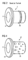
- Figure 2 shows the cerumen protection device 7 according to the state of technology in a three-dimensional view.
- the cylindrical one Surface is provided with a circumferential bead 10, the for fastening the cerumen protection device 7 in the sound tube 5 serves.
- the projection 9 can also be seen to prevent full insertion into the sound channel and the through hole 11.
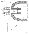
- FIG. 3 also shows the anterior, proximal one Part of a hearing aid device 21 that can be worn in the ear with a Housing 22, a sound outlet opening 23 in the housing, a receiver 24 arranged inside the housing 22 and one Sound tube 25 for connecting the handset 24 to the Sound outlet opening 23.
- the sound tube 25 by an adhesive connection 26 on the housing 22 be attached.
- the exemplary embodiment of the invention according to FIG. 3 also comprises a cerumen protection device 27, which is largely in a sound tube 25 can be inserted.
- the difference to the state of the art according to Figure 1 is the part of Surface of the cerumen protection device 27, which in the Sound tube 25 is inserted with its surface
- Provide knobs, according to the cut representation Figure 3 shows the knobs 30A-30F.
- the pimples according to the embodiment are irregular over the surface the cerumen protection device 27 distributed.
- the density of the knobs based on the surface the cerumen protection device 27, in the front area less than in the rear area.
- This special design the surface of the cerumen protection device 27 is an almost linearly increasing course of the required Force for inserting the cerumen protection device 27 into the Sound tube 25 reached over the distance S.
- a corresponding one The course of force is also evident from FIG. 3. This avoids an abrupt increase in force could lead to loosening the adhesive connection 26. Further the irregular arrangement of the knobs makes it very unlikely that when changing the cerumen protection device 27 again in their previous position come. Permanent deformation of the sound tube 25 is thus prevented.
- FIG. 4 shows the cerumen protection device according to FIG. 3 in three-dimensional view. That essentially goes tooth-shaped formation of the knobs 30 with a triangular Base area and a tip pointing in the direction of insertion out. Both the size and the density of the knobs 30 on the surface of the cerumen protection device the direction of insertion.
- the knobs 30 in the embodiment are shaped to be at the level of the surface the cerumen protection device 27 begin and in the direction of gradually increase at the rear end of the cerumen protection device 27 and get wider, then abruptly return to the starting level falling back. Towards the front end of the wax guard the knobs run together sharply.
- This Form has the advantage that for insertion of the cerumen protection device 27 in the sound tube 25 a lower force than has to be used to pull it out. This will the insertion easier and an unintentional loosening the cerumen protection device prevented by the sound tube 25.
- knobs 30 in rear area of the cerumen protection device are of course of the same size and only in terms of their density in the rear area increase or with the same density only in its dimension increase in the rear area. Furthermore, both the density as well as the dimension of the knobs throughout area that can be inserted into the sound tube remain the same.
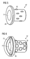
- Figure 5 shows an example of this Cerum protection device 47 with a through hole 51 and A projection 49 has oval knobs 50, the longitudinal direction of which runs parallel to the direction of insertion.
- the pimples in this embodiment are arbitrary on the surface distributed, but with approximately the same density. Furthermore, all knobs 50 are at least approximately the same large.
- a cerumen protection device 67 has a through hole 71 and a projection 69 round nubs 70 on the are also unevenly distributed on the surface.
- the density of the knobs 70 increases in the rear area of the cerumen protection device to.
- the wax guard is another special feature 67 provided with a bracket 72 in the to pull the cerumen protection device out of a Sound channel can intervene a tool.
Landscapes
- Engineering & Computer Science (AREA)
- Physics & Mathematics (AREA)
- Health & Medical Sciences (AREA)
- General Health & Medical Sciences (AREA)
- Neurosurgery (AREA)
- Otolaryngology (AREA)
- Manufacturing & Machinery (AREA)
- Acoustics & Sound (AREA)
- Signal Processing (AREA)
- Headphones And Earphones (AREA)
- Details Of Connecting Devices For Male And Female Coupling (AREA)
- Measurement Of The Respiration, Hearing Ability, Form, And Blood Characteristics Of Living Organisms (AREA)
- Dental Tools And Instruments Or Auxiliary Dental Instruments (AREA)
Abstract
Description
Claims (9)
- Cerumenschutzeinrichtung (27, 47, 67) für ein Hörhilfegerät (1, 21), das wenigstens ein Mikrofon, eine Verstärkereinheit und einen Hörer (4, 24) umfasst, wobei von dem Mikrofon aufgenommene Schallsignale in der Verstärkereinheit verstärkt, durch den Hörer (4, 24) in akustische Signale gewandelt und über einen Schallkanal (5, 25) zum Trommelfell abgegeben werden und wobei die Cerumenschutzeinrichtung (27, 47, 67) ganz oder teilweise in den Schallkanal (5, 25) einsetzbar ist, dadurch gekennzeichnet, dass eine Oberfläche der Cerumenschutzeinrichtung (27, 47, 67) zur Befestigung in dem Schallkanal (5, 25) mit mehreren Noppen (30, 30A - 30F; 50; 70) versehen ist, die an einer glatten Oberfläche des Schallkanals (5,25) anliegen und aufgrund der Reibung Haltewirkung erzeugen.
- Cerumenschutzeinrichtung (27, 47, 67) nach Anspruch 1, dadurch gekennzeichnet, dass die Noppen (30, 30A - 30F; 50; 70) unregelmäßig auf der Oberfläche verteilt sind.
- Cerumenschutzeinrichtung (27, 47, 67) nach Anspruch 1 oder 2, dadurch gekennzeichnet, dass die Dichte der Noppen (30, 30A - 30F; 70) auf der Oberfläche in einer der Einschubrichtung entgegengesetzten Richtung zunimmt.
- Cerumenschutzeinrichtung (27, 47, 67) nach einem der Ansprüche 1 bis 3, dadurch gekennzeichnet, dass die Größe der Noppen (30, 30A - 30F) auf der Oberfläche in einer der Einschubrichtung entgegengesetzten Richtung zunimmt.
- Cerumenschutzeinrichtung (27, 47, 67) nach einem der Ansprüche 1 bis 4, dadurch gekennzeichnet, dass die Noppen (30, 30A - 30F) derart unsymmetrisch geformt sind, dass diese jeweils ausgehend von einem unteren Niveau der Oberfläche der Cerumenschutzeinrichtung (27, 47, 67) entgegen der Einschubrichtung allmählich bis zu einer maximalen Noppenhöhe ansteigen und anschließend abrupt zurück auf das untere Niveau der Oberfläche abfallen.
- Cerumenschutzeinrichtung (27, 47, 67) nach Anspruch 5, dadurch gekennzeichnet, dass die Noppen (30, 30A - 30F) eine im Wesentlichen dreieckige Grundfläche aufweisen, wobei jeweils eine Spitze eines Dreiecks in Einschubrichtung zeigt.
- Cerumenschutzeinrichtung (27, 47, 67) nach einem der Ansprüche 1 bis 4, dadurch gekennzeichnet, dass die Noppen (70) eine im Wesentlichen runde äußere Form aufweisen.
- Cerumenschutzeinrichtung (27, 47, 67) nach einem der Ansprüche 1 bis 4, dadurch gekennzeichnet, dass die Noppen (50) eine im Wesentlichen ovale äußere Form aufweisen.
- Cerumenschutzeinrichtung (57) nach einem der Ansprüche 1 bis 8, gekennzeichnet durch einen in Bezug auf die Einschubrichtung am hinteren Ende der Cerumenschutzeinrichtung (67) angeformten Bügel (72), an den ein Werkzeug zum Herausziehen der Cerumenschutzeinrichtung (67) aus dem Schallkanal (25) angreifen kann.
Applications Claiming Priority (2)
| Application Number | Priority Date | Filing Date | Title |
|---|---|---|---|
| DE10320861A DE10320861B3 (de) | 2003-05-09 | 2003-05-09 | Cerumenschutzeinrichtung |
| DE10320861 | 2003-05-09 |
Publications (2)
| Publication Number | Publication Date |
|---|---|
| EP1475994A2 true EP1475994A2 (de) | 2004-11-10 |
| EP1475994A3 EP1475994A3 (de) | 2008-11-19 |
Family
ID=32981307
Family Applications (1)
| Application Number | Title | Priority Date | Filing Date |
|---|---|---|---|
| EP04009535A Withdrawn EP1475994A3 (de) | 2003-05-09 | 2004-04-22 | Cerumenschutzeinrichtung |
Country Status (4)
| Country | Link |
|---|---|
| US (1) | US7013016B2 (de) |
| EP (1) | EP1475994A3 (de) |
| AU (1) | AU2004201925B2 (de) |
| DE (1) | DE10320861B3 (de) |
Families Citing this family (30)
| Publication number | Priority date | Publication date | Assignee | Title |
|---|---|---|---|---|
| US7793756B2 (en) * | 2005-05-10 | 2010-09-14 | Phonak Ag | Replaceable microphone protective membrane for hearing devices |
| US20080118095A1 (en) * | 2006-11-22 | 2008-05-22 | Fletcher Thomas G | Wax guard for a hearing aid |
| DK2127466T3 (en) * | 2007-03-27 | 2016-09-26 | Sonova Ag | Hearing-aid with microphone protection |
| DE102007037024A1 (de) * | 2007-08-06 | 2009-02-26 | Siemens Medical Instruments Pte. Ltd. | Hörereinrichtung mit elastisch gelagertem Hörer |
| EP2227914A1 (de) * | 2007-10-30 | 2010-09-15 | 3Win N.V. | Am körper getragenes drahtloses wandlermodul |
| US8144910B2 (en) * | 2007-11-14 | 2012-03-27 | Siemens Hearing Instruments, Inc. | Composite receiver tube for a hearing instrument |
| DE102007058987B3 (de) * | 2007-12-07 | 2009-07-16 | Siemens Medical Instruments Pte. Ltd. | Stirnplatte mit Verschlussvorrichtung |
| ES1066993Y (es) * | 2008-01-16 | 2008-07-01 | Valencia Lluis Gomez | Dispositivo de proteccion anticerumen |
| DE102008007553A1 (de) * | 2008-02-05 | 2009-08-13 | Siemens Medical Instruments Pte. Ltd. | Hörgerät mit akustischem Dämpfer |
| US8761424B2 (en) | 2009-06-22 | 2014-06-24 | Shure Acquisition Holdings, Inc. | Earphone sleeve assembly having integral barrier |
| EP2530955A4 (de) * | 2010-01-25 | 2014-08-20 | Jiangsu Betterlife Medical Co Ltd | Ohrform und offenes hörgerät mit empfänger im hörkanal |
| EP2548383B1 (de) | 2010-03-19 | 2014-04-16 | Advanced Bionics AG | Wasserdichtes Gehäuse für akustisches Element und Vorrichtung damit. |
| EP2393311A1 (de) | 2010-06-07 | 2011-12-07 | Sonion A/S | Cerumenfilter für Hörgeräte |
| EP2666306B1 (de) | 2011-01-18 | 2017-03-15 | Advanced Bionics AG | Feuchtigkeitsbeständige kopfstücke und implantierbare cochlear-stimulationssysteme damit |
| US8718307B2 (en) * | 2011-03-11 | 2014-05-06 | Daniel R. Schuamier | Hearing aid apparatus |
| US8820474B2 (en) | 2011-08-25 | 2014-09-02 | Magnatone Hearing Aid Corporation | Ear tip piece for hearing instruments |
| US8800712B2 (en) | 2011-08-25 | 2014-08-12 | Magnatone Hearing Aid Corporation | Ear tip piece for attenuating sound |
| EP2645742B1 (de) * | 2012-03-30 | 2014-12-03 | Oticon A/S | Cerumenfilter and Handhabungsgerät für solche Filter |
| EP2753100B1 (de) * | 2013-01-07 | 2016-01-06 | Oticon A/s | Hörgerätekomponente mit Cerumenfilter |
| WO2015074693A1 (en) * | 2013-11-20 | 2015-05-28 | Phonak Ag | Sound tube for an earpiece, sound tube arrangement, earpiece with such a sound tube or sound tube arrangement and hearing device with such an earpiece |
| JP6060915B2 (ja) * | 2014-02-06 | 2017-01-18 | ソニー株式会社 | イヤピースおよび電気音響変換装置 |
| US9538272B2 (en) * | 2014-09-08 | 2017-01-03 | Apple Inc. | Acoustic mesh and methods of use for electronic devices |
| DE102015204250A1 (de) * | 2015-03-10 | 2016-09-15 | Sivantos Pte. Ltd. | Hörgerät mit einer Cerumen-Schutzeinrichtung und Cerumen-Schutzeinrichtung |
| US11140498B2 (en) | 2017-10-17 | 2021-10-05 | Eargo, Inc. | Wax management system |
| DE102018125675A1 (de) | 2017-10-17 | 2019-04-18 | Eargo, Inc. | Vorrichtungsreinigende Ohrenschmalzschutzvorrichtungen |
| US11014125B2 (en) | 2017-10-17 | 2021-05-25 | Eargo, Inc. | Hand removable, clip on wax guards |
| US10536764B2 (en) * | 2018-01-08 | 2020-01-14 | Bose Corporation | Integrating wax guards into earphone ear tips |
| EP3570561A1 (de) * | 2018-05-17 | 2019-11-20 | Oticon A/s | Cerumenfilter für einen lautsprecher eines hörgeräts |
| EP3761669A1 (de) * | 2019-07-03 | 2021-01-06 | GN Hearing A/S | Cerumenfiltervorrichtung für hörgerät |
| EP3817403A1 (de) * | 2020-03-25 | 2021-05-05 | Oticon A/s | Kappe mit cerumenfilter für ein hörgerät |
Family Cites Families (8)
| Publication number | Priority date | Publication date | Assignee | Title |
|---|---|---|---|---|
| DE3736591C3 (de) * | 1987-04-13 | 1994-04-14 | Beltone Electronics Corp | Hörgerät mit Ohrschmalzschutz |
| US5712918A (en) * | 1995-01-27 | 1998-01-27 | Beltone Electronics Corporation | Press-fit ear wax barrier |
| WO1997009864A1 (en) * | 1995-09-05 | 1997-03-13 | Argosy Electronics, Inc. | Hearing aid with wax guard |
| AR012683A1 (es) * | 1997-07-29 | 2000-11-08 | Decibel Instr Inc | Un acoplador acustico intracanal, el adaptador acustico intracanal que lo contiene y un dispositivo de distribucion de acopladores que lo contiene |
| US5982908A (en) * | 1997-12-22 | 1999-11-09 | Bauman; Natan | Ear wax collection device for a hearing aid |
| DK174632B1 (da) * | 1998-07-10 | 2003-07-28 | Toepholm & Westermann | Ørevoksfang til i-øret-høreapparat samt hjælpemiddel til brug ved dets isætning og udtagning |
| DE10062236C2 (de) * | 2000-12-14 | 2003-11-27 | Phonak Ag Staefa | Fixationselement für ein implantierbares Mikrofon |
| US7127790B2 (en) * | 2004-03-02 | 2006-10-31 | Siemens Hearing Instruments, Inc. | Method for inserting a wax guard into the receiver tube of a hearing instrument |
-
2003
- 2003-05-09 DE DE10320861A patent/DE10320861B3/de not_active Expired - Fee Related
-
2004
- 2004-04-22 EP EP04009535A patent/EP1475994A3/de not_active Withdrawn
- 2004-05-06 AU AU2004201925A patent/AU2004201925B2/en not_active Ceased
- 2004-05-07 US US10/841,141 patent/US7013016B2/en not_active Expired - Fee Related
Also Published As
| Publication number | Publication date |
|---|---|
| DE10320861B3 (de) | 2004-12-02 |
| US7013016B2 (en) | 2006-03-14 |
| EP1475994A3 (de) | 2008-11-19 |
| AU2004201925A1 (en) | 2004-11-25 |
| AU2004201925B2 (en) | 2006-01-19 |
| US20040240694A1 (en) | 2004-12-02 |
Similar Documents
| Publication | Publication Date | Title |
|---|---|---|
| DE10320861B3 (de) | Cerumenschutzeinrichtung | |
| DE69812323T2 (de) | Ohrstöpsel mit Einführstab | |
| DE69013927T2 (de) | Ohrendstück mit einer abnehmbaren zusammendrückbaren polymeren schaumstoffscheide. | |
| DE2950331C2 (de) | ||
| DE69824682T2 (de) | Gehörschutz gegen starkes Geräusch | |
| DE69324571T2 (de) | Cerumensperre für hörgeräte | |
| DE3851292T2 (de) | Ausgabegerät für Hörgerätwachsfilterelemente. | |
| DE69209085T2 (de) | Vaginaltampon | |
| CH671665A5 (de) | ||
| DE1259951B (de) | Hoerhilfsgeraet mit Massnahmen zur Verhinderung des Eindringens von Cerumen | |
| DE112005003360T5 (de) | Stimmprothese, Einsetzwerkzeug und Verfahren | |
| CH692886A5 (de) | Ohrenschmalz-Auffangvorrichtung für einen Hörapparat und Hörapparat mit einer solchen Auffangvorrichtung. | |
| EP3593772B1 (de) | Aufsatz für eine vorrichtung zur generierung eines luftstromes oder zur abgabe eines fluids in den äusseren gehörgang und ohrentrocknungsgerät mit dem aufsatz | |
| DE3106306A1 (de) | Vorrichtung zum uebertragen von elementen der menschlichen und tierieschen fortpflanzung | |
| DE4327634C1 (de) | Hinter dem Ohr zu tragendes Hörhilfegerät | |
| DE3889960T2 (de) | Ansatz für Sauger. | |
| CH658377A5 (de) | Mechanischer lithotriptor. | |
| DE102005027215B4 (de) | Stapesprothese mit arretierbarem Piston | |
| DE2708526A1 (de) | Magnetvorrichtung zum halten einer prothese, insbesondere einer zahnprothese an einem knochen, insbesondere am kieferknochen | |
| EP1097731A1 (de) | Flexibles Nunchaku und dessen Verwendung | |
| WO2020020625A1 (de) | J-spitzen-schutzkappe | |
| EP1279378A2 (de) | Wurzelkanalinstrumentenset | |
| DE102005009377B3 (de) | Im-Ohr-Hörgerät mit abnehmbarem Lautsprecher | |
| DE102012020693B3 (de) | Medizinische Vorrichtung zum Einführen in eine Körperöffnung oder -höhle eines Individuums | |
| EP1498092A1 (de) | Gehörschutz |
Legal Events
| Date | Code | Title | Description |
|---|---|---|---|
| PUAI | Public reference made under article 153(3) epc to a published international application that has entered the european phase |
Free format text: ORIGINAL CODE: 0009012 |
|
| AK | Designated contracting states |
Kind code of ref document: A2 Designated state(s): AT BE BG CH CY CZ DE DK EE ES FI FR GB GR HU IE IT LI LU MC NL PL PT RO SE SI SK TR |
|
| AX | Request for extension of the european patent |
Extension state: AL HR LT LV MK |
|
| PUAL | Search report despatched |
Free format text: ORIGINAL CODE: 0009013 |
|
| AK | Designated contracting states |
Kind code of ref document: A3 Designated state(s): AT BE BG CH CY CZ DE DK EE ES FI FR GB GR HU IE IT LI LU MC NL PL PT RO SE SI SK TR |
|
| AX | Request for extension of the european patent |
Extension state: AL HR LT LV MK |
|
| AKX | Designation fees paid | ||
| STAA | Information on the status of an ep patent application or granted ep patent |
Free format text: STATUS: THE APPLICATION IS DEEMED TO BE WITHDRAWN |
|
| 18D | Application deemed to be withdrawn |
Effective date: 20090520 |
|
| REG | Reference to a national code |
Ref country code: DE Ref legal event code: 8566 |