EP1476101B1 - Behälter zur aufnahme von urinproben - Google Patents
Behälter zur aufnahme von urinproben Download PDFInfo
- Publication number
- EP1476101B1 EP1476101B1 EP03704758A EP03704758A EP1476101B1 EP 1476101 B1 EP1476101 B1 EP 1476101B1 EP 03704758 A EP03704758 A EP 03704758A EP 03704758 A EP03704758 A EP 03704758A EP 1476101 B1 EP1476101 B1 EP 1476101B1
- Authority
- EP
- European Patent Office
- Prior art keywords
- urine
- tubular member
- opening
- container
- flow
- Prior art date
- Legal status (The legal status is an assumption and is not a legal conclusion. Google has not performed a legal analysis and makes no representation as to the accuracy of the status listed.)
- Expired - Lifetime
Links
- 210000002700 urine Anatomy 0.000 title claims abstract description 172
- 230000008878 coupling Effects 0.000 claims abstract description 36
- 238000010168 coupling process Methods 0.000 claims abstract description 36
- 238000005859 coupling reaction Methods 0.000 claims abstract description 36
- 238000011144 upstream manufacturing Methods 0.000 claims description 19
- 239000012530 fluid Substances 0.000 description 5
- 230000027939 micturition Effects 0.000 description 5
- 238000011109 contamination Methods 0.000 description 3
- 239000000463 material Substances 0.000 description 2
- 210000003708 urethra Anatomy 0.000 description 2
- 208000012931 Urologic disease Diseases 0.000 description 1
- 238000010276 construction Methods 0.000 description 1
- 230000001419 dependent effect Effects 0.000 description 1
- 206010013990 dysuria Diseases 0.000 description 1
- 230000005484 gravity Effects 0.000 description 1
- 208000015181 infectious disease Diseases 0.000 description 1
- 238000003780 insertion Methods 0.000 description 1
- 230000037431 insertion Effects 0.000 description 1
- 239000000203 mixture Substances 0.000 description 1
- 238000012986 modification Methods 0.000 description 1
- 230000004048 modification Effects 0.000 description 1
- 239000008188 pellet Substances 0.000 description 1
- 210000003899 penis Anatomy 0.000 description 1
- 229920003023 plastic Polymers 0.000 description 1
- 239000004033 plastic Substances 0.000 description 1
- 230000000630 rising effect Effects 0.000 description 1
- 238000005507 spraying Methods 0.000 description 1
- 208000014001 urinary system disease Diseases 0.000 description 1
- 210000001635 urinary tract Anatomy 0.000 description 1
- 239000011800 void material Substances 0.000 description 1
Images


Classifications
-
- A—HUMAN NECESSITIES
- A61—MEDICAL OR VETERINARY SCIENCE; HYGIENE
- A61F—FILTERS IMPLANTABLE INTO BLOOD VESSELS; PROSTHESES; DEVICES PROVIDING PATENCY TO, OR PREVENTING COLLAPSING OF, TUBULAR STRUCTURES OF THE BODY, e.g. STENTS; ORTHOPAEDIC, NURSING OR CONTRACEPTIVE DEVICES; FOMENTATION; TREATMENT OR PROTECTION OF EYES OR EARS; BANDAGES, DRESSINGS OR ABSORBENT PADS; FIRST-AID KITS
- A61F5/00—Orthopaedic methods or devices for non-surgical treatment of bones or joints; Nursing devices ; Anti-rape devices
- A61F5/44—Devices worn by the patient for reception of urine, faeces, catamenial or other discharge; Colostomy devices
- A61F5/451—Genital or anal receptacles
- A61F5/455—Genital or anal receptacles for collecting urine or discharge from female member
-
- A—HUMAN NECESSITIES
- A61—MEDICAL OR VETERINARY SCIENCE; HYGIENE
- A61B—DIAGNOSIS; SURGERY; IDENTIFICATION
- A61B10/00—Instruments for taking body samples for diagnostic purposes; Other methods or instruments for diagnosis, e.g. for vaccination diagnosis, sex determination or ovulation-period determination; Throat striking implements
- A61B10/0045—Devices for taking samples of body liquids
- A61B10/007—Devices for taking samples of body liquids for taking urine samples
-
- A—HUMAN NECESSITIES
- A61—MEDICAL OR VETERINARY SCIENCE; HYGIENE
- A61B—DIAGNOSIS; SURGERY; IDENTIFICATION
- A61B10/00—Instruments for taking body samples for diagnostic purposes; Other methods or instruments for diagnosis, e.g. for vaccination diagnosis, sex determination or ovulation-period determination; Throat striking implements
Definitions
- the present invention relates to a urine sample collection device.
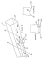
- FIG. 1 illustrates a urine sample collection device 1 based on the disclosure of this earlier patent application.
- the device has a urine receptor generally identified by reference numeral 2. This comprises a surface 7 which defines at one end an outlet aperture 3 and which flares out to define at its other end a rim 8 forming a perimeter of an inlet area into which a user urinates.
- the various forms of the receptor are described in more detail in the aforementioned patent application.
- the outlet aperture is coupled to one end of a generally elongate hollow tubular member or pipe portion 4. The other end of the tubular member is open.
- the tubular member 4 narrows along its length and the end remote from the outlet aperture 3 defines a generally oblong excess outlet aperture 6.
- a sample container coupling 5 comprises a short hollow stub like tube which is formed with a passage therethrough which meets an opening in the centre of the side of the tubular member.
- the sample container coupling 5 is located along the tubular member 4 to be spaced from the outlet aperture 3.
- the sample container coupling is formed to provide a push fit for a standard urine sample collection container or bottle (not shown).
- the sample container coupling 5 is located and formed such that the sample container is orientated vertically downwards during use.
- a standard tubular urine sample collection container (not shown) is pushed onto the sample container coupling 5.
- a female user locates the receptor 2 against their body to cover the urethra as explained more fully in the aforementioned patent application.
- a male user locates the end of their penis into the receptor.
- a known such device is disclosed in WO 1990/013280 .
- This document describes a urine sample collection device in which a user urinates into a funnel shaped urine receptor connected to an elongate tubular member extending to an open end.
- An opening in the side of the tubular member is connected to a urine collection container by a manually operated air-lock system to control whether urine will flow into the container.
- a lug portion is provided opposite the opening to deflect a portion of urine flowing through the tubular member into the container when the valve has been opened.
- the urine flows through the device and out of the excess outlet aperture with a proportion of that urine flow being collected in the collection container via sample container coupling 5.
- This through flow type of device differs from devices where all the urine flow is directed straight into a collection container.
- MSU mid stream urine
- Another urine sample collection device is known from US 4 494 581 . This device collects the initial urine void stream in a tube containing pellets which swell until a member closes the inflow opening of the tube after which a urine sample is collected.
- a urine sample collection device comprising:-
- the flow director directs urine which is not from the midstream towards the open end of the tubular member and directs midstream urine into the urine collection container.
- flared out we mean any shape which changes from a narrow shape to a broad shape.
- the flow director comprises a projection towards a longitudinal axis of the tubular member.
- the projection is provided upstream of the opening. This projection can be used to divert the flow of the urine away from the opening.
- the projection is also formed downstream of the opening.
- the projection upstream of the opening has a surface inclined relative to the surface of said side of the tubular member.
- the projection upstream of the opening comprises a wall which extends across the tubular member to an extent corresponding to the upstream edge of said opening.
- the flow director is formed to channel the urine flow along either side of the aperture.
- the projection towards the longitudinal axis of the tubular member comprises the passage of the coupling means, the passage extending into the tubular member and presenting an area within the tubular member into which urine can enter and flow into the collection container.
- the area does not have to be in the same plane as the walls of the elongate tubular member.
- the passage of the coupling means extends into the tubular member by an amount corresponding to between 20 and 60% of the height of the internal dimension of the tubular member.
- the area conveniently comprises a semi-circle, and wherein the passage extends into the tubular member to a greater extent downstream than upstream.
- the coupling means preferably includes a further passage extending therethrough which meets said opening to present an area from which air in the collection container can escape into the tubular member.
- the further passage of the coupling means preferably extends into the tubular member by an amount which is greater than the urine passage.
- the further (air) passage can be upstream or downstream of the urine passage. It should be noted that by designating the passages air and urine it does not preclude other fluids or a mixture thereof flowing through the passages (e.g air can flow through the urine passage).
- an opening of the further passage in the tubular member faces downstream.
- the opening in the further passage is at an incline facing downstream relative to the surface of said side of the tubular member.
- a covering means for the opening is provided adjacent the opening in the further passage.
- the body has evolved such that urine travelling out of the body travels in a spiral configuration in order to reduce the amount spraying. As the urine travels down the elongate tubular member in a spiral configuration it can cause an air lock in the further passage. As will be appreciated, the air lock stops the urine flowing into the urine collection container. If the opening of the passage faces downstream, is at an incline or there is a cover provided to deflect the urine away from the opening then the likelihood of an air lock being produced is reduced.
- tubular member tapers to said open end. Accordingly, the urine which is flowing through the tubular member and past the opening in the side thereof will begin to "back-up" when sufficient urine is flowing (i.e during the midstream) and, therefore, will start to flow through the opening in the side of the tubular member and into the urine collection container.
- the device further comprises a flow limiter, or urine collection container having a flow limiter, for limiting flow of urine into the container.
- the flow limiter preferably allows urine to enter a container to a predetermined limit, after which further urine is prevented from entering the container. In this way, the amount of urine entering the container cannot exceed a predetermined maximum, for example beyond a fraction (e.g. from 50 to 75%) of the capacity of the container.
- the flow limiter may limit flow of urine into the container by preventing ingress of urine, or by preventing egress of displaced air from the container.
- the flow limiter may prevent ingress of urine into the container by means of a valve between the opening and a container in use, which valve closes when the urine in the container reaches a predetermined level.
- the device may comprise a passage, for example between the container and the tubular member, through which air displaced from the container by ingress of urine can escape from the container, whereby urine is prevented from entering the container by the urine level rising to cover the container-side opening of the passage. In this way, further urine is prevented from entering the container by preventing air from being displaced from the container.
- the urine and air passages extend into the container, which is fitted to the device such that substantially all fluid transfer between the tubular member and the container occurs via the said passages, in particular transfer of urine from the tubular member to the container via the urine passage and transfer of air from the container to the tubular member via the air passage.
- air is displaced into the tubular member via the air passage.
- the level of urine in the container rises to cover the container-side opening of the air passage, no further air can be displaced from the container into the tubular member, and hence no further urine can enter the container.
- the amount of urine which can enter the container is thus largely determined in this embodiment by the extent to which the second passage extends into the container.
- the flow limiter comprises a valve through which urine can flow from the tubular member into a container.
- the valve may comprise a lower opening through which urine can pass into the container, an upper opening through which urine can enter the valve from the tubular member, and a closure member positioned between the upper and lower openings, and dimensioned so as to be capable of closing the upper opening.
- the closure member may conveniently have a density lower than that of urine, i.e. it will float in urine, so that as the level of urine in the container rises to reach the closure member it will float upon the urine.
- the closure member will rise with the urine, until it reaches the upper opening to form a seal therewith, thus preventing further urine from entering the container.
- Figure 2 illustrates an oblique perspective view of a portion of a tubular member 4' corresponding to the tubular member 4 shown in figure 1 .
- the tubular member has a generally square cross section as shown in the drawings but is not limited thereto.
- the tubular member has a base 20 from which a sample container coupling 5' extends.
- the sample container coupling 5' has a passage therethrough which meets an opening formed in the base of the tubular member 4', the opening defining a planar area 21.
- urine flowing down the tubular member 4' can pass down into a collection container (not shown) fitted to the coupling 5'.
- the flow of urine in the tubular member 4' is indicated by an arrow U, substantially along the axis of the tubular member.
- the base 20A which is upstream of the area 21 is formed to include an inclined surface or ramp 24 which leads up to the area 21.
- the ramp therefore projects towards the axis of the tubular member.
- the area 21 is substantially parallel to the surface of upstream base 20A but is not in the same plane.
- the central member of the base of the tubular member 4' along the axis thereof defines a plateau surface 22 which is on the plane defined by the area 21.
- channels 23 are formed which extend either side of the area 21 to meet the base 20 which is upstream of the area 21.
- the base of the channels 23 is on the plane of the base 20 which is upstream of the area 21.
- the volume of urine entering the tubular member 4' will eventually be greater than that leaving through the aperture 6.
- a front of fluid begins to "back up” along the tubular member.
- the collection container will begin to fill.
- the early part of the urine flow does not pass into the collection container so that an MSU sample is collected.
- the present invention is capable of considerable modification, the detailed embodiments of which will be readily apparent to those skilled in the art.
- the present embodiment has been described to include channels 23, these can be omitted such that the ramp 24 extends across the width of the base 20 if very slow urine flow is not to be considered a problem during urine collection.
- the angle and size of ramp can be varied.
- a ramp has been described as the flow director, a wall can be used which extends across the base 24 to an extent corresponding to the upstream edge of the area 21 such that the area is masked from the direct flow of urine along the tubular member 4'.
- the wall can also be V-shaped pointing upstream so that slow moving urine is directed around the area 21.
- the coupling 5' can be made such that it extends through the base 20 whereby its upper edge defines the area 21 which is in a plane located displaced relative to the base 20.
- the urine receptor 2 " is substantially identical to that shown in figures 1 to 4 .
- the device has a tubular member 4'' which comprises a constant circular cross-section tube, that is to say, it does not narrow between the urine receptor 2" and the excess outlet aperture 6".
- a sample container coupling 5" is located as with figures 1 to 4 .
- the outer surface of the coupling 5" has a portion 10 at the end onto which a sample container can be attached, this portion having a circular cross-section outer surface.
- the outer surface of the coupling 5" also has a portion 12 where the coupling meets the tubular member 4" .
- the portion 12 has a larger circumference than the portion 10, the portions 10 and 12 meeting at an elbow 11.
- a passage is formed through the coupling 5 " which comprises a circular cross-section tube which is split into first and second separate channels 13 and 14 having respective semi-circular cross-sections, as can be seen from figure 6 .
- One end (the lower end) of the channels 13 and 14 extend equally from the lower edge of the portion 10, as can be seen from figure 7 .
- the other end (the upper end) of the channels 13 and 14 extend through the base of and into the tubular member 4" .
- the upper edge of the channel 14 extends further into the tubular member 4 " than the channel 13 and is located on the side towards the outlet aperture 6" (downstream).
- the upper edge of the channel 13 defines a semi-circular area 21" whilst the upper edge of the channel 14 defines a semi-circular area 15.
- the upper edge 15 has a height from the base of the tubular member 4" which is greater than "a” so that urine does not normally flow down channel 14.
- the height "a” is preferably in the range of 20 to 60% of the height of the tubular member 4" at the point of the coupling 5''.
- the area 21" is effectively spaced from the base or lower surface of the tubular member 4 " by an a distance which provides a wall against slow flowing urine.
- the present invention may be produced from a plastics material injected into a tool having a shaped insert to form the tubular member 4'.
- the tubular insert can be a single piece that is withdrawn in the direction of the receptor 2. If a two piece insert is used, it is possible to have the area 21 made such that it is in the plane of the base 20 but the top edge of the ramp 24 remains displaced from the plane of the base.
- a flow limiter for use with the urine collection devices illustrated in the previous Figures comprises a valve 100 for preventing ingress of urine into a container 122.
- the valve 100 is positioned within the first channel 13, described with reference to Figures 5 to 7 , with corresponding second channel 14 for escape of displaced air into the tubular member (not shown in Figure 8 ).
- the valve 100 comprises an upper opening 102, a lower opening 104 and a closure member in the form of a ball 106.
- the ball 106 has an overall density lower than that of urine, and will thus float on urine, and is initially maintained in position away from the lower opening 104 by an internal wall 108 so as not to block the lower opening 104.
- the diameter of the ball 106 is greater than that of the upper opening 102.
- urine will enter the valve 100 from the tubular member as indicated by arrow A, passing through and out of the valve 100 as indicated by arrow A' into the container 122.
- the urine level in the container 122 will rise, and after a time will enter the valve 100 via lower opening 104.
- the ball 106 will float on the urine, until it reaches the upper opening 102, i.e. urine will rise within the container 122 to the level approximately indicated by arrows B in Figure 8 .
- the ball 106 will then close the upper opening 102, thus preventing further urine from entering the valve 100, and hence the container 122.
- a further flow limiter which comprises first and second channels 13 and 14, described with reference to Figures 5 to 7 .
- the second channel 14 extends into the container 122 by an amount which is greater than the first channel 13.
- the container 122 forms a fluid tight seal with the coupling 105, i.e. urine can enter the container 122 only through first channel 13 and displaced air can only escape from the container 122 through second channel 14.
- urine passes into the container 122 from the tubular member (not shown in Figure 9 ) via channel 13, as indicated by arrow A", and displaced air passes out of the container 122 via channel 14, as indicated by arrow C.
- FIG. 10 A further flow limiter for use with the urine sample collection devices shown in Figures 1 to 7 is illustrated in Figure 10 .
- This flow limiter is substantially identical to that shown in Figure 9 with the exception that the coupling 115 is hollow, and the first and second channels 13 and 14 respectively passing therethrough are contiguous.
Landscapes
- Health & Medical Sciences (AREA)
- Life Sciences & Earth Sciences (AREA)
- General Health & Medical Sciences (AREA)
- Animal Behavior & Ethology (AREA)
- Engineering & Computer Science (AREA)
- Biomedical Technology (AREA)
- Heart & Thoracic Surgery (AREA)
- Veterinary Medicine (AREA)
- Public Health (AREA)
- Vascular Medicine (AREA)
- Epidemiology (AREA)
- Nursing (AREA)
- Orthopedic Medicine & Surgery (AREA)
- Pathology (AREA)
- Medical Informatics (AREA)
- Molecular Biology (AREA)
- Surgery (AREA)
- Hematology (AREA)
- Investigating Or Analysing Biological Materials (AREA)
- Sampling And Sample Adjustment (AREA)
- Orthopedics, Nursing, And Contraception (AREA)
Claims (22)
- Urinproben-Sammelvorrichtung, die Folgendes aufweist:einen Urin-Empfänger (2, 2") mit einer Oberfläche (7), die von einer Auslassöffnung (3) zu einem Rand (8), der eine äußere Umgrenzungslinie eines Einlassbereichs definiert, in das ein Anwender uriniert, breiter wird;ein allgemein längliches rohrförmiges Element (4, 4', 4"), das sich von der Empfänger-Auslassöffnung (3) zu einem offenen Ende (6, 6") erstreckt und urinierten Urin empfängt, der von der Auslassöffnung fließt, wobei das rohrförmige Element eine Öffnung (21, 21") in seiner Seite ausgebildet hat;eine Kopplungseinrichtung (5, 5') zum lösbaren Anbringen eines Urin-Sammelbehälters;wobei die Kopplungseinrichtung einen sich durch sie erstreckenden Durchgang hat, der die Öffnung trifft, wodurch im rohrförmigen Element fließender Urin von da in einen angebrachten Behälter fließen kann; gekennzeichnetdurch ein Fluss-Richtgerät (22, 23, 24, 13, 14), das innerhalb des rohrförmigen Elements bei oder benachbart zu der Öffnung angeordnet ist und ausgebildet ist, um Urin hinter die Öffnung zu richten.
- Vorrichtung nach Anspruch 1, wobei das Fluss-Richtgerät einen Vorsprung (13, 14) in Richtung zu einer Längsachse des rohrförmigen Elements aufweist.
- Vorrichtung nach Anspruch 2, wobei der Vorsprung stromaufwärts von der Öffnung vorgesehen ist.
- Vorrichtung nach Anspruch 3, wobei der Vorsprung auch stromabwärts von der Öffnung vorgesehen ist.
- Vorrichtung nach Anspruch 3 oder 4, wobei der Vorsprung stromaufwärts von der Öffnung eine Oberfläche (24) hat, die bezüglich der Oberfläche der Seite des rohrförmigen Elements geneigt ist.
- Vorrichtung nach Anspruch 3 oder 4, wobei der Vorsprung stromaufwärts von der Öffnung eine Wand aufweist, die sich bis zu einem Ausmaß entsprechend einem stromaufwärtigen äußersten Rand der Öffnung quer über das rohrförmige Element erstreckt.
- Vorrichtung nach einem der vorangehenden Ansprüche, wobei das Fluss-Richtgerät ausgebildet ist, um den Urinfluss entlang jeder Seite der Öffnung zu kanalisieren.
- Vorrichtung nach Anspruch 2, wobei der Vorsprung in Richtung zu der Längsachse des rohrförmigen Elements den Durchgang der Kopplungseinrichtung aufweist, wobei sich der Durchgang in das rohrförmige Element erstreckt und einen Bereich innerhalb des rohrförmigen Elements präsentiert, in den Urin eintreten und in den Sammelbehälter fließen kann.
- Vorrichtung nach Anspruch 8, wobei sich der Durchgang der Kopplungseinrichtung in das rohrförmige Element für ein Ausmaß (a) entsprechend zwischen 20 und 60% der Höhe der Innenabmessung des rohrförmigen Elements erstreckt.
- Vorrichtung nach Anspruch 8 oder 9, wobei der Bereich (21") einen Halbkreis aufweist und wobei sich der Durchgang in das rohrförmige Element stromabwärts zu einem größeren Ausmaß als stromaufwärts erstreckt.
- Vorrichtung nach einem der Ansprüche 8 bis 10, wobei die Kopplungseinrichtung einen weiteren sich durch sie erstreckenden Durchgang (14) enthält, der die Öffnung trifft, um einen Bereich zu präsentieren, aus dem Luft im Sammelbehälter in das rohrförmige Element entweichen kann.
- Vorrichtung nach Anspruch 11, wobei sich der weitere Durchgang der Kopplungseinrichtung in das rohrförmige Element für ein Ausmaß erstreckt, das größer als bei dem zuerst angegebenen Durchgang ist.
- Vorrichtung nach Anspruch 11 oder 12, wobei eine Öffnung des weiteren Durchgangs im rohrförmigen Element stromabwärts liegt.
- Vorrichtung nach einem der Ansprüche 11 bis 13, wobei die Öffnung im weiteren Durchgang bei einer bezüglich der Oberfläche der Seite des rohrförmigen Elements stromabwärts liegenden Neigung ist.
- Vorrichtung nach einem der Ansprüche 11 bis 14, wobei eine Abdeckeinrichtung für die Öffnung benachbart zur Öffnung vorgesehen ist.
- Vorrichtung nach einem der vorangehenden Ansprüche, wobei sich das rohrförmige Element zum offenen Ende verjüngt.
- Vorrichtung nach einem der vorangehenden Ansprüche, die weiterhin einen Flussbegrenzer oder einen Urin-Sammelbehälter mit einem Flussbegrenzer zum Begrenzen eines Flusses von Urin in den Behälter aufweist.
- Vorrichtung nach Anspruch 17, wobei der Flussbegrenzer zulässt, dass Urin bis zu einer vorbestimmten Grenze in den Behälter eintritt, wonach verhindert wird, dass weiterer Urin in den Behälter eintritt.
- Vorrichtung nach Anspruch 17 oder 18, wobei der Flussbegrenzer ein Ventil (100) zwischen der Öffnung und einem im Einsatz befindlichen Behälter aufweist, welches Ventil sich schließt, wenn der Urin im Behälter einen vorbestimmten Pegel erreicht.
- Vorrichtung nach einem der Ansprüche 17 bis 19, wobei der Flussbegrenzer ein Ventil aufweist, durch welches Urin vom rohrförmigen Element in einen Behälter fließen kann, wobei das Ventil eine untere Öffnung (104) aufweist, durch welche Urin in den Behälter laufen kann, eine obere Öffnung (102), durch welche Urin vom rohrförmigen Element in das Ventil eintreten kann, und ein Schließelement (106), das zwischen der oberen und der unteren Öffnung positioniert ist und derart dimensioniert ist, dass es die obere Öffnung schließen kann.
- Vorrichtung nach Anspruch 20, wobei das Schließelement eine Dichte hat, die niedriger als diejenige von Urin ist.
- Vorrichtung nach Anspruch 20 oder 21, wobei das Schließelement eine Kugel aufweist.
Applications Claiming Priority (7)
| Application Number | Priority Date | Filing Date | Title |
|---|---|---|---|
| GB0203993A GB0203993D0 (en) | 2002-02-20 | 2002-02-20 | Improvements relating to a urine sample collection device |
| GB0203993 | 2002-02-20 | ||
| GB0208895 | 2002-04-18 | ||
| GB0208895A GB0208895D0 (en) | 2002-04-18 | 2002-04-18 | Improvements relating to a urine sample collection device |
| GB0213601 | 2002-06-13 | ||
| GB0213601A GB0213601D0 (en) | 2002-06-13 | 2002-06-13 | A urine sample collection device |
| PCT/GB2003/000472 WO2003070131A1 (en) | 2002-02-20 | 2003-02-04 | A urine sample collection device |
Publications (2)
| Publication Number | Publication Date |
|---|---|
| EP1476101A1 EP1476101A1 (de) | 2004-11-17 |
| EP1476101B1 true EP1476101B1 (de) | 2008-03-19 |
Family
ID=27256380
Family Applications (1)
| Application Number | Title | Priority Date | Filing Date |
|---|---|---|---|
| EP03704758A Expired - Lifetime EP1476101B1 (de) | 2002-02-20 | 2003-02-04 | Behälter zur aufnahme von urinproben |
Country Status (15)
| Country | Link |
|---|---|
| US (2) | US20050177070A1 (de) |
| EP (1) | EP1476101B1 (de) |
| JP (1) | JP2005517939A (de) |
| KR (1) | KR20040104459A (de) |
| CN (1) | CN1311792C (de) |
| AT (1) | ATE389377T1 (de) |
| AU (1) | AU2003207018B2 (de) |
| CA (1) | CA2508550A1 (de) |
| DE (1) | DE60319808T2 (de) |
| ES (1) | ES2303890T3 (de) |
| GB (1) | GB2385532B (de) |
| IL (1) | IL163570A0 (de) |
| MX (1) | MXPA04008095A (de) |
| PL (1) | PL371091A1 (de) |
| WO (1) | WO2003070131A1 (de) |
Families Citing this family (100)
| Publication number | Priority date | Publication date | Assignee | Title |
|---|---|---|---|---|
| GB0410142D0 (en) * | 2004-05-07 | 2004-06-09 | Cunningham Robert W | Urine collection device |
| TR201900083T4 (tr) * | 2006-06-30 | 2019-02-21 | Kyungin Metal Ind Co Ltd | İnsan idrarının toplanmasına ve analizine yönelik aparat. |
| GB2440842B (en) | 2006-09-30 | 2008-08-20 | Funnelly Enough Ltd | Urine collection device |
| US8043230B2 (en) * | 2007-01-20 | 2011-10-25 | Glynis Deadwyler | Urine specimen collection device |
| US8016779B2 (en) | 2007-04-09 | 2011-09-13 | Tyco Healthcare Group Lp | Compression device having cooling capability |
| US8034007B2 (en) | 2007-04-09 | 2011-10-11 | Tyco Healthcare Group Lp | Compression device with structural support features |
| US8128584B2 (en) | 2007-04-09 | 2012-03-06 | Tyco Healthcare Group Lp | Compression device with S-shaped bladder |
| US8162861B2 (en) | 2007-04-09 | 2012-04-24 | Tyco Healthcare Group Lp | Compression device with strategic weld construction |
| US8070699B2 (en) | 2007-04-09 | 2011-12-06 | Tyco Healthcare Group Lp | Method of making compression sleeve with structural support features |
| US8109892B2 (en) | 2007-04-09 | 2012-02-07 | Tyco Healthcare Group Lp | Methods of making compression device with improved evaporation |
| US7903604B2 (en) * | 2007-04-18 | 2011-03-08 | Wi-Lan Inc. | Method and apparatus for a scheduler for a macro-diversity portion of a transmission |
| US7762596B1 (en) | 2008-02-25 | 2010-07-27 | Gaydos Kelly M | Urine sample retrieval device |
| US8114117B2 (en) | 2008-09-30 | 2012-02-14 | Tyco Healthcare Group Lp | Compression device with wear area |
| GB0821057D0 (en) * | 2008-11-18 | 2008-12-24 | Knight Scient Ltd | Device for collecting first pass urine |
| NL1039286C2 (en) | 2012-01-06 | 2013-07-25 | Astrid Madsy Senus | Portable non-invasive urinary aids for women. |
| US9205021B2 (en) | 2012-06-18 | 2015-12-08 | Covidien Lp | Compression system with vent cooling feature |
| GB201303799D0 (en) | 2013-03-04 | 2013-04-17 | Forte Medical Ltd | Urine collection device |
| US9155525B2 (en) | 2013-03-15 | 2015-10-13 | Lipinsky Enterprises, LLC | Urine sample collection device |
| GB2520970B (en) * | 2013-12-05 | 2015-11-11 | P1 Technology Ltd | Collecting a urine sample |
| US10390989B2 (en) | 2014-03-19 | 2019-08-27 | Purewick Corporation | Apparatus and methods for receiving discharged urine |
| US11806266B2 (en) | 2014-03-19 | 2023-11-07 | Purewick Corporation | Apparatus and methods for receiving discharged urine |
| US11376152B2 (en) | 2014-03-19 | 2022-07-05 | Purewick Corporation | Apparatus and methods for receiving discharged urine |
| US10226376B2 (en) | 2014-03-19 | 2019-03-12 | Purewick Corporation | Apparatus and methods for receiving discharged urine |
| US10952889B2 (en) | 2016-06-02 | 2021-03-23 | Purewick Corporation | Using wicking material to collect liquid for transport |
| US11090183B2 (en) | 2014-11-25 | 2021-08-17 | Purewick Corporation | Container for collecting liquid for transport |
| US9931102B1 (en) | 2014-07-08 | 2018-04-03 | Kimberly A. Studer | Specimen collection system for use with urinal |
| WO2017023794A1 (en) * | 2015-07-31 | 2017-02-09 | Medivance Incorporated | Urine output collection and monitoring system |
| KR101732843B1 (ko) | 2015-11-06 | 2017-05-24 | 가톨릭대학교 산학협력단 | 소변의 분리 및 감염 관리를 위한 진보된 소변 검사용 용기 |
| WO2017078493A1 (ko) * | 2015-11-06 | 2017-05-11 | 가톨릭대학교 산학협력단 | 소변의 분리 및 감염 관리를 위한 진보된 소변 검사용 용기 |
| USD928946S1 (en) | 2016-06-02 | 2021-08-24 | Purewick Corporation | Urine receiving apparatus |
| US10973678B2 (en) | 2016-07-27 | 2021-04-13 | Purewick Corporation | Apparatus and methods for receiving discharged urine |
| US10376407B2 (en) | 2016-08-16 | 2019-08-13 | Purewick Corporation | Using wicking material to collect urine from a male for transport |
| US10376406B2 (en) | 2016-07-27 | 2019-08-13 | Purewick Corporation | Male urine collection device using wicking material |
| CN110612075B (zh) | 2017-01-31 | 2022-09-09 | 普利维克公司 | 用于接收排出的尿液的装置和方法 |
| WO2019212949A1 (en) | 2018-05-01 | 2019-11-07 | Purewick Corporation | Fluid collection devices, systems, and methods |
| CA3098680A1 (en) | 2018-05-01 | 2019-11-07 | Purewick Corporation | Fluid collection garments |
| EP3787569B1 (de) | 2018-05-01 | 2025-07-16 | Purewick Corporation | Flüssigkeitssammelvorrichtungen und -systeme |
| CN112367949B (zh) | 2018-05-01 | 2023-09-12 | 普利维克公司 | 流体收集装置、相关系统及相关方法 |
| KR102492111B1 (ko) | 2018-05-01 | 2023-01-27 | 퓨어윅 코포레이션 | 유체 수집 장치 및 이를 사용하는 방법 |
| KR102493455B1 (ko) | 2018-05-01 | 2023-01-31 | 퓨어윅 코포레이션 | 유체 수집 장치, 관련 시스템 및 관련 방법 |
| EP3784322B1 (de) | 2018-05-22 | 2023-11-22 | C. R. Bard, Inc. | Katheterisierungssystem und anwendungsverfahren dafür |
| EP3833257B1 (de) | 2018-08-10 | 2025-09-24 | C. R. Bard, Inc. | Automatisierte urinproduktionsmesssysteme und verfahren dafür |
| USD929578S1 (en) | 2019-06-06 | 2021-08-31 | Purewick Corporation | Urine collection assembly |
| WO2020256865A1 (en) | 2019-06-21 | 2020-12-24 | Purewick Corporation | Fluid collection devices including a base securement area, and related systems and methods |
| CN114375187A (zh) | 2019-07-11 | 2022-04-19 | 普奥维克有限公司 | 流体收集装置、系统和方法 |
| EP3999003B1 (de) | 2019-07-19 | 2024-05-01 | Purewick Corporation | Fluidsammelvorrichtungen mit mindestens einem formgedächtnismaterial |
| US12290366B2 (en) * | 2019-10-24 | 2025-05-06 | The Regents Of The University Of Michigan | Uroflowmetry systems having wearable uroflowmeters, and methods of operating the same |
| CN114867435B (zh) | 2019-10-28 | 2025-12-23 | 普利维克公司 | 包括样本端口的流体收集组件 |
| EP4084746B1 (de) | 2020-01-03 | 2025-04-02 | Purewick Corporation | Urinsammelvorrichtungen mit einem relativ breiten abschnitt und einem länglichen teil und zugehörige verfahren |
| US11950769B2 (en) | 2020-01-31 | 2024-04-09 | Arizona Board Of Regents On Behalf Of Arizona State University | Urine collection, storage, and testing assembly |
| US12589022B2 (en) | 2020-03-19 | 2026-03-31 | Purewick Corporation | Fluid collection assemblies including one or more movement enhancing features |
| US12521288B2 (en) | 2020-03-26 | 2026-01-13 | Purewick Corporation | Multi-layer urine capture device and related methods |
| EP4344685B1 (de) | 2020-04-10 | 2025-06-11 | Purewick Corporation | Flüssigkeitssammelanordnungen mit einer oder mehreren leckverhinderungsmerkmalen |
| US12447042B2 (en) | 2020-04-17 | 2025-10-21 | Purewick Corporation | Fluid collection assemblies including a fluid impermeable barrier having a sump and a base |
| WO2021211729A1 (en) | 2020-04-17 | 2021-10-21 | Purewick Corporation | Fluid collection devices, systems, and methods securing a protruding portion in position for use |
| WO2021211599A1 (en) | 2020-04-17 | 2021-10-21 | Purewick Corporation | Female external catheter devices having a urethral cup, and related systems and methods |
| WO2021216422A1 (en) | 2020-04-20 | 2021-10-28 | Purewick Corporation | Fluid collection devices adjustable between a vacuum- based orientation and a gravity-based orientation, and related systems and methods |
| US12048643B2 (en) | 2020-05-27 | 2024-07-30 | Purewick Corporation | Fluid collection assemblies including at least one inflation device and methods and systems of using the same |
| US12083261B2 (en) | 2020-06-05 | 2024-09-10 | C. R. Bard, Inc. | Automated fluid output monitoring |
| US11703365B2 (en) | 2020-07-14 | 2023-07-18 | C. R. Bard, Inc. | Automatic fluid flow system with push-button connection |
| USD967409S1 (en) | 2020-07-15 | 2022-10-18 | Purewick Corporation | Urine collection apparatus cover |
| US12055249B2 (en) | 2020-07-21 | 2024-08-06 | C. R. Bard, Inc. | Automatic fluid flow system with retractable connection |
| WO2022031943A1 (en) | 2020-08-06 | 2022-02-10 | Purewick Corporation | A fluid collection system including a garment and a fluid collection device |
| US20220047410A1 (en) | 2020-08-11 | 2022-02-17 | Purewick Corporation | Fluid collection assemblies defining waist and leg openings |
| US12521272B2 (en) | 2020-09-09 | 2026-01-13 | Purewick Corporation | Fluid collection devices, systems, and methods |
| US11801186B2 (en) | 2020-09-10 | 2023-10-31 | Purewick Corporation | Urine storage container handle and lid accessories |
| US12156792B2 (en) | 2020-09-10 | 2024-12-03 | Purewick Corporation | Fluid collection assemblies including at least one inflation device |
| US12042423B2 (en) | 2020-10-07 | 2024-07-23 | Purewick Corporation | Fluid collection systems including at least one tensioning element |
| US12208031B2 (en) | 2020-10-21 | 2025-01-28 | Purewick Corporation | Adapters for fluid collection devices |
| US12257174B2 (en) | 2020-10-21 | 2025-03-25 | Purewick Corporation | Fluid collection assemblies including at least one of a protrusion or at least one expandable material |
| US12569365B2 (en) | 2020-10-21 | 2026-03-10 | Purewick Corporation | Fluid collection assemblies including at least one shape memory material disposed in the conduit |
| US12440370B2 (en) | 2020-10-21 | 2025-10-14 | Purewick Corporation | Apparatus with compressible casing for receiving discharged urine |
| US12048644B2 (en) | 2020-11-03 | 2024-07-30 | Purewick Corporation | Apparatus for receiving discharged urine |
| US12070432B2 (en) | 2020-11-11 | 2024-08-27 | Purewick Corporation | Urine collection system including a flow meter and related methods |
| US12245967B2 (en) | 2020-11-18 | 2025-03-11 | Purewick Corporation | Fluid collection assemblies including an adjustable spine |
| US12558474B2 (en) | 2020-11-19 | 2026-02-24 | C. R. Bard, Inc. | Dynamic pressure response system |
| US12408853B2 (en) | 2020-12-17 | 2025-09-09 | C. R. Bard, Inc. | Smart bag to measure urine output via catheter |
| US12364423B2 (en) | 2020-12-21 | 2025-07-22 | C. R. Bard, Inc. | Automated urinary output-measuring systems and methods |
| US11931151B2 (en) | 2020-12-22 | 2024-03-19 | C. R. Bard, Inc. | Automated urinary output measuring system |
| US12246146B2 (en) | 2020-12-23 | 2025-03-11 | C. R. Bard, Inc. | Automated weight based fluid output monitoring system |
| US12599495B2 (en) | 2021-01-05 | 2026-04-14 | Purewick Corporation | Male external catheter with attachment interface configured to bias against penis |
| US12268627B2 (en) | 2021-01-06 | 2025-04-08 | Purewick Corporation | Fluid collection assemblies including at least one securement body |
| JP2024503636A (ja) | 2021-01-07 | 2024-01-26 | ピュアウィック コーポレイション | 車椅子に固定可能な尿収集システムおよび関連する方法 |
| JP7500744B2 (ja) | 2021-01-19 | 2024-06-17 | ピュアウィック コーポレイション | 可変流体収集デバイス、システム、及び方法 |
| US12178735B2 (en) | 2021-02-09 | 2024-12-31 | Purewick Corporation | Noise reduction for a urine suction system |
| CN116615162A (zh) | 2021-02-26 | 2023-08-18 | 普奥维克有限公司 | 在管口与屏障之间具有储液槽的流体收集装置以及相关系统和方法 |
| US12558472B2 (en) | 2021-03-05 | 2026-02-24 | Purewick Corporation | Portable fluid collection systems with storage and related methods |
| US12551385B2 (en) | 2021-03-05 | 2026-02-17 | Purewick Corporation | Fluid collection assembly including a tube having porous wicking material for improved fluid transport |
| US11938054B2 (en) | 2021-03-10 | 2024-03-26 | Purewick Corporation | Bodily waste and fluid collection with sacral pad |
| US12458525B2 (en) | 2021-03-10 | 2025-11-04 | Purewick Corporation | Acoustic silencer for a urine suction system |
| US12029677B2 (en) | 2021-04-06 | 2024-07-09 | Purewick Corporation | Fluid collection devices having a collection bag, and related systems and methods |
| US12233003B2 (en) | 2021-04-29 | 2025-02-25 | Purewick Corporation | Fluid collection assemblies including at least one length adjusting feature |
| US12251333B2 (en) | 2021-05-21 | 2025-03-18 | Purewick Corporation | Fluid collection assemblies including at least one inflation device and methods and systems of using the same |
| US12324767B2 (en) | 2021-05-24 | 2025-06-10 | Purewick Corporation | Fluid collection assembly including a customizable external support and related methods |
| US12150885B2 (en) | 2021-05-26 | 2024-11-26 | Purewick Corporation | Fluid collection system including a cleaning system and methods |
| WO2023018475A2 (en) * | 2021-06-11 | 2023-02-16 | Triton Systems, Inc. | Bladder collection system |
| US12575960B2 (en) | 2021-06-24 | 2026-03-17 | Purewick Corporation | Urine collection systems having one or more of volume, pressure, or flow indicators, and related methods |
| US12551366B2 (en) | 2021-08-02 | 2026-02-17 | Purewick Corporation | Fluid collection devices having multiple fluid collection regions, and related systems and methods |
| US12446813B2 (en) | 2021-08-23 | 2025-10-21 | C. R. Bard, Inc. | Automated urine output system for attachment to hospital bed |
| US12594062B2 (en) | 2021-09-08 | 2026-04-07 | Purewick Corporation | Fluid collection assemblies including an extension |
Family Cites Families (9)
| Publication number | Priority date | Publication date | Assignee | Title |
|---|---|---|---|---|
| US3161891A (en) * | 1963-12-12 | 1964-12-22 | Ralph M Bauman | Portable urine specimen collecting device |
| US3750647A (en) * | 1970-04-23 | 1973-08-07 | R Reilly | Means for collecting specimens of urine |
| US4252132A (en) * | 1978-10-10 | 1981-02-24 | Shs Enterprises, Ltd. | Midstream urine specimen collecting device |
| US4494581A (en) * | 1983-02-18 | 1985-01-22 | Whitman Medical Corporation | Isolation of forestream and midstream portions of collected urine samples |
| IE901497L (en) * | 1989-04-28 | 1990-10-28 | Max Planck Gesellschaft | Mid Stream Urine Device |
| EP0541091B1 (de) * | 1991-11-08 | 1997-01-29 | Sakai, Yoshisuke | Urinsammelvorrichtung |
| CN1118626A (zh) * | 1993-12-30 | 1996-03-13 | 东陶机器株式会社 | 尿的采样方法与采样装置 |
| US6254294B1 (en) * | 1999-08-09 | 2001-07-03 | Sigrid G. Muhar | Pharmaceutical kit |
| GB2362577B (en) * | 2000-03-30 | 2003-03-12 | Orde Levinson | Urine funnelling trumpet |
-
2003
- 2003-02-04 IL IL16357003A patent/IL163570A0/xx unknown
- 2003-02-04 AT AT03704758T patent/ATE389377T1/de not_active IP Right Cessation
- 2003-02-04 JP JP2003569092A patent/JP2005517939A/ja active Pending
- 2003-02-04 PL PL03371091A patent/PL371091A1/xx not_active Application Discontinuation
- 2003-02-04 ES ES03704758T patent/ES2303890T3/es not_active Expired - Lifetime
- 2003-02-04 WO PCT/GB2003/000472 patent/WO2003070131A1/en not_active Ceased
- 2003-02-04 EP EP03704758A patent/EP1476101B1/de not_active Expired - Lifetime
- 2003-02-04 DE DE60319808T patent/DE60319808T2/de not_active Expired - Lifetime
- 2003-02-04 CA CA002508550A patent/CA2508550A1/en not_active Abandoned
- 2003-02-04 MX MXPA04008095A patent/MXPA04008095A/es active IP Right Grant
- 2003-02-04 KR KR10-2004-7013003A patent/KR20040104459A/ko not_active Ceased
- 2003-02-04 CN CNB038040522A patent/CN1311792C/zh not_active Expired - Fee Related
- 2003-02-04 GB GB0302559A patent/GB2385532B/en not_active Expired - Fee Related
- 2003-02-04 AU AU2003207018A patent/AU2003207018B2/en not_active Expired - Fee Related
- 2003-02-04 US US10/505,232 patent/US20050177070A1/en not_active Abandoned
-
2009
- 2009-04-14 US US12/423,348 patent/US7871385B2/en not_active Expired - Fee Related
Also Published As
| Publication number | Publication date |
|---|---|
| IL163570A0 (en) | 2005-12-18 |
| ES2303890T3 (es) | 2008-09-01 |
| AU2003207018A1 (en) | 2003-09-09 |
| JP2005517939A (ja) | 2005-06-16 |
| US20090259205A1 (en) | 2009-10-15 |
| DE60319808D1 (de) | 2008-04-30 |
| AU2003207018B2 (en) | 2008-12-18 |
| WO2003070131A1 (en) | 2003-08-28 |
| DE60319808T2 (de) | 2009-04-16 |
| GB0302559D0 (en) | 2003-03-12 |
| MXPA04008095A (es) | 2004-11-26 |
| GB2385532B (en) | 2004-04-14 |
| GB2385532A (en) | 2003-08-27 |
| PL371091A1 (en) | 2005-06-13 |
| CN1311792C (zh) | 2007-04-25 |
| US7871385B2 (en) | 2011-01-18 |
| CA2508550A1 (en) | 2003-08-28 |
| CN1633267A (zh) | 2005-06-29 |
| KR20040104459A (ko) | 2004-12-10 |
| US20050177070A1 (en) | 2005-08-11 |
| ATE389377T1 (de) | 2008-04-15 |
| EP1476101A1 (de) | 2004-11-17 |
Similar Documents
| Publication | Publication Date | Title |
|---|---|---|
| EP1476101B1 (de) | Behälter zur aufnahme von urinproben | |
| US6163892A (en) | Portable male urinal | |
| US4276889A (en) | Urine specimen collecting device | |
| CA1087037A (en) | Peak flow measuring device | |
| KR20030009413A (ko) | 방뇨 장치 | |
| JP7669351B2 (ja) | 小容積液体サンプラー | |
| EP0731668B1 (de) | Gerät zur probeentnahme aus dem mittleren strom einer flüssigkeit | |
| ZA200407205B (en) | A urine sample collection device. | |
| CN205910035U (zh) | 自控阀尿液取样漏斗 | |
| CN209899441U (zh) | 一次性尿液采样器 | |
| WO1990013280A1 (en) | Mid stream urine device | |
| GB2098487A (en) | Device for collecting and holding urine | |
| CN107449640A (zh) | 液体分段收集器 | |
| CN221903774U (zh) | 一种便捷采尿检验装置 | |
| EP0243360A1 (de) | Vorrichtung zur entnahme von flüssigkeitsproben | |
| US20250345044A1 (en) | Liquid sampler for fast capture of initial volume of a liquid flow | |
| CN213551954U (zh) | 一种尿收集装置的连接件及其配合的集尿杯 | |
| CN108309362A (zh) | 一种多重防逆流尿液中段收集器 | |
| RU2004128468A (ru) | Устройство для сбора мочи | |
| CN205785959U (zh) | 避免划伤婴幼儿的防倒流小便标本杯 | |
| WO2006084405A1 (de) | Andockmundstück zur urinableitung bei der frau mit entsprechenden ergänzungs- und zusatzteilen | |
| WO1988000816A1 (en) | Valve for control of discharge from a stoma | |
| JPS5912057Y2 (ja) | 動物の実験用飼育装置における採尿装置 | |
| CN113288226A (zh) | 检验科用取尿装置 | |
| HU180229B (hu) | Berendezés vizeletminta szelektív gyűjtésére |
Legal Events
| Date | Code | Title | Description |
|---|---|---|---|
| PUAI | Public reference made under article 153(3) epc to a published international application that has entered the european phase |
Free format text: ORIGINAL CODE: 0009012 |
|
| 17P | Request for examination filed |
Effective date: 20040915 |
|
| AK | Designated contracting states |
Kind code of ref document: A1 Designated state(s): AT BE BG CH CY CZ DE DK EE ES FI FR GB GR HU IE IT LI LU MC NL PT SE SI SK TR |
|
| AX | Request for extension of the european patent |
Extension state: AL LT LV MK RO |
|
| REG | Reference to a national code |
Ref country code: HK Ref legal event code: DE Ref document number: 1070554 Country of ref document: HK |
|
| GRAP | Despatch of communication of intention to grant a patent |
Free format text: ORIGINAL CODE: EPIDOSNIGR1 |
|
| GRAS | Grant fee paid |
Free format text: ORIGINAL CODE: EPIDOSNIGR3 |
|
| GRAA | (expected) grant |
Free format text: ORIGINAL CODE: 0009210 |
|
| AK | Designated contracting states |
Kind code of ref document: B1 Designated state(s): AT BE BG CH CY CZ DE DK EE ES FI FR GB GR HU IE IT LI LU MC NL PT SE SI SK TR |
|
| REG | Reference to a national code |
Ref country code: GB Ref legal event code: FG4D |
|
| REG | Reference to a national code |
Ref country code: CH Ref legal event code: EP |
|
| REF | Corresponds to: |
Ref document number: 60319808 Country of ref document: DE Date of ref document: 20080430 Kind code of ref document: P |
|
| REG | Reference to a national code |
Ref country code: IE Ref legal event code: FG4D |
|
| REG | Reference to a national code |
Ref country code: SE Ref legal event code: TRGR |
|
| REG | Reference to a national code |
Ref country code: GR Ref legal event code: EP Ref document number: 20080401591 Country of ref document: GR |
|
| PG25 | Lapsed in a contracting state [announced via postgrant information from national office to epo] |
Ref country code: FI Free format text: LAPSE BECAUSE OF FAILURE TO SUBMIT A TRANSLATION OF THE DESCRIPTION OR TO PAY THE FEE WITHIN THE PRESCRIBED TIME-LIMIT Effective date: 20080319 |
|
| REG | Reference to a national code |
Ref country code: CH Ref legal event code: NV Representative=s name: R. A. EGLI & CO. PATENTANWAELTE |
|
| PG25 | Lapsed in a contracting state [announced via postgrant information from national office to epo] |
Ref country code: AT Free format text: LAPSE BECAUSE OF FAILURE TO SUBMIT A TRANSLATION OF THE DESCRIPTION OR TO PAY THE FEE WITHIN THE PRESCRIBED TIME-LIMIT Effective date: 20080319 |
|
| REG | Reference to a national code |
Ref country code: ES Ref legal event code: FG2A Ref document number: 2303890 Country of ref document: ES Kind code of ref document: T3 |
|
| PG25 | Lapsed in a contracting state [announced via postgrant information from national office to epo] |
Ref country code: SI Free format text: LAPSE BECAUSE OF FAILURE TO SUBMIT A TRANSLATION OF THE DESCRIPTION OR TO PAY THE FEE WITHIN THE PRESCRIBED TIME-LIMIT Effective date: 20080319 Ref country code: BE Free format text: LAPSE BECAUSE OF FAILURE TO SUBMIT A TRANSLATION OF THE DESCRIPTION OR TO PAY THE FEE WITHIN THE PRESCRIBED TIME-LIMIT Effective date: 20080319 |
|
| PG25 | Lapsed in a contracting state [announced via postgrant information from national office to epo] |
Ref country code: CZ Free format text: LAPSE BECAUSE OF FAILURE TO SUBMIT A TRANSLATION OF THE DESCRIPTION OR TO PAY THE FEE WITHIN THE PRESCRIBED TIME-LIMIT Effective date: 20080319 Ref country code: PT Free format text: LAPSE BECAUSE OF FAILURE TO SUBMIT A TRANSLATION OF THE DESCRIPTION OR TO PAY THE FEE WITHIN THE PRESCRIBED TIME-LIMIT Effective date: 20080826 Ref country code: SK Free format text: LAPSE BECAUSE OF FAILURE TO SUBMIT A TRANSLATION OF THE DESCRIPTION OR TO PAY THE FEE WITHIN THE PRESCRIBED TIME-LIMIT Effective date: 20080319 |
|
| ET | Fr: translation filed | ||
| REG | Reference to a national code |
Ref country code: GB Ref legal event code: 732E |
|
| PLBE | No opposition filed within time limit |
Free format text: ORIGINAL CODE: 0009261 |
|
| STAA | Information on the status of an ep patent application or granted ep patent |
Free format text: STATUS: NO OPPOSITION FILED WITHIN TIME LIMIT |
|
| PG25 | Lapsed in a contracting state [announced via postgrant information from national office to epo] |
Ref country code: DK Free format text: LAPSE BECAUSE OF FAILURE TO SUBMIT A TRANSLATION OF THE DESCRIPTION OR TO PAY THE FEE WITHIN THE PRESCRIBED TIME-LIMIT Effective date: 20080319 |
|
| 26N | No opposition filed |
Effective date: 20081222 |
|
| PG25 | Lapsed in a contracting state [announced via postgrant information from national office to epo] |
Ref country code: EE Free format text: LAPSE BECAUSE OF FAILURE TO SUBMIT A TRANSLATION OF THE DESCRIPTION OR TO PAY THE FEE WITHIN THE PRESCRIBED TIME-LIMIT Effective date: 20080319 Ref country code: BG Free format text: LAPSE BECAUSE OF FAILURE TO SUBMIT A TRANSLATION OF THE DESCRIPTION OR TO PAY THE FEE WITHIN THE PRESCRIBED TIME-LIMIT Effective date: 20080619 |
|
| PG25 | Lapsed in a contracting state [announced via postgrant information from national office to epo] |
Ref country code: CY Free format text: LAPSE BECAUSE OF FAILURE TO SUBMIT A TRANSLATION OF THE DESCRIPTION OR TO PAY THE FEE WITHIN THE PRESCRIBED TIME-LIMIT Effective date: 20080319 Ref country code: MC Free format text: LAPSE BECAUSE OF NON-PAYMENT OF DUE FEES Effective date: 20090228 |
|
| PGFP | Annual fee paid to national office [announced via postgrant information from national office to epo] |
Ref country code: CH Payment date: 20090821 Year of fee payment: 7 Ref country code: NL Payment date: 20090831 Year of fee payment: 7 |
|
| PG25 | Lapsed in a contracting state [announced via postgrant information from national office to epo] |
Ref country code: GR Free format text: LAPSE BECAUSE OF NON-PAYMENT OF DUE FEES Effective date: 20090902 |
|
| REG | Reference to a national code |
Ref country code: NL Ref legal event code: V1 Effective date: 20100901 |
|
| REG | Reference to a national code |
Ref country code: CH Ref legal event code: PL |
|
| PG25 | Lapsed in a contracting state [announced via postgrant information from national office to epo] |
Ref country code: LI Free format text: LAPSE BECAUSE OF NON-PAYMENT OF DUE FEES Effective date: 20100228 Ref country code: CH Free format text: LAPSE BECAUSE OF NON-PAYMENT OF DUE FEES Effective date: 20100228 |
|
| PG25 | Lapsed in a contracting state [announced via postgrant information from national office to epo] |
Ref country code: NL Free format text: LAPSE BECAUSE OF NON-PAYMENT OF DUE FEES Effective date: 20100901 |
|
| PG25 | Lapsed in a contracting state [announced via postgrant information from national office to epo] |
Ref country code: LU Free format text: LAPSE BECAUSE OF NON-PAYMENT OF DUE FEES Effective date: 20090204 |
|
| PG25 | Lapsed in a contracting state [announced via postgrant information from national office to epo] |
Ref country code: HU Free format text: LAPSE BECAUSE OF FAILURE TO SUBMIT A TRANSLATION OF THE DESCRIPTION OR TO PAY THE FEE WITHIN THE PRESCRIBED TIME-LIMIT Effective date: 20080920 |
|
| PG25 | Lapsed in a contracting state [announced via postgrant information from national office to epo] |
Ref country code: ES Free format text: LAPSE BECAUSE OF NON-PAYMENT OF DUE FEES Effective date: 20110328 |
|
| PGFP | Annual fee paid to national office [announced via postgrant information from national office to epo] |
Ref country code: ES Payment date: 20110301 Year of fee payment: 9 |
|
| PG25 | Lapsed in a contracting state [announced via postgrant information from national office to epo] |
Ref country code: TR Free format text: LAPSE BECAUSE OF FAILURE TO SUBMIT A TRANSLATION OF THE DESCRIPTION OR TO PAY THE FEE WITHIN THE PRESCRIBED TIME-LIMIT Effective date: 20080319 |
|
| REG | Reference to a national code |
Ref country code: HK Ref legal event code: WD Ref document number: 1070554 Country of ref document: HK |
|
| REG | Reference to a national code |
Ref country code: GB Ref legal event code: 732E Free format text: REGISTERED BETWEEN 20111006 AND 20111012 |
|
| PGFP | Annual fee paid to national office [announced via postgrant information from national office to epo] |
Ref country code: IE Payment date: 20120216 Year of fee payment: 10 |
|
| PGFP | Annual fee paid to national office [announced via postgrant information from national office to epo] |
Ref country code: IT Payment date: 20120224 Year of fee payment: 10 Ref country code: SE Payment date: 20120216 Year of fee payment: 10 |
|
| REG | Reference to a national code |
Ref country code: ES Ref legal event code: FD2A Effective date: 20130708 |
|
| PG25 | Lapsed in a contracting state [announced via postgrant information from national office to epo] |
Ref country code: ES Free format text: LAPSE BECAUSE OF NON-PAYMENT OF DUE FEES Effective date: 20120205 |
|
| PGFP | Annual fee paid to national office [announced via postgrant information from national office to epo] |
Ref country code: FR Payment date: 20130628 Year of fee payment: 11 |
|
| REG | Reference to a national code |
Ref country code: SE Ref legal event code: EUG |
|
| PG25 | Lapsed in a contracting state [announced via postgrant information from national office to epo] |
Ref country code: SE Free format text: LAPSE BECAUSE OF NON-PAYMENT OF DUE FEES Effective date: 20130205 |
|
| REG | Reference to a national code |
Ref country code: IE Ref legal event code: MM4A |
|
| PG25 | Lapsed in a contracting state [announced via postgrant information from national office to epo] |
Ref country code: IT Free format text: LAPSE BECAUSE OF NON-PAYMENT OF DUE FEES Effective date: 20130204 |
|
| PG25 | Lapsed in a contracting state [announced via postgrant information from national office to epo] |
Ref country code: IE Free format text: LAPSE BECAUSE OF NON-PAYMENT OF DUE FEES Effective date: 20130204 |
|
| PGFP | Annual fee paid to national office [announced via postgrant information from national office to epo] |
Ref country code: DE Payment date: 20140318 Year of fee payment: 12 |
|
| PGFP | Annual fee paid to national office [announced via postgrant information from national office to epo] |
Ref country code: GB Payment date: 20140227 Year of fee payment: 12 |
|
| REG | Reference to a national code |
Ref country code: FR Ref legal event code: ST Effective date: 20141031 |
|
| PG25 | Lapsed in a contracting state [announced via postgrant information from national office to epo] |
Ref country code: FR Free format text: LAPSE BECAUSE OF NON-PAYMENT OF DUE FEES Effective date: 20140228 |
|
| REG | Reference to a national code |
Ref country code: DE Ref legal event code: R119 Ref document number: 60319808 Country of ref document: DE |
|
| GBPC | Gb: european patent ceased through non-payment of renewal fee |
Effective date: 20150204 |
|
| PG25 | Lapsed in a contracting state [announced via postgrant information from national office to epo] |
Ref country code: GB Free format text: LAPSE BECAUSE OF NON-PAYMENT OF DUE FEES Effective date: 20150204 Ref country code: DE Free format text: LAPSE BECAUSE OF NON-PAYMENT OF DUE FEES Effective date: 20150901 |