EP1476357B1 - Procede et systeme de compensation de desequilibre dynamique - Google Patents
Procede et systeme de compensation de desequilibre dynamique Download PDFInfo
- Publication number
- EP1476357B1 EP1476357B1 EP03713604A EP03713604A EP1476357B1 EP 1476357 B1 EP1476357 B1 EP 1476357B1 EP 03713604 A EP03713604 A EP 03713604A EP 03713604 A EP03713604 A EP 03713604A EP 1476357 B1 EP1476357 B1 EP 1476357B1
- Authority
- EP
- European Patent Office
- Prior art keywords
- momentum
- axis
- rotation
- rotational assembly
- assembly
- Prior art date
- Legal status (The legal status is an assumption and is not a legal conclusion. Google has not performed a legal analysis and makes no representation as to the accuracy of the status listed.)
- Expired - Lifetime
Links
- 238000000034 method Methods 0.000 title claims description 8
- 238000009987 spinning Methods 0.000 claims description 13
- 230000000712 assembly Effects 0.000 description 10
- 238000000429 assembly Methods 0.000 description 10
- 238000013459 approach Methods 0.000 description 2
- 230000003068 static effect Effects 0.000 description 2
- 230000002411 adverse Effects 0.000 description 1
- 230000003190 augmentative effect Effects 0.000 description 1
- 238000010586 diagram Methods 0.000 description 1
- 230000001747 exhibiting effect Effects 0.000 description 1
- 230000000116 mitigating effect Effects 0.000 description 1
- 230000006641 stabilisation Effects 0.000 description 1
- 238000011105 stabilization Methods 0.000 description 1
Images

Classifications
-
- B—PERFORMING OPERATIONS; TRANSPORTING
- B64—AIRCRAFT; AVIATION; COSMONAUTICS
- B64G—COSMONAUTICS; VEHICLES OR EQUIPMENT THEREFOR
- B64G1/00—Cosmonautic vehicles
- B64G1/22—Parts of, or equipment specially adapted for fitting in or to, cosmonautic vehicles
- B64G1/24—Guiding or controlling apparatus, e.g. for attitude control
- B64G1/28—Guiding or controlling apparatus, e.g. for attitude control using inertia or gyro effect
- B64G1/286—Guiding or controlling apparatus, e.g. for attitude control using inertia or gyro effect using control momentum gyroscopes (CMGs)
-
- B—PERFORMING OPERATIONS; TRANSPORTING
- B64—AIRCRAFT; AVIATION; COSMONAUTICS
- B64G—COSMONAUTICS; VEHICLES OR EQUIPMENT THEREFOR
- B64G1/00—Cosmonautic vehicles
- B64G1/22—Parts of, or equipment specially adapted for fitting in or to, cosmonautic vehicles
- B64G1/24—Guiding or controlling apparatus, e.g. for attitude control
- B64G1/28—Guiding or controlling apparatus, e.g. for attitude control using inertia or gyro effect
- B64G1/285—Guiding or controlling apparatus, e.g. for attitude control using inertia or gyro effect using momentum wheels
-
- B—PERFORMING OPERATIONS; TRANSPORTING
- B64—AIRCRAFT; AVIATION; COSMONAUTICS
- B64G—COSMONAUTICS; VEHICLES OR EQUIPMENT THEREFOR
- B64G1/00—Cosmonautic vehicles
- B64G1/22—Parts of, or equipment specially adapted for fitting in or to, cosmonautic vehicles
- B64G1/66—Arrangements or adaptations of apparatus or instruments, not otherwise provided for
-
- F—MECHANICAL ENGINEERING; LIGHTING; HEATING; WEAPONS; BLASTING
- F16—ENGINEERING ELEMENTS AND UNITS; GENERAL MEASURES FOR PRODUCING AND MAINTAINING EFFECTIVE FUNCTIONING OF MACHINES OR INSTALLATIONS; THERMAL INSULATION IN GENERAL
- F16F—SPRINGS; SHOCK-ABSORBERS; MEANS FOR DAMPING VIBRATION
- F16F15/00—Suppression of vibrations in systems; Means or arrangements for avoiding or reducing out-of-balance forces, e.g. due to motion
- F16F15/22—Compensation of inertia forces
-
- Y—GENERAL TAGGING OF NEW TECHNOLOGICAL DEVELOPMENTS; GENERAL TAGGING OF CROSS-SECTIONAL TECHNOLOGIES SPANNING OVER SEVERAL SECTIONS OF THE IPC; TECHNICAL SUBJECTS COVERED BY FORMER USPC CROSS-REFERENCE ART COLLECTIONS [XRACs] AND DIGESTS
- Y10—TECHNICAL SUBJECTS COVERED BY FORMER USPC
- Y10T—TECHNICAL SUBJECTS COVERED BY FORMER US CLASSIFICATION
- Y10T74/00—Machine element or mechanism
- Y10T74/12—Gyroscopes
- Y10T74/1218—Combined
-
- Y—GENERAL TAGGING OF NEW TECHNOLOGICAL DEVELOPMENTS; GENERAL TAGGING OF CROSS-SECTIONAL TECHNOLOGIES SPANNING OVER SEVERAL SECTIONS OF THE IPC; TECHNICAL SUBJECTS COVERED BY FORMER USPC CROSS-REFERENCE ART COLLECTIONS [XRACs] AND DIGESTS
- Y10—TECHNICAL SUBJECTS COVERED BY FORMER USPC
- Y10T—TECHNICAL SUBJECTS COVERED BY FORMER US CLASSIFICATION
- Y10T74/00—Machine element or mechanism
- Y10T74/12—Gyroscopes
- Y10T74/1221—Multiple gyroscopes
Definitions
- the present invention generally relates to balance compensation of rotational devices, and more particularly relates to compensating for dynamic unbalance of a rotating assembly, especially on a vehicle, such as a spacecraft.
- Spacecraft e.g., satellites
- spinning assemblies which rotate about an axis of rotation and exhibit a large product of inertia about the axis of rotation.
- telescopes and other instruments can be mounted on a spinning platform on a spacecraft and rotated relative to the spacecraft.
- rotating assemblies include parabolic antennas and reflectors which are continually rotated on a spinning platform, usually at constant speed relative to the spacecraft. Some rotating assemblies exhibit a static unbalance and/or a dynamic unbalance.
- a static unbalance is generally an unbalance in a radial direction to the axis of rotation that is characterized as a force that remains fixed in orientation with respect to the body of the rotating assembly
- a dynamic unbalance is generally characterized as a moment that is a result of the rotating assembly about an axis other than a principle axis.
- An asymmetric assembly rotated about an axis, or a symmetric device rotated about an axis other than its principle axis, will generally tend to exhibit a dynamic unbalance moment.
- a dynamic unbalance moment adversely affects stabilization of a spacecraft in orbit by tending to cause the spacecraft to move, e.g., jitter, in response to the rotating moment.
- the presence of a dynamic unbalance moment will tend to cause spacecraft pointing error which requires additional stability control to maintain the spacecraft in a desired orientation in orbit.
- One approach to mitigating dynamic unbalance includes adding balance mass to the rotating assembly in a manner that provides an equal but opposite moment to cancel out the dynamic unbalance moment.
- balance mass has several drawbacks including added size and weight to the spacecraft.
- allowable envelope constraints may restrict where the balancing mass can be added Further, if the envelope constraints are severe, the length of the moment arm of the balance mass may have to be reduced, thus resulting in an increase in the balance weights. As a consequence, the balance weights may have to be larger than the mass creating the initial unbalance.
- US-A-4458554 discloses a system for compensating for dynamic unbalance by means of a mass with an axis of rotation at right angles to the axis of rotation of a rotating body.
- a system having dynamic unbalance compensation comprising:
- a satellite spacecraft vehicle is generally indicated by block 18, is shown having spinning (rotational) instrument assemblies, including a spinning parabolic antenna assembly 10 and a spinning telescope assembly 14.
- Satellite spacecrafts are commonly equipped with one or more spinning rotational assemblies which spin about an axis of rotation to scan a region of coverage.
- the parabolic antenna assembly 10 is supported on a spinning platform 12 which rotates the parabolic antenna assembly 10 about an axis of rotation 11, relative to the spacecraft 18.
- telescope assembly 14 is supported on a spinning platform 16 which spins the telescope assembly 14 about an axis of rotation 11, relative to the spacecraft 18.
- the spinning platforms 12 and 16 may be motor driven, according to one embodiment, to realize a spin rate ⁇ .
- Spinning assemblies such as the parabolic antenna assembly 10 and telescope assembly 14 typically have a large mass and are rotated at an angular speed (i.e., spin rate ⁇ ) of twenty to forty revolutions per minute (RPM), for example.
- spin rate ⁇ angular speed
- RPM revolutions per minute
- Many spacecraft mounted spinning assemblies typically are asymmetric about the spin axis of rotation and, thus, exhibit a dynamic unbalance.
- the present invention employs one or more momentum devices mounted on the rotatable assembly to generate a compensation torque to compensate for the dynamic unbalance.
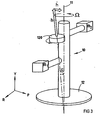
- FIG. 2 A representation of one of the rotational assemblies, such as the parabolic antenna assembly 10, is illustrated in FIG. 2 having equivalent mass representations for the asymmetric configuration.
- the rotational assembly 10 is shown having an equivalent mass m 1 , at a vertical momentum height x 1 and a length 1 1 offset from the axis of rotation 11.
- the rotational assembly 10 has an equivalent mass m 2 at a momentum height x 2 , which is greater than x 1 and a length 1 2 offset from the axis of rotation 11.
- the present invention employs one or more momentum devices for generating a compensation torque that is equal and opposite to the dynamic unbalance moment so as to compensate for the dynamic unbalance, without requiring the addition of a significant amount of weight to the rotational assembly.
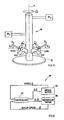
- the rotational assembly 10 is shown having a momentum device, such as a momentum wheel 120, oriented according to a first embodiment of the present invention.
- the momentum wheel 120 is mounted to the rotational assembly 10 along an axis offset by an angle ⁇ offset from the angle of rotation 11 so as to control Y-axis momentum and also provide dynamic unbalance compensation.
- the momentum vector h is sized such that the Y-axis component of momentum is equal to h cos ⁇ , while the torque vector h is equal to h sin ⁇ , such that the resulting compensation torque h is equal and opposite to the dynamic unbalance caused by the asymmetric arrangement of rotation masses m 1 and m 2 .
- the momentum wheel 120 provides the required angular momentum in the Y direction to spin the rotational assembly 10, while a component of the angular momentum h provides the dynamic unbalance compensation.
- a component of the angular momentum h provides the dynamic unbalance compensation.
- the momentum wheel 120 may be fixed mounted to the rotational assembly 10 or mounted in a gimbal assembly (not shown) which would allow adjustment of the orientation angle ⁇ of the momentum wheel 120. Accordingly, the speed of rotation of the momentum wheel 120, orientation (angle ⁇ ) of the momentum wheel 120, and size of the momentum wheel 120, will determine both the amount the angular momentum about the Y-axis and the dynamic unbalance compensation.
- a momentum device includes a reaction wheel assembly (RWA).
- RWA reaction wheel assembly
- Other momentum wheels may be employed to achieve the desired angular momentum and dynamic unbalance compensation.
- the rotational assembly 10 is shown having a pair of momentum devices 220a and 220b according to a second embodiment of the present invention.
- the pair of momentum devices 220a and 220b may include momentum wheels, oriented to form a scissored pair so as to allow for significant control torque about the axis of rotation 11 while providing augmented dynamic unbalance control.
- the momentum wheels 220a and 220b are shown mounted on opposite sides of the rotating assembly 12, and thus are angularly rotated one hundred eighty degrees (180°) relative to the other.
- the momentum wheels 220a and 220b may otherwise be arranged on the assembly 12.
- the first momentum wheel 220a is shown oriented at an angle ⁇ 1 relative to an axis perpendicular to the axis of rotation 11.
- the second momentum wheel 220b is oriented at angle ⁇ 2 relative to the axis perpendicular to the axis of rotation 11.
- Each of the momentum wheels 220a and 220b are shown mounted to the rotational assembly 10 via gimbals 222 which allow for adjustment of the orientation (angles ⁇ 1 and ⁇ 2) of each of the corresponding momentum wheels.
- the gimbals 222 each include a pair of gimbal mounts fixedly attached to the rotational assembly 10 and a shaft mounted in bearings between the gimbal mounts and rotatable to angularly rotate the momentum shaft.
- the momentum wheels may include a gimbaled reaction wheel.
- the momentum wheel may include a gimbaled reaction wheel driven by a motor or clutch (not shown) for positioning the orientation of the momentum wheels.
- the dynamic unbalance moment created by the scissored pair of momentum wheels 220a and 220b provides a compensation torque that is equal and opposite to the dynamic unbalance. It should be appreciated that additional wheels may provide the ability to achieve enhanced torque control.
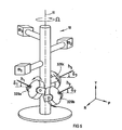
- the rotational assembly 10 is further shown represented with three masses m 1 , m 2 , and m 3 and has three momentum wheel devices 320a-320c equiangularly mounted thereto every one hundred twenty degrees (120°) around the rotational assembly 10.
- the three momentum wheels 220a-220c may otherwise be arranged on the assembly 12.
- the first momentum wheel 320a is oriented at an angle ⁇ 1 relative to an axis perpendicular to the axis of rotation 11 and generates angular momentum h 1 .
- the second momentum wheel 220b is oriented at an angle ⁇ 2 relative to the axis perpendicular to the axis perpendicular to the axis of rotation 11 and generates a second angular momentum h 2 .
- the third momentum wheel 220c is oriented at an angle ⁇ 3 relative to the axis perpendicular to the axis of rotation 11 and generates an angular momentum h 3 .
- Each of the momentum wheels 320A-320C is mounted on a gimbal 322 which allows for adjustment of the orientation (angles ⁇ 1 , ⁇ 2 , and ⁇ 3 ) of each of the momentum wheels.
- three axes torque and momentum control can be achieved such that any unwanted cross torque is reduced or eliminated from the rotational assembly 10 and dynamic unbalance compensation can be achieved at various rotational rates.
- the three momentum devices 320a-320c may form a gimbaled momentum system, such as a control moment gyroscope (CMG) array which allows three axis momentum control as well as dynamic unbalance compensation without emitting unwanted torque to the whole structure.
- CMG control moment gyroscope
- Momentum control for such a system can be controlled through rotor speed of the individual momentum wheels and/or by changing the gimbal orientation of the corresponding momentum wheels 320a-320c.
- each of the above-described embodiments of employing one or more momentum devices to compensate for dynamic unbalance of a rotational assembly 10 may further employ an active control system, such as the feedback control system shown in FIG 6, to provide for active control having a variable range of dynamic unbalance compensation.
- the control system may include a controller 32, a gimbal motor 34, and a momentum rotor 36, and may further include sensors, such as a rotor speed sensor and gimbal angle sensor (not shown).
- the controller 32 monitors the angle ⁇ of the gimbal motor as well as the rotor speed ⁇ of the momentum device(s) and provides an angular control signal ⁇ to control the angle ⁇ of the gimbal motor 34, as well as a speed control signal ⁇ to control the speed ⁇ of the momentum rotor 36. It should be appreciated that by controlling the rotor speed ⁇ and orientation ⁇ of the gimbal, the momentum device(s) may be adjusted to achieve enhanced dynamic unbalance compensation. The controller 32 may further control spin-up and spin-down of the payload of the rotational assembly 10, while simultaneously adjusting the momentum compensation to adjust for changes in the dynamic unbalance.
- the rotational assembly 10 advantageously provides for dynamic balance compensation without adding significant weight to the rotational assembly 10.
- the rotational assembly 10 is less susceptible to pointing errors which may otherwise result on a satellite spacecraft.
- the rotational assembly 10 is shown employing one, two, or three momentum devices, it should be appreciated that any number and various types of momentum devices may be employed without departing from the teachings of the present invention.
- the dynamic unbalance compensation system of the present invention may also be useful for the field of robotics and precision instrument controls, in addition to use on spacecraft.
Landscapes
- Engineering & Computer Science (AREA)
- Remote Sensing (AREA)
- Aviation & Aerospace Engineering (AREA)
- Chemical & Material Sciences (AREA)
- Combustion & Propulsion (AREA)
- Radar, Positioning & Navigation (AREA)
- General Engineering & Computer Science (AREA)
- Physics & Mathematics (AREA)
- Acoustics & Sound (AREA)
- Mechanical Engineering (AREA)
- Control Of Position, Course, Altitude, Or Attitude Of Moving Bodies (AREA)
- Variable-Direction Aerials And Aerial Arrays (AREA)
Claims (13)
- Système à compensation de déséquilibre dynamique, ledit système comprenant :un élément de support (18) ;un ensemble rotatif (10) monté sur l'élément de support et pouvant tourner autour d'un axe de rotation (11) par rapport à l'élément de support, et un ou plusieurs dispositifs d'inertie (120, 220, 320) montés sur l'ensemble rotatif, chaque dispositif d'inertie générant une première composante de vecteur d'inertie perpendiculaire à l'axe de rotation, de façon à générer un couple de compensation quand l'ensemble de rotation tourne et compenser le déséquilibre dynamique de l'ensemble rotatif, caractérisé en ce que :chaque dispositif d'inertie est monté par l'intermédiaire d'un ensemble de cardan (222, 322) de façon à permettre le réglage de l'angle d'orientation de son vecteur d'inertie dans un plan parallèle à l'axe de rotation de l'ensemble rotatif, et à générer une deuxième composante du vecteur d'inertie parallèle à l'axe de rotation et comprenant aussi un contrôleur (32) pour commander la vitesse et l'orientation de chaque dispositif d'inertie de façon à commander son vecteur d'inertie et à réaliser une compensation à la fois du moment angulaire et du déséquilibre dynamique de l'ensemble rotatif.
- Système selon la revendication 1, dans lequel les un ou plusieurs dispositifs d'inertie (120, 220, 320) comprennent un volant d'inertie rotatif.
- Système selon la revendication 1, dans lequel les un ou plusieurs dispositifs d'inertie (120, 220, 320) comprennent un premier dispositif d'inertie et un deuxième dispositif d'inertie.
- Système selon la revendication 3, dans lequel les premier et deuxième dispositifs d'inertie forment une paire en ciseaux.
- Système selon la revendication 1, dans lequel les un ou plusieurs dispositifs d'inertie (120, 220, 320) comprennent des premier, deuxième et troisième dispositifs d'inertie.
- Système selon la revendication 5, dans lequel les premier, deuxième et troisième dispositifs d'inertie sont montés sur l'ensemble rotatif (10) d'une manière angulairement équidistante par rapport à l'axe de rotation.
- Système selon la revendication 1, dans lequel l'élément de support comprend un véhicule.
- Système selon la revendication 7, dans lequel le véhicule comprend un engin spatial.
- Système selon la revendication 1, dans lequel l'ensemble rotatif comprend un instrument.
- Procédé d'équilibrage d'un système présentant un déséquilibre dynamique, ledit procédé comprenant les étapes de :fourniture d'un élément de support (18) sur lequel est monté un ensemble rotatif ;rotation de l'ensemble rotatif autour d'un axe de rotation (11) par rapport à l'élément de support ; etgénération d'une première composante de vecteur d'inertie, avec au moins un dispositif d'inertie (120, 220, 320), perpendiculaire à l'axe de rotation, de façon à générer un couple de compensation pour compenser le déséquilibre dynamique de l'ensemble rotatif en rotation ; caractérisé par :le montage de chaque dispositif d'inertie par l'intermédiaire d'un ensemble de cardan (222, 322) de façon à permettre le réglage de l'angle d'orientation de son vecteur d'inertie dans un plan parallèle à l'axe de rotation de l'ensemble rotatif, et à générer une deuxième composante du vecteur d'inertie parallèle à l'axe de rotation, et par les étapes de :commande de la vitesse et de l'orientation de chaque dispositif d'inertie de façon à commander son vecteur d'inertie et à réaliser une compensation à la fois du moment angulaire et du déséquilibre dynamique de l'ensemble rotatif.
- Procédé selon la revendication 10, dans lequel la génération d'une première composante de vecteur d'inertie comprend la rotation d'un volant d'inertie.
- Procédé selon la revendication 11, dans lequel l'étape de génération d'une première composante de vecteur d'inertie comprend la génération d'une première composante de vecteur avec un premier dispositif d'inertie et un deuxième dispositif d'inertie.
- Procédé selon la revendication 12, dans lequel l'étape de génération d'une première composante de vecteur d'inertie comprend en outre la génération de la première composante de vecteur d'inertie.
Applications Claiming Priority (3)
| Application Number | Priority Date | Filing Date | Title |
|---|---|---|---|
| US81639 | 1993-06-24 | ||
| US10/081,639 US6772978B2 (en) | 2002-02-22 | 2002-02-22 | Dynamic unbalance compensation system and method |
| PCT/US2003/005349 WO2003072436A1 (fr) | 2002-02-22 | 2003-02-21 | Procede et systeme de compensation de desequilibre dynamique |
Publications (2)
| Publication Number | Publication Date |
|---|---|
| EP1476357A1 EP1476357A1 (fr) | 2004-11-17 |
| EP1476357B1 true EP1476357B1 (fr) | 2007-04-11 |
Family
ID=27752976
Family Applications (1)
| Application Number | Title | Priority Date | Filing Date |
|---|---|---|---|
| EP03713604A Expired - Lifetime EP1476357B1 (fr) | 2002-02-22 | 2003-02-21 | Procede et systeme de compensation de desequilibre dynamique |
Country Status (5)
| Country | Link |
|---|---|
| US (1) | US6772978B2 (fr) |
| EP (1) | EP1476357B1 (fr) |
| AU (1) | AU2003217647A1 (fr) |
| DE (1) | DE60313133T2 (fr) |
| WO (1) | WO2003072436A1 (fr) |
Families Citing this family (15)
| Publication number | Priority date | Publication date | Assignee | Title |
|---|---|---|---|---|
| US7448854B2 (en) | 2004-08-30 | 2008-11-11 | Lord Corporation | Helicopter vibration control system and rotary force generator for canceling vibrations |
| US8090482B2 (en) | 2007-10-25 | 2012-01-03 | Lord Corporation | Distributed active vibration control systems and rotary wing aircraft with suppressed vibrations |
| US7722322B2 (en) | 2004-08-30 | 2010-05-25 | Lord Corporation | Computer system and program product for controlling vibrations |
| US8162606B2 (en) | 2004-08-30 | 2012-04-24 | Lord Corporation | Helicopter hub mounted vibration control and circular force generation systems for canceling vibrations |
| US8267652B2 (en) | 2004-08-30 | 2012-09-18 | Lord Corporation | Helicopter hub mounted vibration control and circular force generation systems for canceling vibrations |
| NL1027102C2 (nl) * | 2004-09-24 | 2006-03-27 | Univ Delft Tech | Gestel. |
| FR2903029B1 (fr) * | 2006-07-03 | 2010-12-10 | Peugeot Citroen Automobiles Sa | Dispositif pour generer une contre vibration comprenant un rotor muni d'un balourd |
| US20090120217A1 (en) * | 2007-11-13 | 2009-05-14 | Honeywell International, Inc. | Rotor assemblies with adjustable struts |
| EP2344841A4 (fr) * | 2008-10-01 | 2013-05-22 | A Tech Corp | Procédé et appareil de mesure de précision de l azimut |
| RU2501720C1 (ru) * | 2012-09-13 | 2013-12-20 | Федеральное государственное унитарное предприятие "Московское опытно-конструкторское бюро "Марс" (ФГУП МОКБ "Марс") | Способ ориентации космического аппарата и устройство для его реализации |
| RU2519288C1 (ru) * | 2013-02-27 | 2014-06-10 | Федеральное государственное унитарное предприятие "Московское опытно-конструкторское бюро "Марс" (ФГУП МОКБ "Марс") | Способ ориентации космического аппарата и устройство для его реализации |
| RU2536010C1 (ru) * | 2013-07-17 | 2014-12-20 | Федеральное государственное унитарное предприятие "Московское опытно-конструкторское бюро "Марс" (ФГУП МОКБ "Марс") | Способ ориентации космического аппарата и устройство для его реализации |
| ITTO20131067A1 (it) | 2013-12-23 | 2015-06-24 | Thales Alenia Space Italia S P A C On Unico Socio | Sistema di controllo di assetto per applicazioni satellitari agili |
| US11531398B1 (en) * | 2021-08-20 | 2022-12-20 | Apple Inc. | Gyroscopic precession engine for wearable devices |
| DE102023136422B3 (de) * | 2023-12-21 | 2025-06-18 | Deutsches Zentrum für Luft- und Raumfahrt e.V. | Weltraumhandhabungsvorrichtung |
Family Cites Families (10)
| Publication number | Priority date | Publication date | Assignee | Title |
|---|---|---|---|---|
| US3818767A (en) * | 1972-09-29 | 1974-06-25 | Nasa | Passive dual-spin misalignment compensators |
| US4375878A (en) * | 1980-10-28 | 1983-03-08 | Lockheed Missiles & Space Company, Inc. | Space satellite with agile payload orientation system |
| US4458554A (en) * | 1981-02-27 | 1984-07-10 | The United States Of America As Represented By The Administrator Of The National Aeronautics And Space Administration | Apparatus for and method of compensating dynamic unbalance |
| JPS59184835A (ja) * | 1983-04-06 | 1984-10-20 | Mitsubishi Electric Corp | 不つりあい修正装置 |
| US4728062A (en) * | 1985-11-12 | 1988-03-01 | Rca Corporation | Pivot actuated nutation damping for a dual-spin spacecraft |
| US5012992A (en) * | 1988-12-09 | 1991-05-07 | Hughes Aircraft Company | Spin stabilization via momentum wheels or similar devices |
| US5681012A (en) * | 1995-01-05 | 1997-10-28 | Hughes Electronics | Spacecraft control with skewed control moment gyros |
| US6340137B1 (en) * | 1998-08-26 | 2002-01-22 | Honeywell International Inc. | Moment control unit for spacecraft attitude control |
| EP1126300B1 (fr) * | 1999-03-10 | 2008-10-15 | Mitsubishi Heavy Industries, Ltd. | Telescope a reflecteur |
| FR2796172B1 (fr) * | 1999-07-08 | 2001-09-21 | Cit Alcatel | Systeme pour le controle d'un satellite en attitude et procede corespondant |
-
2002
- 2002-02-22 US US10/081,639 patent/US6772978B2/en not_active Expired - Lifetime
-
2003
- 2003-02-21 EP EP03713604A patent/EP1476357B1/fr not_active Expired - Lifetime
- 2003-02-21 AU AU2003217647A patent/AU2003217647A1/en not_active Abandoned
- 2003-02-21 WO PCT/US2003/005349 patent/WO2003072436A1/fr not_active Ceased
- 2003-02-21 DE DE60313133T patent/DE60313133T2/de not_active Expired - Lifetime
Also Published As
| Publication number | Publication date |
|---|---|
| AU2003217647A1 (en) | 2003-09-09 |
| US20030160132A1 (en) | 2003-08-28 |
| US6772978B2 (en) | 2004-08-10 |
| DE60313133T2 (de) | 2007-12-20 |
| DE60313133D1 (de) | 2007-05-24 |
| EP1476357A1 (fr) | 2004-11-17 |
| WO2003072436A1 (fr) | 2003-09-04 |
Similar Documents
| Publication | Publication Date | Title |
|---|---|---|
| EP1476357B1 (fr) | Procede et systeme de compensation de desequilibre dynamique | |
| US5897223A (en) | Stabilized platform system for camera | |
| JP2959696B2 (ja) | 衛星トルク平衡方法および装置 | |
| US7097140B2 (en) | System and method for spacecraft attitude control | |
| US4393597A (en) | Stabilized sighting devices for vehicles | |
| EP1165371B1 (fr) | Systeme de commande d'attitude d'un vaisseau spatial | |
| US5441222A (en) | Attitude control of spinning spacecraft | |
| JPS6085602A (ja) | 船舶上のアンテナの安定化及び照準を行う装置 | |
| EP0819997A2 (fr) | Système de contrÔle d'attitude d'un véhicule spatial | |
| GB2080040A (en) | Passive stabilisation system for tracking antennas | |
| JP7576628B2 (ja) | 太陽エネルギーを追跡するシステム | |
| US4272045A (en) | Nutation damping in a dual-spin spacecraft | |
| CA1282393C (fr) | Systeme amortisseur de nutation commande par pivot pour engin spatial a deux coordonnees de rotation | |
| US6789437B2 (en) | Apparatus for precision slewing of flatform-mounted devices | |
| Tyc et al. | Gyrowheel™-An Innovative New Actuator/Sensor for 3-axis Spacecraft Attitude Control | |
| US6191749B1 (en) | Arrangement comprising an antenna reflector and a transceiver horn combined to form a compact antenna unit | |
| US4976163A (en) | Reactionless actuator-gimbal system | |
| US6196502B1 (en) | Attitude control of spinning spacecraft with counterspun controls platform | |
| EP0209216B1 (fr) | Dispositif de stabilisation d'une plateforme d'antenne | |
| JPH06132716A (ja) | アンテナ姿勢制御装置 | |
| US20090120217A1 (en) | Rotor assemblies with adjustable struts | |
| Phillips | Nutation damping in a dual-spin spacecraft | |
| JPH0335843B2 (fr) | ||
| JPH0335842B2 (fr) | ||
| JPH05291811A (ja) | アンテナ指向装置 |
Legal Events
| Date | Code | Title | Description |
|---|---|---|---|
| PUAI | Public reference made under article 153(3) epc to a published international application that has entered the european phase |
Free format text: ORIGINAL CODE: 0009012 |
|
| 17P | Request for examination filed |
Effective date: 20040901 |
|
| AK | Designated contracting states |
Kind code of ref document: A1 Designated state(s): AT BE BG CH CY CZ DE DK EE ES FI FR GB GR HU IE IT LI LU MC NL PT SE SI SK TR |
|
| AX | Request for extension of the european patent |
Extension state: AL LT LV MK RO |
|
| 17Q | First examination report despatched |
Effective date: 20050308 |
|
| GRAP | Despatch of communication of intention to grant a patent |
Free format text: ORIGINAL CODE: EPIDOSNIGR1 |
|
| GRAS | Grant fee paid |
Free format text: ORIGINAL CODE: EPIDOSNIGR3 |
|
| GRAA | (expected) grant |
Free format text: ORIGINAL CODE: 0009210 |
|
| RAP1 | Party data changed (applicant data changed or rights of an application transferred) |
Owner name: HONEYWELL INTERNATIONAL INC. |
|
| AK | Designated contracting states |
Kind code of ref document: B1 Designated state(s): DE FR GB IT |
|
| REG | Reference to a national code |
Ref country code: GB Ref legal event code: FG4D |
|
| REF | Corresponds to: |
Ref document number: 60313133 Country of ref document: DE Date of ref document: 20070524 Kind code of ref document: P |
|
| EN | Fr: translation not filed | ||
| PLBE | No opposition filed within time limit |
Free format text: ORIGINAL CODE: 0009261 |
|
| STAA | Information on the status of an ep patent application or granted ep patent |
Free format text: STATUS: NO OPPOSITION FILED WITHIN TIME LIMIT |
|
| 26N | No opposition filed |
Effective date: 20080114 |
|
| PG25 | Lapsed in a contracting state [announced via postgrant information from national office to epo] |
Ref country code: IT Free format text: LAPSE BECAUSE OF FAILURE TO SUBMIT A TRANSLATION OF THE DESCRIPTION OR TO PAY THE FEE WITHIN THE PRESCRIBED TIME-LIMIT Effective date: 20070411 Ref country code: FR Free format text: LAPSE BECAUSE OF FAILURE TO SUBMIT A TRANSLATION OF THE DESCRIPTION OR TO PAY THE FEE WITHIN THE PRESCRIBED TIME-LIMIT Effective date: 20071207 |
|
| PG25 | Lapsed in a contracting state [announced via postgrant information from national office to epo] |
Ref country code: FR Free format text: LAPSE BECAUSE OF FAILURE TO SUBMIT A TRANSLATION OF THE DESCRIPTION OR TO PAY THE FEE WITHIN THE PRESCRIBED TIME-LIMIT Effective date: 20070411 |
|
| PGFP | Annual fee paid to national office [announced via postgrant information from national office to epo] |
Ref country code: GB Payment date: 20100107 Year of fee payment: 8 |
|
| GBPC | Gb: european patent ceased through non-payment of renewal fee |
Effective date: 20110221 |
|
| PG25 | Lapsed in a contracting state [announced via postgrant information from national office to epo] |
Ref country code: GB Free format text: LAPSE BECAUSE OF NON-PAYMENT OF DUE FEES Effective date: 20110221 |
|
| PGFP | Annual fee paid to national office [announced via postgrant information from national office to epo] |
Ref country code: DE Payment date: 20160302 Year of fee payment: 14 |
|
| REG | Reference to a national code |
Ref country code: DE Ref legal event code: R119 Ref document number: 60313133 Country of ref document: DE |
|
| PG25 | Lapsed in a contracting state [announced via postgrant information from national office to epo] |
Ref country code: DE Free format text: LAPSE BECAUSE OF NON-PAYMENT OF DUE FEES Effective date: 20170901 |
|
| P01 | Opt-out of the competence of the unified patent court (upc) registered |
Effective date: 20230525 |