EP1477247B1 - Modulare Vorschubeinrichtung mit rechtwinkliger Einstellung der Vorschubrichtung - Google Patents
Modulare Vorschubeinrichtung mit rechtwinkliger Einstellung der Vorschubrichtung Download PDFInfo
- Publication number
- EP1477247B1 EP1477247B1 EP04010001A EP04010001A EP1477247B1 EP 1477247 B1 EP1477247 B1 EP 1477247B1 EP 04010001 A EP04010001 A EP 04010001A EP 04010001 A EP04010001 A EP 04010001A EP 1477247 B1 EP1477247 B1 EP 1477247B1
- Authority
- EP
- European Patent Office
- Prior art keywords
- modules
- right angle
- flow direction
- fact
- press
- Prior art date
- Legal status (The legal status is an assumption and is not a legal conclusion. Google has not performed a legal analysis and makes no representation as to the accuracy of the status listed.)
- Expired - Lifetime
Links
- 238000000034 method Methods 0.000 claims description 9
- 230000007246 mechanism Effects 0.000 claims description 6
- 230000001360 synchronised effect Effects 0.000 claims 2
- NJPPVKZQTLUDBO-UHFFFAOYSA-N novaluron Chemical compound C1=C(Cl)C(OC(F)(F)C(OC(F)(F)F)F)=CC=C1NC(=O)NC(=O)C1=C(F)C=CC=C1F NJPPVKZQTLUDBO-UHFFFAOYSA-N 0.000 claims 1
- 238000009434 installation Methods 0.000 description 2
- 238000004519 manufacturing process Methods 0.000 description 1
- 239000002184 metal Substances 0.000 description 1
Images

Classifications
-
- B—PERFORMING OPERATIONS; TRANSPORTING
- B21—MECHANICAL METAL-WORKING WITHOUT ESSENTIALLY REMOVING MATERIAL; PUNCHING METAL
- B21D—WORKING OR PROCESSING OF SHEET METAL OR METAL TUBES, RODS OR PROFILES WITHOUT ESSENTIALLY REMOVING MATERIAL; PUNCHING METAL
- B21D43/00—Feeding, positioning or storing devices combined with, or arranged in, or specially adapted for use in connection with, apparatus for working or processing sheet metal, metal tubes or metal profiles; Associations therewith of cutting devices
- B21D43/02—Advancing work in relation to the stroke of the die or tool
- B21D43/04—Advancing work in relation to the stroke of the die or tool by means in mechanical engagement with the work
- B21D43/05—Advancing work in relation to the stroke of the die or tool by means in mechanical engagement with the work specially adapted for multi-stage presses
- B21D43/055—Devices comprising a pair of longitudinally and laterally movable parallel transfer bars
Definitions
- the present invention relates to a modular transfer system suitable for being applied to the processing of metal parts that are stamped in presses, and normally processed through various sequence stages in one single press; the process is commonly called Transfer.
- the transfer systems currently installed in presses are characteristic for operating a linear transportation of the parts, in a direction that is defined during the project / manufacture / installation; that is to say, length or crosswise of the press; however, we do not know of any transfer that can be operated in either way according to the programming required and to the characteristics of the parts and processes.
- modules must be placed and assembled so as to meet the part and process specifications in both flows; they are normally assembled on a base and placed in the corners next to the columns of the press.
- Another assembly alternative is to assemble such modules on appropriate stands that are joined to the press columns instead of being fixed.
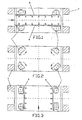
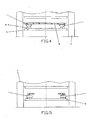
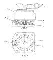
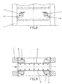
- the modular transfer system with right angle turn in the flow direction in focus herein is basically made up of a group of modules (1) generally four of them, each one being assembled on a revolving platform (2) placed on a fixed base (3) equipped with a lock (4) that positions the (90° degree) turn, while the aforesaid base is fixed onto the table (5).
- the modules (1) presented herein are based on an operating system described in a Brazilian patent filed by the same holder under no. (PI) 960612 (& EP-A-0849015).
- This document discloses a transfer comprising four modules with mechanisms and a motorized system, said modules being installed so as to enable the assembly of the transfer rails two by two, said rails having grippers to transfer the parts processed in the press.
- the module (1) is an independent mechanical and motorized unit, whose mechanism moves on 2 to 3 axes of the rails (6) and, consequently, these have fixed grippers to hold the parts to stamp.
- modules also have motors to operate the mechanism that displaces the parts along the "X" axis (horizontally/pitch), "Y” axis (to close/open the rails), and “Z” axis (to go up/down), whereby the "X” axis is operated by using only two motors, installed on diagonally opposed modules (any diagonal), as the forward/backward movement of the rails occurs only at one point on each side of the rails (6) inside the press (7) both length and crosswise, between the stages, during which the dies are used to stamp the parts, in a continuous and preprogrammed cycle. It is important to stress that the most appropriate method known must be used to turn the modules (1) and place them adequately so as to operate them either cross or lengthwise of the press / transfer axis, using a pneumatic, electric, or any other means judged more appropriate for the operation.
- modules are turned independently within a 90° degree angle, each module being placed so as to receive the rails (6) used to move the parts to stamp or blank.
- An option is to have modules (1) that can be assembled on stands (8) joined to the columns of the press and that can preferably be removed to replace dies.
Landscapes
- Engineering & Computer Science (AREA)
- Mechanical Engineering (AREA)
- Mounting, Exchange, And Manufacturing Of Dies (AREA)
- Press Drives And Press Lines (AREA)
Claims (9)
- Modulares Transfersystem mit rechtwinkliger Erstellung der Vorschubrichtung, mit 4 unabhängigen Modulen (1) mit Mechaniken und einem Motorsystem, welche dennoch synchron arbeiten, wobei die Module auf Drehbasen (2) montiert sind, die eine 90°-Kehre ermöglichen, um den Fluss des Prozesses senkrecht zu der Presse (7) zu ändern, und geeignet installiert sind, um die Montage der Schienen (6) in Zweiergruppen zu ermöglichen, wobei die Schienen (6) Greifer zum Transferieren der in der Presse (7) verarbeiteten Teile aufweisen.
- Modulares Transfersystem mit rechtwinkliger Erstellung der Vorschubrichtung, gemäß Anspruch 1, gekennzeichnet durch den Umstand, dass die Module (1) einen unabhängigen Antriebsmechanismus für die "Y"- und "Z"-Achsen aufweisen.
- Modulares Transfersystem mit rechtwinkliger Erstellung der Vorschubrichtung, gemäß Anspruch 1 oder 2, gekennzeichnet durch den Umstand, dass die Module (1) ein Antriebssystem für die "X"-Achse aufweisen, das auf den Modulen (1) montiert und diagonal einander gegenüber angeordnet ist.
- Modulares Transfersystem mit rechtwinkliger Erstellung der Vorschubrichtung, gemäß Anspruch 1 oder 2, gekennzeichnet durch den Umstand, dass die Module (1) ein unabhängiges Antriebssystem für die "X"-Achse aufweisen, das auf jedem Modul (1) montiert ist.
- Modulares Transfersystem mit rechtwinkliger Erstellung der Vorschubrichtung, gemäß einem der Ansprüche 1 bis 4, gekennzeichnet durch den Umstand, dass sich die Module (1) auf eine unabhängige oder austauschbare Weise drehen, doch simultan und um 90° Grad, um einen rechten Winkel zu bilden, wodurch die Richtung der zu stanzenden Teile so geändert wird, dass sie dazu gebracht werden, von einer Quer- zu einer Längsposition innerhalb der Presse (7) zu gelangen und die mit Greifern ausgestatteten traditionellen Schienen (6) zum Transferieren der Teile während des Prozesses zu verwenden.
- Modulares Transfersystem mit rechtwinkliger Erstellung der Vorschubrichtung, gemäß einem der Ansprüche 1 bis 5, gekennzeichnet durch den Umstand, dass die Module (1) auf einer Basis (3) oder auf einer Basis auf dem Sockel der Presse (7) montiert und in die Stanzstufen innerhalb des Transfergebietes integriert sind.
- Modulares Transfersystem mit rechtwinkliger Erstellung der Vorschubrichtung, gemäß einem der Ansprüche 1 bis 5, gekennzeichnet durch den Umstand, dass die Module (1) auf Ständern (8) montiert sind, die auf jeder Säule der Presse (7) montiert sind.
- Modulares Transfersystem mit rechtwinkliger Erstellung der Vorschubrichtung, gemäß Anspruch 7, gekennzeichnet durch den Umstand, dass die Ständer (8) Mittel für angemessene Verlagerung aufweisen, um den Stempel während der Stufen des Pressprozesses zu platzieren und zurückzuziehen.
- Modulares Transfersystem mit rechtwinkliger Erstellung der Vorschubrichtung, gemäß einem der Ansprüche 1 bis 8, gekennzeichnet durch den Umstand, dass das Antriebssystem der Transfermodule (1) auf einem zentralen Steuersystem montiert ist, wodurch sämtliche Bewegungen synchronisiert werden, so dass sich die Ständer auf eine synchronisierte und zweckmäßige Weise verlagern.
Applications Claiming Priority (2)
| Application Number | Priority Date | Filing Date | Title |
|---|---|---|---|
| BR0305689-9A BR0305689A (pt) | 2003-04-27 | 2003-04-27 | Transfer modular com giro ortogonal no sentido do fluxo |
| BR0305689 | 2003-04-28 |
Publications (2)
| Publication Number | Publication Date |
|---|---|
| EP1477247A1 EP1477247A1 (de) | 2004-11-17 |
| EP1477247B1 true EP1477247B1 (de) | 2006-06-14 |
Family
ID=35135060
Family Applications (1)
| Application Number | Title | Priority Date | Filing Date |
|---|---|---|---|
| EP04010001A Expired - Lifetime EP1477247B1 (de) | 2003-04-27 | 2004-04-27 | Modulare Vorschubeinrichtung mit rechtwinkliger Einstellung der Vorschubrichtung |
Country Status (5)
| Country | Link |
|---|---|
| US (1) | US7017383B2 (de) |
| EP (1) | EP1477247B1 (de) |
| BR (1) | BR0305689A (de) |
| DE (1) | DE602004001165T2 (de) |
| ES (1) | ES2266952T3 (de) |
Families Citing this family (1)
| Publication number | Priority date | Publication date | Assignee | Title |
|---|---|---|---|---|
| US7971468B2 (en) * | 2008-07-23 | 2011-07-05 | Hms Products Co. | Part transfer system and method |
Family Cites Families (8)
| Publication number | Priority date | Publication date | Assignee | Title |
|---|---|---|---|---|
| SE452753B (sv) * | 1983-05-31 | 1987-12-14 | Komatsu Mfg Co Ltd | Anordning for lastning och/eller urlastning av arbetsstycken i och/eller fran en press eller liknande bearbetningsmaskin |
| US5140839A (en) * | 1991-06-27 | 1992-08-25 | Hitachi Zosen Clearing, Inc. | Cross bar transfer press |
| US5390525A (en) * | 1993-12-02 | 1995-02-21 | Rapindex Incorporated | Indexing conveyor for a die transfer system |
| DE19506078A1 (de) * | 1995-02-22 | 1996-08-29 | Schuler Pressen Gmbh & Co | Vorrichtung zum Transfer von Werkstücken durch eine Folge von Bearbeitungsstationen |
| US5701781A (en) * | 1996-07-09 | 1997-12-30 | Livernois Research & Development Company | System and method for controlling movement of a transfer system |
| BR9606122A (pt) * | 1996-12-20 | 1998-09-08 | Sousa Monteiro Luciano T De | Dispositivo mecânico aplicado em sistema de transferência |
| DE19720518A1 (de) * | 1997-05-16 | 1998-11-19 | Schuler Pressen Gmbh & Co | Transferpresse mit seitlicher Toolingablage |
| FR2784915B1 (fr) * | 1998-10-26 | 2001-01-26 | Peugeot | Dispositif de transfert d'une piece entre deux postes d'un outil d'une presse |
-
2003
- 2003-04-27 BR BR0305689-9A patent/BR0305689A/pt not_active IP Right Cessation
-
2004
- 2004-04-27 DE DE602004001165T patent/DE602004001165T2/de not_active Expired - Fee Related
- 2004-04-27 US US10/833,336 patent/US7017383B2/en not_active Expired - Fee Related
- 2004-04-27 ES ES04010001T patent/ES2266952T3/es not_active Expired - Lifetime
- 2004-04-27 EP EP04010001A patent/EP1477247B1/de not_active Expired - Lifetime
Also Published As
| Publication number | Publication date |
|---|---|
| DE602004001165D1 (de) | 2006-07-27 |
| US7017383B2 (en) | 2006-03-28 |
| ES2266952T3 (es) | 2007-03-01 |
| US20050235727A1 (en) | 2005-10-27 |
| DE602004001165T2 (de) | 2007-05-10 |
| BR0305689A (pt) | 2005-05-17 |
| EP1477247A1 (de) | 2004-11-17 |
Similar Documents
| Publication | Publication Date | Title |
|---|---|---|
| US8397375B2 (en) | Modular transfer system for workpieces | |
| US5722283A (en) | System and method for rotation of cross bars in a multiple station transfer press | |
| GB2212421A (en) | Work support and positioning device for assembly line | |
| AU702193B2 (en) | Multi-stage assembling robot | |
| JP2019535521A (ja) | 操作装置を有する製造設備 | |
| JP2562461B2 (ja) | 型鍛造プレス又は類似のものの工作実搬送装置 | |
| US20070284216A1 (en) | Workpiece Machining Method and Workpiece Machining Device for a Transfer System With Machining Carried Out on a Number of Sides | |
| DE4309643C2 (de) | Umsetzeinrichtung für den Werkstücktransport | |
| US4887446A (en) | System for transferring workpieces through a series of work stations | |
| US10058964B2 (en) | Transport device for transporting a work piece along consecutive processing stations of a production installation, a production installation, a multistage forming press, and a method for manufacturing products from work pieces by means of a production installation | |
| CN1913987B (zh) | 用于压力机内工件的输送装置 | |
| EP1477247B1 (de) | Modulare Vorschubeinrichtung mit rechtwinkliger Einstellung der Vorschubrichtung | |
| US6442829B1 (en) | Production and/or assembly apparatus | |
| JPS59163038A (ja) | トランスフアプレスにおけるワ−ク搬送用フインガ−の位置調整装置 | |
| CN113084533B (zh) | 双根同步穿角码机 | |
| JP2008517770A (ja) | ワークピースの搬送及び位置変更装置 | |
| JPH10328766A (ja) | トランスファプレス搬送装置 | |
| US7159439B2 (en) | Automatic control of intermediate pieces in a bending press | |
| EP2524742B1 (de) | Getaktetes Presswerk | |
| JP2708918B2 (ja) | 一連の加工ステーションを通して加工物を移送するためのシステム | |
| KR100495169B1 (ko) | 공작기계용이송구조 | |
| CN1938125A (zh) | 工件的模块化输送系统 | |
| JP4951445B2 (ja) | プレス設備のワーク自動搬送装置 | |
| US6910362B2 (en) | Tilt mechanism for a transfer rail in a press transfer system | |
| JPH05261461A (ja) | コイルばね成形機械 |
Legal Events
| Date | Code | Title | Description |
|---|---|---|---|
| PUAI | Public reference made under article 153(3) epc to a published international application that has entered the european phase |
Free format text: ORIGINAL CODE: 0009012 |
|
| AK | Designated contracting states |
Kind code of ref document: A1 Designated state(s): AT BE BG CH CY CZ DE DK EE ES FI FR GB GR HU IE IT LI LU MC NL PL PT RO SE SI SK TR |
|
| AX | Request for extension of the european patent |
Extension state: AL HR LT LV MK |
|
| 17P | Request for examination filed |
Effective date: 20050517 |
|
| AKX | Designation fees paid |
Designated state(s): DE ES GB IT |
|
| GRAP | Despatch of communication of intention to grant a patent |
Free format text: ORIGINAL CODE: EPIDOSNIGR1 |
|
| GRAS | Grant fee paid |
Free format text: ORIGINAL CODE: EPIDOSNIGR3 |
|
| GRAA | (expected) grant |
Free format text: ORIGINAL CODE: 0009210 |
|
| AK | Designated contracting states |
Kind code of ref document: B1 Designated state(s): DE ES GB IT |
|
| PG25 | Lapsed in a contracting state [announced via postgrant information from national office to epo] |
Ref country code: IT Free format text: LAPSE BECAUSE OF FAILURE TO SUBMIT A TRANSLATION OF THE DESCRIPTION OR TO PAY THE FEE WITHIN THE PRESCRIBED TIME-LIMIT;WARNING: LAPSES OF ITALIAN PATENTS WITH EFFECTIVE DATE BEFORE 2007 MAY HAVE OCCURRED AT ANY TIME BEFORE 2007. THE CORRECT EFFECTIVE DATE MAY BE DIFFERENT FROM THE ONE RECORDED. Effective date: 20060614 |
|
| REG | Reference to a national code |
Ref country code: GB Ref legal event code: FG4D |
|
| REF | Corresponds to: |
Ref document number: 602004001165 Country of ref document: DE Date of ref document: 20060727 Kind code of ref document: P |
|
| REG | Reference to a national code |
Ref country code: ES Ref legal event code: FG2A Ref document number: 2266952 Country of ref document: ES Kind code of ref document: T3 |
|
| PLBE | No opposition filed within time limit |
Free format text: ORIGINAL CODE: 0009261 |
|
| STAA | Information on the status of an ep patent application or granted ep patent |
Free format text: STATUS: NO OPPOSITION FILED WITHIN TIME LIMIT |
|
| 26N | No opposition filed |
Effective date: 20070315 |
|
| PGFP | Annual fee paid to national office [announced via postgrant information from national office to epo] |
Ref country code: ES Payment date: 20080424 Year of fee payment: 5 |
|
| PGFP | Annual fee paid to national office [announced via postgrant information from national office to epo] |
Ref country code: IT Payment date: 20080426 Year of fee payment: 5 |
|
| PGRI | Patent reinstated in contracting state [announced from national office to epo] |
Ref country code: IT Effective date: 20080601 |
|
| PGFP | Annual fee paid to national office [announced via postgrant information from national office to epo] |
Ref country code: DE Payment date: 20080630 Year of fee payment: 5 |
|
| GBPC | Gb: european patent ceased through non-payment of renewal fee |
Effective date: 20080427 |
|
| PG25 | Lapsed in a contracting state [announced via postgrant information from national office to epo] |
Ref country code: GB Free format text: LAPSE BECAUSE OF NON-PAYMENT OF DUE FEES Effective date: 20080427 |
|
| PG25 | Lapsed in a contracting state [announced via postgrant information from national office to epo] |
Ref country code: DE Free format text: LAPSE BECAUSE OF NON-PAYMENT OF DUE FEES Effective date: 20091103 |
|
| REG | Reference to a national code |
Ref country code: ES Ref legal event code: FD2A Effective date: 20090428 |
|
| PG25 | Lapsed in a contracting state [announced via postgrant information from national office to epo] |
Ref country code: ES Free format text: LAPSE BECAUSE OF NON-PAYMENT OF DUE FEES Effective date: 20090428 |
|
| PG25 | Lapsed in a contracting state [announced via postgrant information from national office to epo] |
Ref country code: IT Free format text: LAPSE BECAUSE OF NON-PAYMENT OF DUE FEES Effective date: 20090427 |