EP1477259B1 - Gas-Economiser with automatic ignition and control for oxygen-gas burners - Google Patents
Gas-Economiser with automatic ignition and control for oxygen-gas burners Download PDFInfo
- Publication number
- EP1477259B1 EP1477259B1 EP04076374A EP04076374A EP1477259B1 EP 1477259 B1 EP1477259 B1 EP 1477259B1 EP 04076374 A EP04076374 A EP 04076374A EP 04076374 A EP04076374 A EP 04076374A EP 1477259 B1 EP1477259 B1 EP 1477259B1
- Authority
- EP
- European Patent Office
- Prior art keywords
- gas
- torch
- economizer
- switch
- support
- Prior art date
- Legal status (The legal status is an assumption and is not a legal conclusion. Google has not performed a legal analysis and makes no representation as to the accuracy of the status listed.)
- Expired - Lifetime
Links
Images

Classifications
-
- F—MECHANICAL ENGINEERING; LIGHTING; HEATING; WEAPONS; BLASTING
- F23—COMBUSTION APPARATUS; COMBUSTION PROCESSES
- F23Q—IGNITION; EXTINGUISHING-DEVICES
- F23Q3/00—Igniters using electrically-produced sparks
- F23Q3/002—Igniters using electrically-produced sparks using piezoelectric elements
-
- B—PERFORMING OPERATIONS; TRANSPORTING
- B23—MACHINE TOOLS; METAL-WORKING NOT OTHERWISE PROVIDED FOR
- B23K—SOLDERING OR UNSOLDERING; WELDING; CLADDING OR PLATING BY SOLDERING OR WELDING; CUTTING BY APPLYING HEAT LOCALLY, e.g. FLAME CUTTING; WORKING BY LASER BEAM
- B23K5/00—Gas flame welding
- B23K5/22—Auxiliary equipment, e.g. backings, guides
- B23K5/24—Arrangements for supporting torches
-
- B—PERFORMING OPERATIONS; TRANSPORTING
- B23—MACHINE TOOLS; METAL-WORKING NOT OTHERWISE PROVIDED FOR
- B23K—SOLDERING OR UNSOLDERING; WELDING; CLADDING OR PLATING BY SOLDERING OR WELDING; CUTTING BY APPLYING HEAT LOCALLY, e.g. FLAME CUTTING; WORKING BY LASER BEAM
- B23K7/00—Cutting, scarfing, or desurfacing by applying flames
- B23K7/10—Auxiliary devices, e.g. for guiding or supporting the torch
-
- F—MECHANICAL ENGINEERING; LIGHTING; HEATING; WEAPONS; BLASTING
- F23—COMBUSTION APPARATUS; COMBUSTION PROCESSES
- F23D—BURNERS
- F23D14/00—Burners for combustion of a gas, e.g. of a gas stored under pressure as a liquid
- F23D14/46—Details
- F23D14/465—Details for torches
-
- F—MECHANICAL ENGINEERING; LIGHTING; HEATING; WEAPONS; BLASTING
- F23—COMBUSTION APPARATUS; COMBUSTION PROCESSES
- F23D—BURNERS
- F23D2207/00—Ignition devices associated with burner
-
- F—MECHANICAL ENGINEERING; LIGHTING; HEATING; WEAPONS; BLASTING
- F23—COMBUSTION APPARATUS; COMBUSTION PROCESSES
- F23N—REGULATING OR CONTROLLING COMBUSTION
- F23N2227/00—Ignition or checking
- F23N2227/22—Pilot burners
- F23N2227/24—Pilot burners the pilot burner not burning continuously
-
- F—MECHANICAL ENGINEERING; LIGHTING; HEATING; WEAPONS; BLASTING
- F23—COMBUSTION APPARATUS; COMBUSTION PROCESSES
- F23N—REGULATING OR CONTROLLING COMBUSTION
- F23N2227/00—Ignition or checking
- F23N2227/28—Ignition circuits
-
- F—MECHANICAL ENGINEERING; LIGHTING; HEATING; WEAPONS; BLASTING
- F23—COMBUSTION APPARATUS; COMBUSTION PROCESSES
- F23N—REGULATING OR CONTROLLING COMBUSTION
- F23N2231/00—Fail safe
- F23N2231/06—Fail safe for flame failures
Definitions
- the object of the present invention is a gas saver for an oxy-gas torch device for flame, welding, reheating, etc. applications according to the preamble of the claim (see, for example, JP-A -58/028924).
- Gas savers are already known, for example, for a welding device whose purpose is to allow the flame of a welding torch to which it is connected to be extinguished when it is pressed against a suitable support. activating by a body of the economizer and without intervening on the regulation of gases (for example oxygen or acetylene) forming the welding gas that arrives at the torch.
- gases for example oxygen or acetylene
- Such a support is functionally associated with a member (mechanical) to interrupt the sending of gas torch when the latter is pressed on the support.
- Economizer body is also associated with a burner which is expelled outwardly a pilot flame, permanently lit, which allows the re-ignition of the torch when it is lifted from the lever and approached said pilot flame.
- the document JP-A-58 028924 describes an automatic ignition device for a gas welding torch according to which a push button arranged on the body of the torch serves, when activated by the operator, to generate sparks by means of an ignition system comprising in particular a motor and an energy storage spring, so as to ignite the gas supplying the torch.
- GB-A-1435586 teaches an improvement of the ignition system of a fuel burner.
- the object of the present invention is to provide a gas saver for manual welding device and other similar applications with oxy-gas torch which offers greater simplicity and user safety for users.
- Another goal is to provide a gas saver that is reliable job.
- an economizer comprises a box body 1, internally hollow and provided with a movable gate 2 to allow access to the interior of the body 1.
- This body is preferably fixed on a support (not shown) who supports him.
- the support 5 comprises an element 6 movable relative to a fixed part 7 integral with the column 3, to which it is connected by one of its ends 8, and to directly support the torch 30
- This mobile element 6 cooperates with a microswitch 10 carried by the fixed part 7.
- the movable element 6 comprises an end 6A shaped to support an end portion 30A of the torch 30. On this end 6A, may be superimposed a movable arm (not shown) acting to retain, with this end, the portion 30A torch.
- a spark generator defining an ignition member 13 of the gas sent to the outside by the torch.
- This member is, for example, a known piezoelectric element.
- the ignition member 13 has a plurality of electrodes 13A protected by a gate 3A located at the end 11 of the column 3.
- the body 1 In the body 1 is present an electrical circuit to which are connected the member 13 and the microswitches 10, not only the solenoid valves 14 and 15 connected to the connectors 17 and 18 respectively for the oxygen (or other oxidizing gas) and fuel gas (for example acetylene or similar) conduits.
- the solenoid valves 14 and 15 connected to the connectors 17 and 18 respectively for the oxygen (or other oxidizing gas) and fuel gas (for example acetylene or similar) conduits.
- the connector 17 (and the respective solenoid valve 14) is connected to a conduit 17A for supplying oxygen and to an outlet or use conduit 17B for sending this oxygen to the torch 30.
- connector 18 (and the respective solenoid valve 15) is connected to a conduit 18A for the supply of fuel gas and to an outlet conduit or supply 18B for sending this gas torch 30.
- the gases mix to form the application gas used for flame applications.
- the oxygen and fuel gas pipes, still separated, in the torch 30 are provided with clean valves operable via the buttons 33 present on the outside of the torch.
- the connectors 17 and 18 are arranged outside the body 1 in correspondence with its side 20.
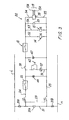
- FIG. 3 Said electric circuit, to which the solenoid valves 14 and 15 are also connected, is shown in FIG. 3 where it is designated 22. It comprises an ON-OFF lever main switch 23 arranged on the outside of the door 2 and connected to electrical lines 24 and 25. These lines are connected, via an electrical branch 21 arranged upstream of the switch 23, to a fixed supply network designated in FIG. 3 by the lines L and N. On the electrical network 21 are arranged an anti-parasitic capacitive filter 21A and fuses 21B. On the electrical line 24 is located a switch 26 (operable via a pusher on the gate 2 where is indicated 26A) acting as a security element to cut or activate the circuit, despite the latter is maintained electrically powered by a network external supply via the closing of the main switch 23.
- a switch 26 (operable via a pusher on the gate 2 where is indicated 26A) acting as a security element to cut or activate the circuit, despite the latter is maintained electrically powered by a network external supply via the closing of the main switch 23.
- a subsequent switch 58 controlled by a relay 37 arranged on the line 36 in parallel with the power lines 52, 53 supplying the solenoid valves 14 and 15.
- the relay is activated by acting on a pusher 42 located on the trap 2, which pressure (or, in any case, the activation) activates the operation of the economizer 1.
- the relay 37 is a retaining relay.
- lines 24 and 25 connect in parallel with each other and with the line 36, the electrical lines 52, 53 and a line 54 on which is arranged a timer 29 controlling a switch 34 arranged on a line 55 on which is also arranged a high voltage transformer 35 connected to the electrodes 13A of the ignition member 13.
- the microswitch 10 When the torch is placed on the support 5, the microswitch 10 is open and therefore neither the timer 29 nor the solenoid valves 14 and 15 are electrically powered.
- the microswitch 10 closes by supplying the electrovalves 14 and 15 and the timer 29 mentioned above.
- This provides gas supply torch (that is to say the supply for example oxygen and acetylene or propane or other gas similar to the torch), in the latter, the valves being conveniently actuated by the buttons 33.
- the timer 29 closes the switch 34 so as to supply, for a preset and adjustable duration, for example from 5 to 10 seconds, the transformer 35 thus activating the ignition member 13.
- the application gas for example welding
- the timer opens the switch 34, interrupting the generation of sparks from the ignition member 13 .
- the torch In the case where there is a misfiring of the flame, the torch will rest on the support 5 in the reopening mode of the microswitch 10, its subsequent lifting closes the microswitch reproducing, with the described modalities, sending out the application gas by the torch 30 and the generation of sparks of the igniter 13.
- the microswitch 10 is opened, thereby terminating the solenoid valves 14 and 15 thus enabling the circuit 22 to be deactivated via the switch 23
- the valves associated with the torch 30 are not actuated and remain ready to feed, in the required quantity, oxygen and fuel gas to the end portion 30A of the torch 30. If the welding operation is completed completely, the main switch 23 comes also to open by deactivating the circuit 22.
- a preferred embodiment of the invention has been described. Other modes are still possible from the foregoing description.
- the gas saver may comprise a timer element acting to modify the relative opening time of the solenoid valves 14 and 15, for example by anticipating or delaying the opening and closing of the solenoid valve 15 arranged on the duct. welding or oxygen gases present.
- the economizer may finally operate with compressed air instead of oxygen, or may also include a discharge duct outside the gases flowing in the ducts on which are positioned the solenoid valves 14 and 15, and the possibility of introducing nitrogen into said conduits in case of emergency.
Landscapes
- Engineering & Computer Science (AREA)
- Mechanical Engineering (AREA)
- Chemical & Material Sciences (AREA)
- Combustion & Propulsion (AREA)
- General Engineering & Computer Science (AREA)
- Gas Burners (AREA)
- Industrial Gases (AREA)
- Control Of Combustion (AREA)
- Pre-Mixing And Non-Premixing Gas Burner (AREA)
Claims (10)
- Gassparer für Vorrichtung mit Sauerstoffbrenner für Anwendungen mit der Flamme, wie zum Beispiel ein Schweißen, ein Erhitzen oder Ähnliches, wobei der Gassparer einen Körper (1) aufweist, mit dem Anschlussorgane für Zuführleitungen für verbrennungsförderndes Gas, wie zum Beispiel Sauerstoff, und Brenngas, wie zum Beispiel Acetylen oder Ähnliches verbunden sind, und für Versorgungsleitungen (17B, 18B) für den Ausgang der Gase zu einem Brenner (30), so dass eine Flamme ausgeworfen wird, die von dem Zünden eines Anwendungsgases, das in dem Brenner (30) durch Mischen der oben genannten Gase, die aus den Zuführleitungen stammen, gebildet wird, hervorgerufen wird, wobei an dem Körper (1) ein Träger (5) befestigt ist, der ein Element (6) aufweist, das so beweglich ist, dass es als Steuerorgan der Versorgung mit den Gasen des Brenners (30) dienen kann, dadurch gekennzeichnet, dass- mit dem Körper (1) des Gassparers ein Zündorgan (13), das von dem beweglichen Element (6) gesteuert wird, verbunden ist, wobei sich das Zündorgan (13) während einer vorbestimmten Zeitspanne aktiviert, wenn der Brenner von dem Träger (5) genommen wird, um das Anwendungsgas, das nach außen austritt, zu zünden,- das Zündorgan (13) ein Funkengenerator ist, und dass der Gassparer einen Hochspannungsgenerator (35) mit elektrischen Versorgungsleitungen (55), einen Versorgungsschaltkreis (22), der mit dem Körper (1) des Gassparers verbunden ist, einen Ein-/Ausschalter (34), der auf einer der Versorgungsleitungen (55) des Generators (35) angeordnet ist, eine Verzögerung, die auf einem elektrischen Zweig (54) des Versorgungsschaltkreises (22) eingerichtet ist, und einen Ein-/Ausschalter, der funktional mit dem beweglichen Element des Brennerträgers verbunden ist, aufweist, wobei sich die Verzögerung (29) stromabwärts des Ein-/Ausschalters (10), der funktional mit dem mobilen Element (6) verbunden ist, befindet,- dass das Zündorgan (13) mit dem Hochspannungsgenerator (35) verbunden ist, der durch den elektrischen Versorgungsschaltkreis (22) mit der Verbindung verbunden ist, die über den Ein-/Ausschalter (34), der auf der elektrischen Versorgungsleitung (55) des Generators (35) angeordnet ist, unterbrochen ist, wobei der Ein-/Ausschalter (34) von der Verzögerung (29) gesteuert ist.
- Gassparer nach Anspruch 1, dadurch gekennzeichnet, dass der Versorgungsschaltkreis elektrische Zweige (52, 53) aufweist, in welchen Magnetschieber (14, 15) eingerichtet sind, die mit den Verbindungsorganen (17, 18) verbunden sind, wobei die Verbindungsorgane (17, 18) außerhalb des Körpers des Gassparers liegen.
- Gassparer nach Anspruch 1, dadurch gekennzeichnet, dass der Versorgungsschaltkreis (22) einen Haupt-Versorgungs-Ein-/Ausschalter (23) und stromabwärts von diesem einen Sicherheits-Ein-/Ausschalter (26) aufweist, der stromaufwärts des Ein-/Ausschalters (10) eingerichtet ist, der funktional mit dem beweglichen Element (6) des Trägers (5) des Brenners (30) verbunden ist.
- Gassparer nach Anspruch 1, dadurch gekennzeichnet, dass der Versorgungsschaltkreis (22) ein Verzögerungsorgan aufweist, um zeitlich den Eingriff der Magnetschieber (14, 15) auf den Leitungen, mit denen sie jeweils verbunden sind, zu differenzieren.
- Gassparer nach Anspruch 1, dadurch gekennzeichnet, dass das Zündorgan (13) und der Träger (5) des Brenners (30) mit einem gleichen Teil (3) des Körpers (1) des Gassparers verbunden sind.
- Gassparer nach Anspruch 1, dadurch gekennzeichnet, dass das Zündorgan (13) autonom mit dem Körper (1) des Gassparers in Bezug auf den Träger des Brenners verbunden ist.
- Gassparer nach Anspruch 1, dadurch gekennzeichnet, dass der Teil (3), mit dem das Zündorgan (13) und der Träger (5) des Brenners (3) verbunden sind, in Bezug auf den Körper (1) des Gassparers beweglich sind.
- Gassparer nach Anspruch 1, dadurch gekennzeichnet, dass der Körper (1) des Gassparers eine Entladeleitung der Gase nach außen aufweist, die in den Leitungen, auf welchen die Magnetschieber (14, 15) angeordnet sind, zirkulieren.
- Gassparer nach Anspruch 1, dadurch gekennzeichnet, dass der Körper (1) ein innen hohler Kasten ist und eine bewegliche Luke (2) zum Schließen seines Hohlraums aufweist.
- Gassparer nach den Ansprüchen 3 bis 9, dadurch gekennzeichnet, dass der Haupt-Ein-/Ausschalter (23) und der Sicherheits-Haupt-Ein-/Ausschalter (26) außerhalb am Kastenkörper (1) oder seiner Luke eingerichtet sind.
Applications Claiming Priority (2)
| Application Number | Priority Date | Filing Date | Title |
|---|---|---|---|
| IT000227U ITMI20030227U1 (it) | 2003-05-12 | 2003-05-12 | Economizzatore di gas con accensione automatica e controllo per cannelli ossigas |
| ITMI20030227U | 2003-05-12 |
Publications (2)
| Publication Number | Publication Date |
|---|---|
| EP1477259A1 EP1477259A1 (de) | 2004-11-17 |
| EP1477259B1 true EP1477259B1 (de) | 2007-03-14 |
Family
ID=33017964
Family Applications (1)
| Application Number | Title | Priority Date | Filing Date |
|---|---|---|---|
| EP04076374A Expired - Lifetime EP1477259B1 (de) | 2003-05-12 | 2004-05-07 | Gas-Economiser with automatic ignition and control for oxygen-gas burners |
Country Status (5)
| Country | Link |
|---|---|
| EP (1) | EP1477259B1 (de) |
| AT (1) | ATE356687T1 (de) |
| DE (1) | DE602004005260D1 (de) |
| ES (1) | ES2283935T3 (de) |
| IT (1) | ITMI20030227U1 (de) |
Cited By (2)
| Publication number | Priority date | Publication date | Assignee | Title |
|---|---|---|---|---|
| CN103567594A (zh) * | 2012-08-01 | 2014-02-12 | 苏州昆拓热控系统股份有限公司 | 自动化流水生产线点火装置 |
| DE102014009307A1 (de) * | 2014-06-26 | 2015-12-31 | Iht Automation Gmbh & Co. Kg | Schweiß- oder Schneidbrenner |
Families Citing this family (3)
| Publication number | Priority date | Publication date | Assignee | Title |
|---|---|---|---|---|
| EP2063178A1 (de) | 2007-11-26 | 2009-05-27 | L'AIR LIQUIDE, Société Anonyme pour l'Etude et l'Exploitation des Procédés Georges Claude | Elektronische Zündvorrichtung für Sauerstoff-Gas-Schweißgeräten |
| ITAR20120001A1 (it) * | 2012-01-13 | 2013-07-14 | Claudio Lastrucci | Dispositivo di accensione per cannelli da saldatura, particolarmente per oreficeria, argenteria, gioielleria e bigiotteria |
| US9238279B2 (en) | 2013-12-20 | 2016-01-19 | David J. Logan | Combustible fluid cutting safety system |
Family Cites Families (4)
| Publication number | Priority date | Publication date | Assignee | Title |
|---|---|---|---|---|
| GB1435586A (en) * | 1973-05-25 | 1976-05-12 | Controls Co Of America | Electrical control systems for automatic fuel ignition |
| SU583882A1 (ru) * | 1976-04-23 | 1977-12-15 | Kalashnikov Boris F | Экономизатор дл газопламенной обработки металлов |
| JPS5828924A (ja) * | 1981-08-14 | 1983-02-21 | Hitachi Ltd | 溶接用ガスバ−ナの自動着火装置 |
| DE19521095A1 (de) * | 1995-06-09 | 1996-12-12 | Fritz Schmollinger | Zündvorrichtung für Maschinen (Roboter)- und Handgasbrenner |
-
2003
- 2003-05-12 IT IT000227U patent/ITMI20030227U1/it unknown
-
2004
- 2004-05-07 DE DE602004005260T patent/DE602004005260D1/de not_active Expired - Lifetime
- 2004-05-07 AT AT04076374T patent/ATE356687T1/de not_active IP Right Cessation
- 2004-05-07 EP EP04076374A patent/EP1477259B1/de not_active Expired - Lifetime
- 2004-05-07 ES ES04076374T patent/ES2283935T3/es not_active Expired - Lifetime
Cited By (2)
| Publication number | Priority date | Publication date | Assignee | Title |
|---|---|---|---|---|
| CN103567594A (zh) * | 2012-08-01 | 2014-02-12 | 苏州昆拓热控系统股份有限公司 | 自动化流水生产线点火装置 |
| DE102014009307A1 (de) * | 2014-06-26 | 2015-12-31 | Iht Automation Gmbh & Co. Kg | Schweiß- oder Schneidbrenner |
Also Published As
| Publication number | Publication date |
|---|---|
| ATE356687T1 (de) | 2007-04-15 |
| ES2283935T3 (es) | 2007-11-01 |
| DE602004005260D1 (de) | 2007-04-26 |
| EP1477259A1 (de) | 2004-11-17 |
| ITMI20030227U1 (it) | 2004-11-13 |
Similar Documents
| Publication | Publication Date | Title |
|---|---|---|
| AU751061B2 (en) | Safety device for a gas burner | |
| FR2595134A1 (fr) | Bruleur a gaz a soufflage d'air force pour un poele a bois | |
| US6589045B2 (en) | Piezoelectric jet lighter for cigarette, cigar and pipe | |
| US6722877B2 (en) | Utility lighter with disabling mechanism | |
| JP4469091B2 (ja) | 実用ライター | |
| FR2599815A1 (fr) | Chalumeau coupeur | |
| EP1477259A1 (de) | Gas-Economiser with automatic ignition and control for oxygen-gas burners | |
| US4113423A (en) | Torch igniter | |
| EP1013999B1 (de) | Zigarettenanzünder | |
| FR2610703A1 (fr) | Dispositif de regulation et de commande pour un four de cuisson menager chauffe au gaz avec bruleur de gril supplementaire | |
| FR2476802A1 (fr) | Radiateur a gaz mobile a bouteille de gaz incorporee | |
| US4802841A (en) | Operation apparatus | |
| EP0758438B1 (de) | Vorrichtung zum koordinierten steuern von mindestens zwei gasströmen, und damit ausgerüstete brenner | |
| JP3670435B2 (ja) | 予混合燃焼点火棒 | |
| EP2063178A1 (de) | Elektronische Zündvorrichtung für Sauerstoff-Gas-Schweißgeräten | |
| JPS6344657Y2 (de) | ||
| KR200240910Y1 (ko) | 휴대용가스레인지의소화안전장치 | |
| EP0333540A1 (de) | Gasventil mit einem thermoelektrischen Sicherheitssystem und Gerät zur Verwendung eines solchen Ventils | |
| KR101719651B1 (ko) | 가스 점화 장치 | |
| JP7039405B2 (ja) | 2つの異なる炎を交互に放出できるライタ | |
| JP4173258B2 (ja) | ガスライター | |
| JPH07324747A (ja) | ガスライター | |
| BE643996A (de) | ||
| JPS6339548Y2 (de) | ||
| JP3740806B2 (ja) | 燃焼安全装置 |
Legal Events
| Date | Code | Title | Description |
|---|---|---|---|
| PUAI | Public reference made under article 153(3) epc to a published international application that has entered the european phase |
Free format text: ORIGINAL CODE: 0009012 |
|
| AK | Designated contracting states |
Kind code of ref document: A1 Designated state(s): AT BE BG CH CY CZ DE DK EE ES FI FR GB GR HU IE IT LI LU MC NL PL PT RO SE SI SK TR |
|
| AX | Request for extension of the european patent |
Extension state: AL HR LT LV MK |
|
| 17P | Request for examination filed |
Effective date: 20050517 |
|
| RAP1 | Party data changed (applicant data changed or rights of an application transferred) |
Owner name: AIR LIQUIDE ITALIA S.P.A. Owner name: L'AIR LIQUIDE, S.A. AE DIRECTOIRE ET CONSEIL DE SU |
|
| AKX | Designation fees paid |
Designated state(s): AT BE BG CH CY CZ DE DK EE ES FI FR GB GR HU IE IT LI LU MC NL PL PT RO SE SI SK TR |
|
| GRAP | Despatch of communication of intention to grant a patent |
Free format text: ORIGINAL CODE: EPIDOSNIGR1 |
|
| GRAS | Grant fee paid |
Free format text: ORIGINAL CODE: EPIDOSNIGR3 |
|
| GRAA | (expected) grant |
Free format text: ORIGINAL CODE: 0009210 |
|
| AK | Designated contracting states |
Kind code of ref document: B1 Designated state(s): AT BE BG CH CY CZ DE DK EE ES FI FR GB GR HU IE IT LI LU MC NL PL PT RO SE SI SK TR |
|
| PG25 | Lapsed in a contracting state [announced via postgrant information from national office to epo] |
Ref country code: PL Free format text: LAPSE BECAUSE OF FAILURE TO SUBMIT A TRANSLATION OF THE DESCRIPTION OR TO PAY THE FEE WITHIN THE PRESCRIBED TIME-LIMIT Effective date: 20070314 Ref country code: AT Free format text: LAPSE BECAUSE OF FAILURE TO SUBMIT A TRANSLATION OF THE DESCRIPTION OR TO PAY THE FEE WITHIN THE PRESCRIBED TIME-LIMIT Effective date: 20070314 Ref country code: FI Free format text: LAPSE BECAUSE OF FAILURE TO SUBMIT A TRANSLATION OF THE DESCRIPTION OR TO PAY THE FEE WITHIN THE PRESCRIBED TIME-LIMIT Effective date: 20070314 Ref country code: NL Free format text: LAPSE BECAUSE OF FAILURE TO SUBMIT A TRANSLATION OF THE DESCRIPTION OR TO PAY THE FEE WITHIN THE PRESCRIBED TIME-LIMIT Effective date: 20070314 Ref country code: SI Free format text: LAPSE BECAUSE OF FAILURE TO SUBMIT A TRANSLATION OF THE DESCRIPTION OR TO PAY THE FEE WITHIN THE PRESCRIBED TIME-LIMIT Effective date: 20070314 Ref country code: IE Free format text: LAPSE BECAUSE OF FAILURE TO SUBMIT A TRANSLATION OF THE DESCRIPTION OR TO PAY THE FEE WITHIN THE PRESCRIBED TIME-LIMIT Effective date: 20070314 |
|
| REG | Reference to a national code |
Ref country code: GB Ref legal event code: FG4D Free format text: NOT ENGLISH |
|
| REG | Reference to a national code |
Ref country code: CH Ref legal event code: EP |
|
| RAP2 | Party data changed (patent owner data changed or rights of a patent transferred) |
Owner name: AIR LIQUIDE ITALIA S.P.A. Owner name: L'AIR LIQUIDE, SOCIETE ANONYME POUR L'ETUDE ET L'E |
|
| REF | Corresponds to: |
Ref document number: 602004005260 Country of ref document: DE Date of ref document: 20070426 Kind code of ref document: P |
|
| REG | Reference to a national code |
Ref country code: IE Ref legal event code: FG4D Free format text: LANGUAGE OF EP DOCUMENT: FRENCH |
|
| PG25 | Lapsed in a contracting state [announced via postgrant information from national office to epo] |
Ref country code: SE Free format text: LAPSE BECAUSE OF FAILURE TO SUBMIT A TRANSLATION OF THE DESCRIPTION OR TO PAY THE FEE WITHIN THE PRESCRIBED TIME-LIMIT Effective date: 20070614 |
|
| RAP2 | Party data changed (patent owner data changed or rights of a patent transferred) |
Owner name: AIR LIQUIDE ITALIA S.P.A. Owner name: L'AIR LIQUIDE, SOCIETE ANONYME POUR L'ETUDE ET L'E |
|
| NLT2 | Nl: modifications (of names), taken from the european patent patent bulletin |
Owner name: L'AIR LIQUIDE, SOCIETE ANONYME POUR L'ETUDE Effective date: 20070425 |
|
| PG25 | Lapsed in a contracting state [announced via postgrant information from national office to epo] |
Ref country code: PT Free format text: LAPSE BECAUSE OF FAILURE TO SUBMIT A TRANSLATION OF THE DESCRIPTION OR TO PAY THE FEE WITHIN THE PRESCRIBED TIME-LIMIT Effective date: 20070814 |
|
| NLT2 | Nl: modifications (of names), taken from the european patent patent bulletin |
Owner name: L'AIR LIQUIDE, SOCIETE ANONYME POUR L'ETUDE Effective date: 20070627 |
|
| NLV1 | Nl: lapsed or annulled due to failure to fulfill the requirements of art. 29p and 29m of the patents act | ||
| GBV | Gb: ep patent (uk) treated as always having been void in accordance with gb section 77(7)/1977 [no translation filed] |
Effective date: 20070314 |
|
| REG | Reference to a national code |
Ref country code: IE Ref legal event code: FD4D |
|
| REG | Reference to a national code |
Ref country code: ES Ref legal event code: FG2A Ref document number: 2283935 Country of ref document: ES Kind code of ref document: T3 |
|
| PG25 | Lapsed in a contracting state [announced via postgrant information from national office to epo] |
Ref country code: SK Free format text: LAPSE BECAUSE OF FAILURE TO SUBMIT A TRANSLATION OF THE DESCRIPTION OR TO PAY THE FEE WITHIN THE PRESCRIBED TIME-LIMIT Effective date: 20070314 Ref country code: GB Free format text: LAPSE BECAUSE OF FAILURE TO SUBMIT A TRANSLATION OF THE DESCRIPTION OR TO PAY THE FEE WITHIN THE PRESCRIBED TIME-LIMIT Effective date: 20070314 |
|
| BERE | Be: lapsed |
Owner name: AIR LIQUIDE ITALIA S.P.A. Effective date: 20070531 Owner name: L'AIR LIQUIDE, S.A. A DIRECTOIRE ET CONSEIL DE SU Effective date: 20070531 |
|
| PG25 | Lapsed in a contracting state [announced via postgrant information from national office to epo] |
Ref country code: RO Free format text: LAPSE BECAUSE OF FAILURE TO SUBMIT A TRANSLATION OF THE DESCRIPTION OR TO PAY THE FEE WITHIN THE PRESCRIBED TIME-LIMIT Effective date: 20070314 Ref country code: CZ Free format text: LAPSE BECAUSE OF FAILURE TO SUBMIT A TRANSLATION OF THE DESCRIPTION OR TO PAY THE FEE WITHIN THE PRESCRIBED TIME-LIMIT Effective date: 20070314 |
|
| PLBE | No opposition filed within time limit |
Free format text: ORIGINAL CODE: 0009261 |
|
| STAA | Information on the status of an ep patent application or granted ep patent |
Free format text: STATUS: NO OPPOSITION FILED WITHIN TIME LIMIT |
|
| PG25 | Lapsed in a contracting state [announced via postgrant information from national office to epo] |
Ref country code: DE Free format text: LAPSE BECAUSE OF FAILURE TO SUBMIT A TRANSLATION OF THE DESCRIPTION OR TO PAY THE FEE WITHIN THE PRESCRIBED TIME-LIMIT Effective date: 20070615 Ref country code: MC Free format text: LAPSE BECAUSE OF NON-PAYMENT OF DUE FEES Effective date: 20070531 Ref country code: DK Free format text: LAPSE BECAUSE OF FAILURE TO SUBMIT A TRANSLATION OF THE DESCRIPTION OR TO PAY THE FEE WITHIN THE PRESCRIBED TIME-LIMIT Effective date: 20070314 |
|
| 26N | No opposition filed |
Effective date: 20071217 |
|
| PG25 | Lapsed in a contracting state [announced via postgrant information from national office to epo] |
Ref country code: BE Free format text: LAPSE BECAUSE OF NON-PAYMENT OF DUE FEES Effective date: 20070531 |
|
| PG25 | Lapsed in a contracting state [announced via postgrant information from national office to epo] |
Ref country code: GR Free format text: LAPSE BECAUSE OF FAILURE TO SUBMIT A TRANSLATION OF THE DESCRIPTION OR TO PAY THE FEE WITHIN THE PRESCRIBED TIME-LIMIT Effective date: 20070615 |
|
| REG | Reference to a national code |
Ref country code: CH Ref legal event code: PL |
|
| PG25 | Lapsed in a contracting state [announced via postgrant information from national office to epo] |
Ref country code: EE Free format text: LAPSE BECAUSE OF FAILURE TO SUBMIT A TRANSLATION OF THE DESCRIPTION OR TO PAY THE FEE WITHIN THE PRESCRIBED TIME-LIMIT Effective date: 20070314 Ref country code: LI Free format text: LAPSE BECAUSE OF NON-PAYMENT OF DUE FEES Effective date: 20080531 Ref country code: CH Free format text: LAPSE BECAUSE OF NON-PAYMENT OF DUE FEES Effective date: 20080531 |
|
| PG25 | Lapsed in a contracting state [announced via postgrant information from national office to epo] |
Ref country code: CY Free format text: LAPSE BECAUSE OF FAILURE TO SUBMIT A TRANSLATION OF THE DESCRIPTION OR TO PAY THE FEE WITHIN THE PRESCRIBED TIME-LIMIT Effective date: 20070314 |
|
| PG25 | Lapsed in a contracting state [announced via postgrant information from national office to epo] |
Ref country code: LU Free format text: LAPSE BECAUSE OF NON-PAYMENT OF DUE FEES Effective date: 20070507 Ref country code: BG Free format text: LAPSE BECAUSE OF FAILURE TO SUBMIT A TRANSLATION OF THE DESCRIPTION OR TO PAY THE FEE WITHIN THE PRESCRIBED TIME-LIMIT Effective date: 20070614 |
|
| PG25 | Lapsed in a contracting state [announced via postgrant information from national office to epo] |
Ref country code: HU Free format text: LAPSE BECAUSE OF FAILURE TO SUBMIT A TRANSLATION OF THE DESCRIPTION OR TO PAY THE FEE WITHIN THE PRESCRIBED TIME-LIMIT Effective date: 20070915 Ref country code: TR Free format text: LAPSE BECAUSE OF FAILURE TO SUBMIT A TRANSLATION OF THE DESCRIPTION OR TO PAY THE FEE WITHIN THE PRESCRIBED TIME-LIMIT Effective date: 20070314 |
|
| REG | Reference to a national code |
Ref country code: FR Ref legal event code: PLFP Year of fee payment: 13 |
|
| REG | Reference to a national code |
Ref country code: FR Ref legal event code: PLFP Year of fee payment: 14 |
|
| REG | Reference to a national code |
Ref country code: FR Ref legal event code: PLFP Year of fee payment: 15 |
|
| PGFP | Annual fee paid to national office [announced via postgrant information from national office to epo] |
Ref country code: IT Payment date: 20210524 Year of fee payment: 18 |
|
| PGFP | Annual fee paid to national office [announced via postgrant information from national office to epo] |
Ref country code: ES Payment date: 20210721 Year of fee payment: 18 |
|
| PGFP | Annual fee paid to national office [announced via postgrant information from national office to epo] |
Ref country code: FR Payment date: 20220523 Year of fee payment: 19 |
|
| REG | Reference to a national code |
Ref country code: ES Ref legal event code: FD2A Effective date: 20230628 |
|
| PG25 | Lapsed in a contracting state [announced via postgrant information from national office to epo] |
Ref country code: IT Free format text: LAPSE BECAUSE OF NON-PAYMENT OF DUE FEES Effective date: 20220507 Ref country code: ES Free format text: LAPSE BECAUSE OF NON-PAYMENT OF DUE FEES Effective date: 20220508 |
|
| PG25 | Lapsed in a contracting state [announced via postgrant information from national office to epo] |
Ref country code: FR Free format text: LAPSE BECAUSE OF NON-PAYMENT OF DUE FEES Effective date: 20230531 |