EP1477342B1 - Rechengerät für die relative Geschwindigkeit zwischen gefederter und nicht gefederter Struktur eines Fahrzeuges. - Google Patents
Rechengerät für die relative Geschwindigkeit zwischen gefederter und nicht gefederter Struktur eines Fahrzeuges. Download PDFInfo
- Publication number
- EP1477342B1 EP1477342B1 EP04018982A EP04018982A EP1477342B1 EP 1477342 B1 EP1477342 B1 EP 1477342B1 EP 04018982 A EP04018982 A EP 04018982A EP 04018982 A EP04018982 A EP 04018982A EP 1477342 B1 EP1477342 B1 EP 1477342B1
- Authority
- EP
- European Patent Office
- Prior art keywords
- acceleration
- sprung
- unsprung
- relative velocity
- vehicle
- Prior art date
- Legal status (The legal status is an assumption and is not a legal conclusion. Google has not performed a legal analysis and makes no representation as to the accuracy of the status listed.)
- Expired - Lifetime
Links
- 230000001133 acceleration Effects 0.000 claims description 101
- 238000013016 damping Methods 0.000 claims description 84
- 230000035939 shock Effects 0.000 claims description 55
- 239000006096 absorbing agent Substances 0.000 claims description 51
- 239000000725 suspension Substances 0.000 claims description 22
- 239000012530 fluid Substances 0.000 claims description 7
- 239000011159 matrix material Substances 0.000 description 11
- 238000010586 diagram Methods 0.000 description 8
- 238000012545 processing Methods 0.000 description 6
- 238000013461 design Methods 0.000 description 4
- 230000005484 gravity Effects 0.000 description 4
- 238000012360 testing method Methods 0.000 description 4
- 230000007423 decrease Effects 0.000 description 3
- 238000006073 displacement reaction Methods 0.000 description 3
- 238000005259 measurement Methods 0.000 description 3
- 238000005096 rolling process Methods 0.000 description 3
- 238000012937 correction Methods 0.000 description 2
- 230000004069 differentiation Effects 0.000 description 2
- 238000000034 method Methods 0.000 description 2
- 230000003247 decreasing effect Effects 0.000 description 1
- 238000001514 detection method Methods 0.000 description 1
- 238000009434 installation Methods 0.000 description 1
- 230000004044 response Effects 0.000 description 1
- 230000007704 transition Effects 0.000 description 1
Images








Classifications
-
- B—PERFORMING OPERATIONS; TRANSPORTING
- B60—VEHICLES IN GENERAL
- B60G—VEHICLE SUSPENSION ARRANGEMENTS
- B60G17/00—Resilient suspensions having means for adjusting the spring or vibration-damper characteristics, for regulating the distance between a supporting surface and a sprung part of vehicle or for locking suspension during use to meet varying vehicular or surface conditions, e.g. due to speed or load
- B60G17/015—Resilient suspensions having means for adjusting the spring or vibration-damper characteristics, for regulating the distance between a supporting surface and a sprung part of vehicle or for locking suspension during use to meet varying vehicular or surface conditions, e.g. due to speed or load the regulating means comprising electric or electronic elements
- B60G17/016—Resilient suspensions having means for adjusting the spring or vibration-damper characteristics, for regulating the distance between a supporting surface and a sprung part of vehicle or for locking suspension during use to meet varying vehicular or surface conditions, e.g. due to speed or load the regulating means comprising electric or electronic elements characterised by their responsiveness, when the vehicle is travelling, to specific motion, a specific condition, or driver input
- B60G17/0165—Resilient suspensions having means for adjusting the spring or vibration-damper characteristics, for regulating the distance between a supporting surface and a sprung part of vehicle or for locking suspension during use to meet varying vehicular or surface conditions, e.g. due to speed or load the regulating means comprising electric or electronic elements characterised by their responsiveness, when the vehicle is travelling, to specific motion, a specific condition, or driver input to an external condition, e.g. rough road surface, side wind
-
- B—PERFORMING OPERATIONS; TRANSPORTING
- B60—VEHICLES IN GENERAL
- B60G—VEHICLE SUSPENSION ARRANGEMENTS
- B60G17/00—Resilient suspensions having means for adjusting the spring or vibration-damper characteristics, for regulating the distance between a supporting surface and a sprung part of vehicle or for locking suspension during use to meet varying vehicular or surface conditions, e.g. due to speed or load
- B60G17/015—Resilient suspensions having means for adjusting the spring or vibration-damper characteristics, for regulating the distance between a supporting surface and a sprung part of vehicle or for locking suspension during use to meet varying vehicular or surface conditions, e.g. due to speed or load the regulating means comprising electric or electronic elements
-
- B—PERFORMING OPERATIONS; TRANSPORTING
- B60—VEHICLES IN GENERAL
- B60G—VEHICLE SUSPENSION ARRANGEMENTS
- B60G17/00—Resilient suspensions having means for adjusting the spring or vibration-damper characteristics, for regulating the distance between a supporting surface and a sprung part of vehicle or for locking suspension during use to meet varying vehicular or surface conditions, e.g. due to speed or load
- B60G17/015—Resilient suspensions having means for adjusting the spring or vibration-damper characteristics, for regulating the distance between a supporting surface and a sprung part of vehicle or for locking suspension during use to meet varying vehicular or surface conditions, e.g. due to speed or load the regulating means comprising electric or electronic elements
- B60G17/018—Resilient suspensions having means for adjusting the spring or vibration-damper characteristics, for regulating the distance between a supporting surface and a sprung part of vehicle or for locking suspension during use to meet varying vehicular or surface conditions, e.g. due to speed or load the regulating means comprising electric or electronic elements characterised by the use of a specific signal treatment or control method
- B60G17/0182—Resilient suspensions having means for adjusting the spring or vibration-damper characteristics, for regulating the distance between a supporting surface and a sprung part of vehicle or for locking suspension during use to meet varying vehicular or surface conditions, e.g. due to speed or load the regulating means comprising electric or electronic elements characterised by the use of a specific signal treatment or control method involving parameter estimation, e.g. observer, Kalman filter
-
- B—PERFORMING OPERATIONS; TRANSPORTING
- B60—VEHICLES IN GENERAL
- B60G—VEHICLE SUSPENSION ARRANGEMENTS
- B60G17/00—Resilient suspensions having means for adjusting the spring or vibration-damper characteristics, for regulating the distance between a supporting surface and a sprung part of vehicle or for locking suspension during use to meet varying vehicular or surface conditions, e.g. due to speed or load
- B60G17/015—Resilient suspensions having means for adjusting the spring or vibration-damper characteristics, for regulating the distance between a supporting surface and a sprung part of vehicle or for locking suspension during use to meet varying vehicular or surface conditions, e.g. due to speed or load the regulating means comprising electric or electronic elements
- B60G17/019—Resilient suspensions having means for adjusting the spring or vibration-damper characteristics, for regulating the distance between a supporting surface and a sprung part of vehicle or for locking suspension during use to meet varying vehicular or surface conditions, e.g. due to speed or load the regulating means comprising electric or electronic elements characterised by the type of sensor or the arrangement thereof
- B60G17/01933—Velocity, e.g. relative velocity-displacement sensors
-
- B—PERFORMING OPERATIONS; TRANSPORTING
- B60—VEHICLES IN GENERAL
- B60G—VEHICLE SUSPENSION ARRANGEMENTS
- B60G17/00—Resilient suspensions having means for adjusting the spring or vibration-damper characteristics, for regulating the distance between a supporting surface and a sprung part of vehicle or for locking suspension during use to meet varying vehicular or surface conditions, e.g. due to speed or load
- B60G17/06—Characteristics of dampers, e.g. mechanical dampers
- B60G17/08—Characteristics of fluid dampers
-
- B—PERFORMING OPERATIONS; TRANSPORTING
- B60—VEHICLES IN GENERAL
- B60G—VEHICLE SUSPENSION ARRANGEMENTS
- B60G2400/00—Indexing codes relating to detected, measured or calculated conditions or factors
- B60G2400/10—Acceleration; Deceleration
- B60G2400/102—Acceleration; Deceleration vertical
-
- B—PERFORMING OPERATIONS; TRANSPORTING
- B60—VEHICLES IN GENERAL
- B60G—VEHICLE SUSPENSION ARRANGEMENTS
- B60G2400/00—Indexing codes relating to detected, measured or calculated conditions or factors
- B60G2400/20—Speed
- B60G2400/202—Piston speed; Relative velocity between vehicle body and wheel
-
- B—PERFORMING OPERATIONS; TRANSPORTING
- B60—VEHICLES IN GENERAL
- B60G—VEHICLE SUSPENSION ARRANGEMENTS
- B60G2400/00—Indexing codes relating to detected, measured or calculated conditions or factors
- B60G2400/20—Speed
- B60G2400/206—Body oscillation speed; Body vibration frequency
-
- B—PERFORMING OPERATIONS; TRANSPORTING
- B60—VEHICLES IN GENERAL
- B60G—VEHICLE SUSPENSION ARRANGEMENTS
- B60G2400/00—Indexing codes relating to detected, measured or calculated conditions or factors
- B60G2400/80—Exterior conditions
- B60G2400/82—Ground surface
- B60G2400/821—Uneven, rough road sensing affecting vehicle body vibration
-
- B—PERFORMING OPERATIONS; TRANSPORTING
- B60—VEHICLES IN GENERAL
- B60G—VEHICLE SUSPENSION ARRANGEMENTS
- B60G2400/00—Indexing codes relating to detected, measured or calculated conditions or factors
- B60G2400/90—Other conditions or factors
-
- B—PERFORMING OPERATIONS; TRANSPORTING
- B60—VEHICLES IN GENERAL
- B60G—VEHICLE SUSPENSION ARRANGEMENTS
- B60G2500/00—Indexing codes relating to the regulated action or device
- B60G2500/10—Damping action or damper
-
- B—PERFORMING OPERATIONS; TRANSPORTING
- B60—VEHICLES IN GENERAL
- B60G—VEHICLE SUSPENSION ARRANGEMENTS
- B60G2500/00—Indexing codes relating to the regulated action or device
- B60G2500/10—Damping action or damper
- B60G2500/104—Damping action or damper continuous
-
- B—PERFORMING OPERATIONS; TRANSPORTING
- B60—VEHICLES IN GENERAL
- B60G—VEHICLE SUSPENSION ARRANGEMENTS
- B60G2500/00—Indexing codes relating to the regulated action or device
- B60G2500/10—Damping action or damper
- B60G2500/11—Damping valves
-
- B—PERFORMING OPERATIONS; TRANSPORTING
- B60—VEHICLES IN GENERAL
- B60G—VEHICLE SUSPENSION ARRANGEMENTS
- B60G2600/00—Indexing codes relating to particular elements, systems or processes used on suspension systems or suspension control systems
- B60G2600/02—Retarders, delaying means, dead zones, threshold values, cut-off frequency, timer interruption
-
- B—PERFORMING OPERATIONS; TRANSPORTING
- B60—VEHICLES IN GENERAL
- B60G—VEHICLE SUSPENSION ARRANGEMENTS
- B60G2600/00—Indexing codes relating to particular elements, systems or processes used on suspension systems or suspension control systems
- B60G2600/12—Sampling or average detecting; Addition or substraction
- B60G2600/124—Error signal
-
- B—PERFORMING OPERATIONS; TRANSPORTING
- B60—VEHICLES IN GENERAL
- B60G—VEHICLE SUSPENSION ARRANGEMENTS
- B60G2600/00—Indexing codes relating to particular elements, systems or processes used on suspension systems or suspension control systems
- B60G2600/18—Automatic control means
- B60G2600/184—Semi-Active control means
-
- B—PERFORMING OPERATIONS; TRANSPORTING
- B60—VEHICLES IN GENERAL
- B60G—VEHICLE SUSPENSION ARRANGEMENTS
- B60G2600/00—Indexing codes relating to particular elements, systems or processes used on suspension systems or suspension control systems
- B60G2600/18—Automatic control means
- B60G2600/187—Digital Controller Details and Signal Treatment
- B60G2600/1872—Observer; Luaponov function
-
- B—PERFORMING OPERATIONS; TRANSPORTING
- B60—VEHICLES IN GENERAL
- B60G—VEHICLE SUSPENSION ARRANGEMENTS
- B60G2600/00—Indexing codes relating to particular elements, systems or processes used on suspension systems or suspension control systems
- B60G2600/18—Automatic control means
- B60G2600/187—Digital Controller Details and Signal Treatment
- B60G2600/1873—Model Following
-
- B—PERFORMING OPERATIONS; TRANSPORTING
- B60—VEHICLES IN GENERAL
- B60G—VEHICLE SUSPENSION ARRANGEMENTS
- B60G2600/00—Indexing codes relating to particular elements, systems or processes used on suspension systems or suspension control systems
- B60G2600/70—Computer memory; Data storage, e.g. maps for adaptive control
-
- B—PERFORMING OPERATIONS; TRANSPORTING
- B60—VEHICLES IN GENERAL
- B60G—VEHICLE SUSPENSION ARRANGEMENTS
- B60G2800/00—Indexing codes relating to the type of movement or to the condition of the vehicle and to the end result to be achieved by the control action
- B60G2800/16—Running
- B60G2800/162—Reducing road induced vibrations
-
- B—PERFORMING OPERATIONS; TRANSPORTING
- B60—VEHICLES IN GENERAL
- B60G—VEHICLE SUSPENSION ARRANGEMENTS
- B60G2800/00—Indexing codes relating to the type of movement or to the condition of the vehicle and to the end result to be achieved by the control action
- B60G2800/70—Estimating or calculating vehicle parameters or state variables
- B60G2800/702—Improving accuracy of a sensor signal
-
- B—PERFORMING OPERATIONS; TRANSPORTING
- B60—VEHICLES IN GENERAL
- B60G—VEHICLE SUSPENSION ARRANGEMENTS
- B60G2800/00—Indexing codes relating to the type of movement or to the condition of the vehicle and to the end result to be achieved by the control action
- B60G2800/90—System Controller type
- B60G2800/91—Suspension Control
- B60G2800/916—Body Vibration Control
Definitions
- the present invention relates to a suspension control apparatus between sprung and unsprung structures for damping-force control in a suspension system using a variable damping-force shock absorber.
- the suspension of a vehicle is a system for connecting a sprung structure such as a chassis with an unsprung structure such as a wheel, which supports the sprung structure and greatly influences vibration, riding comfort, and maneuvering stability.
- the suspension includes such parts as a spring for moderating shocks from a road and a shock absorber for damping free vibration of the spring and controlling the velocity of attitude transition of the vehicle.
- US-A-5-434 782 discloses a vehicle suspension system comprising: a spring and a variable damping-force shock absorber (capable of varying damping forces by adjusting the valve opening degree of a fluid channel), each connected between a sprung structure and an unsprung structure of a vehicle; sensor means for measuring the relative system state y(t) (i.e relative velocity x 1 '-x 2 ' between the sprung structure and the unsprung structure of the vehicle); a controller comprising: an estimate-computing means; an actuator command generator for developing a valve-opening-degree command value u s for adjusting the valve opening degree; and damping-force estimating means for estimating a damping force using a previously stored damping-force characteristic; whereby the estimate-computing means comprises a control routine which estimates the absolute system state (such as the state of an attachment point of the shock absorber with the sprung structure) by means of an observer in accordance with the detected relative velocity y(t) and said estimated damping force, whereby the controller
- the apparatus according to US-A-5-434 782 provides a means for estimating the entire system state requiring the input of only one sensor (per corner of the vehicle) which measures the relative system state (i.e relative position or velocity of sprung and unsprung masses) and then controls the suspension system in response to the estimated state.
- US-A-5 519 612 teaches an active suspension system using a closed-loop feedback controller with tunable feedback gains.
- the system uses an accelerometer which senses the amount of vertical acceleration being experienced by the vehicle mass and a position transducer which indicates the strut position error.
- the system computes the actuator fluid flow command quantity.
- a technique which makes it possible to vary suspension characteristics.
- a technique for varying the damping forces of a shock absorber in accordance with the state of a vehicle For example, in a frequency region near a sprung-structure resonance frequency, damping force is increased so as to converge the free vibration in its early stage, otherwise in regions other than the above region, the damping force is decreased so as to absorb an input from the road surface by the suspension much more.
- variable damping-force suspension is disclosed in the official gazette of Japanese Patent Laid-Open Publication No. Hei 6-106937 .
- a varying value of the damping force of a shock absorber is obtained to control the damping force by assuming that the damping force is generated proportionally to a certain parameter indicating a vehicle moving state shown by the vertical velocity of a sprung structure.
- By controlling the damping force it is possible to decrease the number of sensors needed to detect the vehicle moving state.
- operations are performed by assuming that each operation factor varies linearly.
- the damping force of a shock absorber As the characteristics of the damping force of a shock absorber, the damping force is generated depending on the velocity of a stroke including the direction and the valve opening degree of an orifice portion. According to the art disclosed in the official gazette, the damping force is generated proportionally to the parameter. Actually, however, the damping force is not generated proportionally to the parameter. Therefore, there is a problem that the damping force cannot necessarily be controlled at a high accuracy. Moreover, there is a problem that the parameter cannot be computed by a linear observer at a high accuracy because each operation factor actually changes in a nonlinear manner.
- the present invention is made to solve the above problems and its object is to provide an improved suspension control apparatus which performs a high-accuracy control without requiring a relative velocity sensor and while only the input from at least one acceleration sensor for detecting the moving state of a vehicle.
- the acceleration of a sprung structure and the relative velocity between sprung and unsprung structures are computed by the analyzing means in accordance with the amplified acceleration deviation and the stored vibration models.
- the computed acceleration is used for operations by the deviation computing means.
- the acceleration computing means can be used as an acceleration sensor for detecting the acceleration of the shock absorber attachment point of the sprung structure. According to this structure, it is possible to use the acceleration detected by the acceleration sensor as the acceleration of the sprung structure.
- the acceleration computing means as a structure provided with a plurality of acceleration sensors provided for a sprung structure and attachment-point acceleration computing means for computing the acceleration of the shock absorber attachment point of the sprung structure in accordance with the acceleration detected by the acceleration sensors.
- the attachment-point acceleration computing means is able to compute the acceleration at the shock absorber attachment point from the position of the center of gravity of a vehicle, the shock absorber attachment point, and acceleration sensor installation positions by means of proportional computation and from the values detected by the acceleration sensors.
- FIG. 1 is an illustration showing the layout of parts of a vehicle provided with a variable-damping-force shock absorber.
- a chassis 50 serving as a sprung structure is connected with wheels 51 serving as unsprung structures by suspensions including shock absorbing systems 52a, 52b, 52c and 52d.
- shock absorbing systems are hereafter described with only symbol 52 when it is unnecessary to distinguish between them).
- the shock absorbing system 52 further includes springs 54a, 54b, 54c and 54d, and shock absorbers 56a, 56b, 56c and 56d. (Four springs and four shock absorbers are hereafter also described with only symbols 54 and 56 when it is unnecessary to distinguish between them.)
- the shock absorber 56 generates a damping force using a resistance generated when fluid sealed inside the shock absorber 56 passes through an orifice.
- This embodiment makes it possible to adjust a damping force by controlling a valve opening degree and thereby varying the channel cross sections of the orifice. That is to say, when the valve opening degree is large and the channel cross section is large, the damping force decreases because the fluid passes smoothly through the channel. However, when the valve opening degree is small, the damping force increases because the fluid resistance increases.
- the valve opening degree can be varied by an actuator provided in a shock absorber and it is controlled in accordance with an instruction sent from a control unit 58.
- control unit 58 computes the relative velocity between the chassis 50 and the wheels 51 from the vertical acceleration of a vehicle detected by acceleration sensors 60a, 60b and 60c in accordance with the arithmetic processing to be mentioned later and outputs an instruction to the actuator in accordance with the relative velocity.
- Fig. 2 shows a single wheel model including a variable-damping-force shock absorber.
- symbol Mu denotes the mass of a sprung structure (hereafter referred to as sprung mass) and Mw denotes the mass of an unsprung structure (hereafter referred to as unsprung mass).
- the masses of an arm and the spring 54 constituting a suspension and the shock absorber 5 are distributed to the sprung mass and the unsprung mass at an appropriate ratio.
- Ks denotes the spring constant of the spring 56
- Kt denotes the spring constant of a tire
- Cs denotes the fixed damping force of the shock absorber 56
- fc denotes the variable damping force of a shock absorber.
- symbol Zu denotes the vertical displacement of a sprung structure
- Zw denotes the vertical displacement of an unsprung structure
- Zr denotes the displacement of the surface of a road.
- a symbol denotes time differentiation of a variable provided with the symbol and a symbol " denotes double time differentiation. Therefore, Zu' denotes the velocity of a sprung structure and Zu" denotes the vertical acceleration of the sprung structure. Furthermore, a symbol T denotes the transposed matrix of a matrix provided with the symbol.
- the sprung- and unsprung-structure relative-velocity computing apparatus of this embodiment computes the relative velocity between sprung and unsprung structures of a vehicle connected through a shock absorber capable of varying damping forces by adjusting the valve opening degree of a fluid channel and a spring, and particularly has the following structure.
- Fig. 3 is a block diagram of arithmetic processing of the apparatus of this example not forming part of the present invention.
- Acceleration computing means 10 computes the vertical acceleration of a sprung structure.
- a relative velocity estimating section 12 estimates the relative velocity between sprung and unsprung structures in accordance with the acceleration computed by the acceleration computing means and the valve-opening-degree command value of the orifice portion of a shock absorber.
- Fig. 4 shows a relative-velocity estimating section 12A serving as a preferred structure of the relative velocity estimating section 12 shown in Fig. 3.
- a damping-force characteristic storing section 14 stores the previously measured damping-force characteristics of a shock absorber for a valve opening degree and stroke velocity in the form of the map data shown in Fig. 4.
- a damping-force estimating section 16 obtains the valve opening degree command for a shock absorber and the relative velocity between sprung and unsprung structures estimated in a previous control cycle, preferably in the last control cycle, reads the damping force generated due to the valve opening degree at that time and relative velocity from the data stored in the damping-force characteristic storing section 14, and estimates the read damping force as the present damping force of the shock absorber.
- an estimate-computing section 18 estimates the relative velocity between sprung and unsprung structures in accordance with the acceleration computed by an acceleration computing section 10 and the damping force estimated by the damping-force estimating section 16.
- the relative velocity estimating section 12A is a part of the control unit 58.
- the damping-force characteristic storing section 14 is a ROM (read only memory) provided for the control unit 58.
- the estimate-computing section 18 and the damping-force estimating section 16 are CPUs (central processing units) for performing the above described operations in accordance with a program stored in a ROM or the like.
- an output equation for computing a relative velocity y 2 from a parameter is defined as the following equation (3).
- y 2 C c ⁇ 2 ⁇ x c + C c ⁇ 2 ⁇ u
- y 2 Zw ′ - Zu ′
- each of C c2 and D c2 is a coefficient matrix.
- x(k) denotes a parameter x c shown in the form of a discrete system.
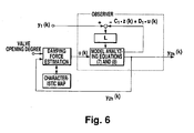
- a state observer for the system for estimating the relative velocity is defined by the following equations (7) and (8).
- z(k) denotes an estimated value of the parameter x(k) computed by the defined state observer.
- y 2h (k) denotes an estimated value of a relative velocity y 2 (k).
- Fig. 6 shows a block diagram of the observer defined by the equations (7) and (8).
- L in the equation (7) denotes the gain of a stationary Kalman filter, which can be obtained from the following equations (9) and (10).
- P [ ( APA T + BVB T ⁇ ) - 1 + C T ⁇ W - 1 ⁇ C ] - 1
- L PC 1 T ⁇ W - 1
- V and W are design parameters which can be set by a designer in order to improve the estimation accuracy.
- a symbol P denotes the only positive constant value matrix meeting the equation (9).
- the coefficient matrixes A, B, C 1 , C 2 , D 1 and D 2 can be obtained from the constants such as the spring constant, sprung mass, and unsprung mass of the system shown in Fig. 2.
- the vertical acceleration y 1 (k) of a sprung structure can be computed in accordance with the output of an acceleration sensor provided on the sprung structure.
- an acceleration sensor for a sprung structure and directly use the acceleration detected by the sensor as the vertical acceleration y 1 (k).
- three acceleration sensors 60 are arranged so that they are not located on the same straight line and the attitude of a chassis (sprung structure) is obtained from an acceleration at the setting point to perform correction in accordance with the distances between the acceleration sensor and shock absorber attachment points and the center of gravity of the chassis.
- the chassis performs a heaving motion in which all part of the chassis move vertically in parallel.
- the detected value can directly be used as the vertical acceleration y 1 (k).
- the chassis includes a pitching motion.
- a damping force u(k) is estimated from the valve opening degree of a shock absorber and the output y 2h (k) of a state observer, that is to say, the estimated relative velocity between sprung and unsprung structures.
- the valve opening degree uses a valve opening degree command sent from the control unit 58 to each shock absorber 56. Therefore, it is unnecessary to measure an actual valve opening degree, and thus it is unnecessary to use a sensor or the like.
- the relative velocity between sprung and unsprung structures uses the data one control cycle before. When a control cycle is much smaller than the change of the relative velocity between sprung and unsprung structures, it is estimated that the difference between the data one control cycle before and the present actual relative velocity is very small.
- the damping force characteristic of a shock absorber is previously measured by using a stroke velocity and a valve opening degree as parameters and stored in the form of characteristic map data as shown in Fig. 5.
- a valve opening degree and a stroke velocity are known, it is possible to estimate the damping force u(k) of a shock absorber at that time from the characteristic map data.
- the valve opening degree is known from the valve opening degree command and the stroke velocity equals the relative velocity between sprung and unsprung structures, it is possible to estimate the damping force at that time from these pieces of data. Strictly speaking, the estimated damping force is the damping force one control cycle before.
- the relative velocity y 2h (k) is estimated by using the above described vertical acceleration y 1 (k) of a sprung structure and the damping force u(k) in accordance with the equations (7) and (8).
- Fig. 7 shows estimated relative velocity (continuous line) and actual relative velocity (broken line) between sprung and unsprung structures of a vehicle to which the apparatus of this embodiment is applied when vibrating the vehicle only in the heaving direction.
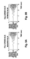
- Figs. 9A, 9B, 10A and 10B show the results of trial computation of the vibration when using a shock absorber having the damping force characteristics shown in Fig. 8 for the single-wheel model with 2 degrees of freedom shown in Fig. 2.
- an observer gain is computed at a damping coefficient of 1,000 N ⁇ s/m by using a Kalman filter theory.
- vibration is executed by sine waves with a frequency of 0.5 to 5 Hz and an amplitude of 10 mm.
- Fig. 9A shows the relative velocity between sprung and unsprung structures actually measured at a valve opening degree of 100%.
- Fig. 9B shows an estimated value under the same condition.
- Fig. 9A shows the relative velocity between sprung and unsprung structures actually measured at a valve opening degree of 100%.
- Fig. 9B shows an estimated value under the same condition.
- Fig. 10A shows a measured value when the valve opening degree is fixed to an intermediate stage
- Fig. 10B shows an estimated value under the same condition.
- the damping coefficient at a valve opening degree of 100% depends on the stroke velocity, it approximately ranges between 1,000 and 2,800 N ⁇ s/m.
- the damping coefficient at the intermediate stage of the valve opening degree approximately ranges between 1,700 and 18,000 N ⁇ s/m.
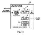
- Fig. 11 shows a relative velocity estimating section 12B which is another example structure of the relative velocity estimating section 12 shown in Fig. 3 which does not form part of the present invention.
- a damping-coefficient estimating section 28 estimates a damping coefficient based on the previously-stored damping force characteristics in accordance with the relative velocity between sprung and unsprung structures estimated in a previous control cycle, preferably the last control cycle.
- a deviation computing section 30 computes the deviation of the vertical acceleration of the sprung structure computed by the acceleration computing section 10 from the estimated vertical acceleration of the sprung structure.
- An amplifying section 32 amplifies the deviation at a predetermined rate corresponding to the damping coefficient estimated by the damping-coefficient estimating section 28.
- a vibration characteristic storing section 34 previously stores vibration characteristics of the vehicle. The vibration characteristics include a sprung mass, unsprung mass, and spring constant and are stored as vibration models in accordance with these constants.
- An analyzing section 36 computes the acceleration of a sprung structure and the relative velocity between sprung and unsprung structures in accordance with the amplified acceleration deviation and the stored vibration models. In this case, the computed acceleration is used for operations by the deviation computing section 30.
- the relative velocity estimating section 12B is a part of the control unit 58.
- the vibration characteristic storing section 34 is a ROM provided for the control unit 58.
- the deviation computing section 30, amplifying section 32, and analyzing section 36 use a CPU to be operated by a predetermined program and a circuit element for performing predetermined operations.
- an output equation for computing a relative velocity y 2 from a parameter is defined as the following equation (13).
- y 2 C c ⁇ 2 ⁇ x c
- y 2 Zw ′ - Zu ′
- C c2 is a coefficient matrix.
- a damping force f c is shown by the following equation (14).
- Cs(Zs', ar) denotes that the damping coefficient Cs is a value determined by a relative velocity Zs and a valve opening degree ar. Moreover, it is assumed that the minimum value of the damping coefficient Cs is Cs min and the maximum value is Cs max .
- a V (q) and C V1 (q) are assumed as A Vmin and C V1min , respectively.
- a vmax A c + Cs max ⁇ BcN
- x ch denotes an estimated signal of a parameter x c of a system to be computed by the defined state observer.
- y 2h denotes an estimated signal of a relative velocity y 2 .
- Figs. 12A, 12B, 13A and 13B show the results of trial computation of the relative velocity between sprung and unsprung structures of the single-wheel model with two degrees of freedom shown in Fig. 2 by using the above state observers.
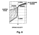
- Fig. 8 shows the damping characteristics of a shock absorber.
- Figs. 12A, 12B, 13A and 13B show trial computation results when computing the observer gain L(q) in accordance with the damping coefficient Cs.
- the observer gain L(q) is computed by using the stationary Kalman filter theory at damping coefficients of 1,000 N ⁇ s/m and 65,600 N ⁇ s/m.
- Figs. 12A and 12B show the case of a valve opening degree of 100%
- Figs. 13A and 13B show the case of fixing a valve opening degree to an intermediate stage.
- Figs. 12A and 13A show measured values
- Figs. 12B and 13B show estimated values.
- the damping coefficients in the case of Figs. 12A and 12B show approx.
- Fig. 14 shows a relative velocity estimating section 12c according to the present invention which is a structure of the relative velocity estimating section 12 sown in Fig. 3.
- a deviation computing section 20 first computes the deviation of the vertical acceleration of a sprung structure computed by the acceleration computing section 10 from the estimated vertical acceleration of the sprung structure.
- a deviation amplifying section 22 amplifies the deviation at a predetermined rate corresponding to the above valve opening degree instruction.
- the vibration characteristics of the vehicle are previously stored in a vibration characteristic storing section 24.
- the vibration characteristics include a sprung mass, unsprung mass, and spring constant and are stored as vibration models in accordance with these constants.
- An analyzing section 26 computes the acceleration of a sprung structure and the relative velocity between sprung and unsprung structures in accordance with the amplified acceleration deviation and the stored vibration models. In this case, the computed acceleration is used for operations by the deviation computing section 20.
- the relative velocity estimating section 12C is a part of the control unit 58.
- the vibration characteristic storing section 24 is a ROM provided for the control unit 58.
- the deviation computing section 20, amplifying section 22, and analyzing section 36 use a CPU to be operated by a predetermined program and a circuit element for performing predetermined operations.
- the relative velocity estimating section 12C computes an observer gain L(p) in accordance with only the valve opening degree command ar.
- the observer gain L(p) is computed in accordance with the following equations (22) and (23).
- ar min denotes a valve opening degree command when fully opening a valve
- ar max denotes a valve opening degree command when fully closing the valve
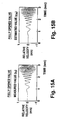
- Figs. 15A, 15B, 16A and 16B show the results of trial computation of the relative velocity between sprung and unsprung structures of the single-wheel model with two degrees of freedom shown in Fig. 2 by using the above observers.
- the damping characteristics of a shock absorber are shown in Fig. 8.
- Figs. 15A, 15B, 16A and 16B show the results of trial computation the observer gain L(p) in accordance with the valve opening degree command ar.
- the observer gain L(p) is computed at damping coefficients of 1,000 N ⁇ s/m and 65,600 N ⁇ s/m by using the stationary Kalman filter theory.
- Figs. 15A and 15B show the case of a valve opening degree of 100%
- Figs. 16A and 16B show the case of fixing the valve opening degree to an intermediate stage.
- Figs. 15A and 16A show measured values
- Figs. 15B and 16B show estimated values.
- the damping coefficients in the case of Figs. 15A and 15B show approx.
- Figs. 17 and 18 the results of vibration tests on the actual vehicle shown in Fig. 1 in its heaving direction are shown by continuous lines.
- an observer gain is L(q) of the equation (21) computed in accordance with a damping coefficient and computed at damping coefficients of 1,000 N ⁇ s/m and 65,600 N ⁇ s/m by using the stationary Kalman filter theory.
- Fig. 17 shows the case of a valve opening degree of 100%
- Fig. 18 shows the case of a valve opening degree of 0%.
- the damping coefficient reaches approx. 1,000 to 2,800 N ⁇ s/m in the case of a valve opening degree of 100% and 65,600 N ⁇ s/m at most in the case of a valve opening degree of 0%.
- Figs. 17 and 18 denote the values obtained by differentiating the outputs of vehicle height sensors and show actual relative velocities between sprung and unsprung structures. From Figs. 17 and 18, it is found that a preferable estimation result can be obtained even if a damping coefficient varies greatly.
- Each of the above examples estimates a damping force from the information on valve opening degree or the relative velocity between sprung and unsprung structures computed in accordance with the information for valve opening degree and in a previous control cycle. Therefore, a high estimation accuracy is obtained. Moreover, by estimating the above relative velocity in accordance with an estimated value of the above damping force, a more-accurate relative velocity can be obtained.
Landscapes
- Engineering & Computer Science (AREA)
- Mechanical Engineering (AREA)
- Vehicle Body Suspensions (AREA)
Claims (3)
- Federungssteuervorrichtung zwischen einer abgefederten Struktur (50) und einer nicht abgefederten Struktur (51) eines Fahrzeugs, wobei die abgefederte Struktur und die nicht abgefederte Struktur über eine Feder (54a-54d) und einen Stoßdämpfer (56a-56d) mit der Fähigkeit, durch Anpassen des Ventilöffnungsgrads eines Fluidkanals die Dämpfkräfte zu variieren, verbunden sind, wobei die Vorrichtung umfasst:- Beschleunigungsberechnungsmittel (10) zum Berechnen der vertikalen Beschleunigung der Federstruktur;- Relativ-Geschwindigkeits-Schätzmittel (12), umfassend:Eingaben für die berechnete Beschleunigung und für einen Ventilöffnungsgrad-Befehlswert zum Anpassen des Ventilöffnungsgrads,wobei die Relativ-Geschwindigkeits-Schätzmittel dazu ausgelegt sind, die Relativ-Geschwindigkeit zwischen der gefederten Struktur (50) und der nicht gefederten Struktur (51) in Übereinstimmung mit der eingegebenen berechneten Beschleunigung und dem eingegebenen Ventilöffnungsgrad-Befehlswert zu schätzen,wobei die Relativ-Geschwindigkeits-Schätzmittel (12C) versehen sind mit- Vibrationskennlinienspeichermittel (24) zum vorherigen Speichern der Vibrationskennlinie des Fahrzeugs,- Abweichungsberechnungsmittel (20) zum Berechnen der Abweichung der detektierten Beschleunigung von einer geschätzten vertikalen Beschleunigung einer gefederten Struktur,- Verstärkungsmittel (22) zum Verstärken der Abweichung in Übereinstimmung nur mit dem Ventilöfnungsgrad-Befehlswert; und- Vibrationsanalysationsmittel (26) zum Schätzen der vertikalen Beschleunigung der gefederten Struktur und der relativen Geschwindigkeit zwischen gefederten und nicht gefederten Struktur.
- Federungssteuervorrichtung zwischen einer gefederten Struktur und einer nicht gefederten Struktur nach Anspruch 1, wobei es sich bei den Beschleunigungsberechnungsmitteln um einen Beschleunigungssensor (60a-60c) zum Detektieren der Beschleunigung eines Aufhängungspunkts des Stoßdämpfers der gefederten Struktur handelt.
- Federungssteuervorrichtung zwischen einer gefederten Struktur und einer nicht gefederten Struktur nach Anspruch 1, wobei die Beschleunigungsberechnungsmittel eine Vielzahl von Beschleunigungssensoren (60a-60c), die für eine gefederte Struktur (50) bereitgestellt sind, und Aufhängungspunkt-Beschleunigungs-Berechnungsmittel zur Berechnung der Beschleunigung mindestens eines Aufhängungspunkts des Stoßdämpfers der gefederten Struktur in Übereinstimmung mit der durch die Beschleunigungssensoren detektierten Beschleunigung, aufweist.
Applications Claiming Priority (3)
| Application Number | Priority Date | Filing Date | Title |
|---|---|---|---|
| JP12756296 | 1996-05-22 | ||
| JP08127562A JP3118414B2 (ja) | 1996-05-22 | 1996-05-22 | 車両のばね上ばね下相対速度算出装置 |
| EP97401117A EP0808734B1 (de) | 1996-05-22 | 1997-05-21 | Radaufhängung-Regelungsgerät mit einem Rechengerät für die relative Geschwindigkeit zwischen gefederter und nicht gefederter Struktur eines Fahrzeuges. |
Related Parent Applications (1)
| Application Number | Title | Priority Date | Filing Date |
|---|---|---|---|
| EP97401117A Division EP0808734B1 (de) | 1996-05-22 | 1997-05-21 | Radaufhängung-Regelungsgerät mit einem Rechengerät für die relative Geschwindigkeit zwischen gefederter und nicht gefederter Struktur eines Fahrzeuges. |
Publications (2)
| Publication Number | Publication Date |
|---|---|
| EP1477342A1 EP1477342A1 (de) | 2004-11-17 |
| EP1477342B1 true EP1477342B1 (de) | 2007-07-25 |
Family
ID=14963106
Family Applications (2)
| Application Number | Title | Priority Date | Filing Date |
|---|---|---|---|
| EP97401117A Expired - Lifetime EP0808734B1 (de) | 1996-05-22 | 1997-05-21 | Radaufhängung-Regelungsgerät mit einem Rechengerät für die relative Geschwindigkeit zwischen gefederter und nicht gefederter Struktur eines Fahrzeuges. |
| EP04018982A Expired - Lifetime EP1477342B1 (de) | 1996-05-22 | 1997-05-21 | Rechengerät für die relative Geschwindigkeit zwischen gefederter und nicht gefederter Struktur eines Fahrzeuges. |
Family Applications Before (1)
| Application Number | Title | Priority Date | Filing Date |
|---|---|---|---|
| EP97401117A Expired - Lifetime EP0808734B1 (de) | 1996-05-22 | 1997-05-21 | Radaufhängung-Regelungsgerät mit einem Rechengerät für die relative Geschwindigkeit zwischen gefederter und nicht gefederter Struktur eines Fahrzeuges. |
Country Status (4)
| Country | Link |
|---|---|
| US (1) | US5987368A (de) |
| EP (2) | EP0808734B1 (de) |
| JP (1) | JP3118414B2 (de) |
| DE (2) | DE69737958T2 (de) |
Families Citing this family (50)
| Publication number | Priority date | Publication date | Assignee | Title |
|---|---|---|---|---|
| JPH0552615U (ja) * | 1991-12-10 | 1993-07-13 | 日本製箔株式会社 | ガスレンジ用アルミシート製マット |
| JPH11170837A (ja) * | 1997-12-16 | 1999-06-29 | Toyota Motor Corp | 車高調整装置 |
| JP2000006632A (ja) * | 1998-06-25 | 2000-01-11 | Isuzu Motors Ltd | 車両の懸架機構の制御装置 |
| JP3424591B2 (ja) * | 1999-04-06 | 2003-07-07 | トヨタ自動車株式会社 | 車両の運動状態量推定装置 |
| KR100451288B1 (ko) * | 2000-08-31 | 2004-10-06 | 도키코 가부시키 가이샤 | 서스펜션 제어장치 |
| DE10126933B4 (de) * | 2001-06-01 | 2004-08-26 | Continental Aktiengesellschaft | Verfahren zur Regelung oder Steuerung der Dämpferkraft verstellbarer Dämpfer an Fahrzeugen |
| KR100550070B1 (ko) * | 2003-11-26 | 2006-02-08 | 주식회사 만도 | 전자 제어 현가 장치와 이를 이용한 댐퍼 감쇠력 제어 방법 |
| JP4546307B2 (ja) * | 2005-03-30 | 2010-09-15 | 本田技研工業株式会社 | 可変減衰力ダンパーの制御装置 |
| JP4199273B2 (ja) * | 2006-08-29 | 2008-12-17 | 本田技研工業株式会社 | 車両状態推定装置 |
| WO2008138067A1 (en) * | 2007-05-15 | 2008-11-20 | University Of Technology, Sydney | A method and system for estimating parameters of a vehicle |
| FR2916409B1 (fr) * | 2007-05-25 | 2009-08-21 | Snr Roulements Sa | Procede d'estimation d'un parametre de roulage d'un vehicule automobile au moyen d'un filtre de kalman |
| JP4930346B2 (ja) * | 2007-11-29 | 2012-05-16 | トヨタ自動車株式会社 | サスペンションシステム |
| US8839920B2 (en) | 2008-04-17 | 2014-09-23 | Levant Power Corporation | Hydraulic energy transfer |
| US10060499B2 (en) | 2009-01-07 | 2018-08-28 | Fox Factory, Inc. | Method and apparatus for an adjustable damper |
| US10047817B2 (en) * | 2009-01-07 | 2018-08-14 | Fox Factory, Inc. | Method and apparatus for an adjustable damper |
| US9452654B2 (en) | 2009-01-07 | 2016-09-27 | Fox Factory, Inc. | Method and apparatus for an adjustable damper |
| US20100170760A1 (en) | 2009-01-07 | 2010-07-08 | John Marking | Remotely Operated Bypass for a Suspension Damper |
| US11306798B2 (en) | 2008-05-09 | 2022-04-19 | Fox Factory, Inc. | Position sensitive suspension damping with an active valve |
| US20120305350A1 (en) | 2011-05-31 | 2012-12-06 | Ericksen Everet O | Methods and apparatus for position sensitive suspension damping |
| US8627932B2 (en) | 2009-01-07 | 2014-01-14 | Fox Factory, Inc. | Bypass for a suspension damper |
| JP5168567B2 (ja) * | 2008-09-01 | 2013-03-21 | 日立オートモティブシステムズ株式会社 | 状態推定装置、サスペンション制御装置及びサスペンションシステム |
| US12491961B2 (en) | 2008-11-25 | 2025-12-09 | Fox Factory, Inc. | Seat post |
| US10036443B2 (en) | 2009-03-19 | 2018-07-31 | Fox Factory, Inc. | Methods and apparatus for suspension adjustment |
| US9140325B2 (en) | 2009-03-19 | 2015-09-22 | Fox Factory, Inc. | Methods and apparatus for selective spring pre-load adjustment |
| US11299233B2 (en) | 2009-01-07 | 2022-04-12 | Fox Factory, Inc. | Method and apparatus for an adjustable damper |
| US9038791B2 (en) | 2009-01-07 | 2015-05-26 | Fox Factory, Inc. | Compression isolator for a suspension damper |
| US12122205B2 (en) | 2009-01-07 | 2024-10-22 | Fox Factory, Inc. | Active valve for an internal bypass |
| EP2312180B1 (de) | 2009-10-13 | 2019-09-18 | Fox Factory, Inc. | Vorrichtung zur Steuerung eines hydraulischen Dämpfers |
| US10697514B2 (en) | 2010-01-20 | 2020-06-30 | Fox Factory, Inc. | Remotely operated bypass for a suspension damper |
| EP2582976B1 (de) | 2010-06-16 | 2019-08-21 | ClearMotion, Inc. | Integrierter stromerzeugender dämpfer |
| EP3567272B1 (de) | 2011-09-12 | 2021-05-26 | Fox Factory, Inc. | Verfahren und vorrichtung zur aufhängungseinstellung |
| US11279199B2 (en) | 2012-01-25 | 2022-03-22 | Fox Factory, Inc. | Suspension damper with by-pass valves |
| US10330171B2 (en) | 2012-05-10 | 2019-06-25 | Fox Factory, Inc. | Method and apparatus for an adjustable damper |
| CN104302492B (zh) * | 2012-05-14 | 2016-08-24 | 日产自动车株式会社 | 车辆的控制装置和车辆的控制方法 |
| JP6059564B2 (ja) * | 2013-03-13 | 2017-01-11 | Kyb株式会社 | ダンパ速度検知装置 |
| US9809078B2 (en) * | 2013-03-15 | 2017-11-07 | ClearMotion, Inc. | Multi-path fluid diverter valve |
| US9702349B2 (en) | 2013-03-15 | 2017-07-11 | ClearMotion, Inc. | Active vehicle suspension system |
| EP4450845A3 (de) | 2013-03-15 | 2025-01-01 | ClearMotion, Inc. | Verbesserungen an einer aktiven fahrzeugaufhängung |
| US9174508B2 (en) | 2013-03-15 | 2015-11-03 | Levant Power Corporation | Active vehicle suspension |
| EP3825156A1 (de) | 2013-04-23 | 2021-05-26 | ClearMotion, Inc. | Aktive aufhängung mit strukturellem aktuator |
| US9702424B2 (en) | 2014-10-06 | 2017-07-11 | ClearMotion, Inc. | Hydraulic damper, hydraulic bump-stop and diverter valve |
| JP2017008659A (ja) * | 2015-06-25 | 2017-01-12 | Kyb株式会社 | Zmp演算装置およびzmp演算方法 |
| US10737546B2 (en) | 2016-04-08 | 2020-08-11 | Fox Factory, Inc. | Electronic compression and rebound control |
| JP2018058463A (ja) * | 2016-10-04 | 2018-04-12 | アイシン精機株式会社 | 減衰力制御装置 |
| JP6822338B2 (ja) * | 2017-07-19 | 2021-01-27 | トヨタ自動車株式会社 | サスペンション制御システム |
| JP6923591B2 (ja) * | 2019-04-12 | 2021-08-18 | 本田技研工業株式会社 | 電動サスペンション装置 |
| JP7327345B2 (ja) | 2020-10-16 | 2023-08-16 | トヨタ自動車株式会社 | サスペンションストローク関連値推定装置及び方法 |
| CN112572086A (zh) * | 2020-12-22 | 2021-03-30 | 华为技术有限公司 | 车辆、车辆悬架的控制方法及其相关设备 |
| DE102023115400B3 (de) | 2023-06-13 | 2024-06-27 | Dr. Ing. H.C. F. Porsche Aktiengesellschaft | Dämpfungssystem für ein Rad eines Kraftfahrzeugs und Kraftfahrzeug |
| CN121234630B (zh) * | 2025-12-02 | 2026-04-21 | 重庆蓝电汽车科技有限公司 | 悬架阻尼力估计方法、装置、设备、存储介质和程序产品 |
Family Cites Families (10)
| Publication number | Priority date | Publication date | Assignee | Title |
|---|---|---|---|---|
| EP0264944B1 (de) * | 1986-10-24 | 1993-01-13 | Mazda Motor Corporation | Fahrzeugaufhängungssystem mit veränderlichen Aufhängungscharakteristiken |
| US5434782A (en) * | 1991-05-20 | 1995-07-18 | General Motors Corporation | Suspension system state observer |
| US5235512A (en) * | 1991-06-24 | 1993-08-10 | Ford Motor Company | Self-tuning speed control for a vehicle |
| JP3080266B2 (ja) * | 1992-05-21 | 2000-08-21 | 株式会社ユニシアジェックス | 車両懸架装置 |
| DE4218087C2 (de) * | 1992-06-01 | 2001-03-22 | Rolf Isermann | Verfahren zur Ermittlung des Dämpfungskoeffizienten einer Radaufhängung eines Kraftfahrzeuges |
| US5425436A (en) * | 1992-08-26 | 1995-06-20 | Nippondenso Co., Ltd. | Automotive suspension control system utilizing variable damping force shock absorber |
| JP3131048B2 (ja) * | 1992-09-30 | 2001-01-31 | マツダ株式会社 | 車両のサスペンション装置 |
| JP3182021B2 (ja) * | 1993-03-22 | 2001-07-03 | 株式会社ユニシアジェックス | 車両懸架装置 |
| EP0659598A1 (de) * | 1993-12-21 | 1995-06-28 | Unisia Jecs Corporation | Vorrichtung und Verfahren zum Regeln der Dämpfungscharakteristiken von Fahrzeugstossdämpfern |
| JP3374208B2 (ja) * | 1995-07-06 | 2003-02-04 | 株式会社日立ユニシアオートモティブ | 車両懸架装置 |
-
1996
- 1996-05-22 JP JP08127562A patent/JP3118414B2/ja not_active Expired - Lifetime
-
1997
- 1997-05-21 US US08/861,051 patent/US5987368A/en not_active Expired - Lifetime
- 1997-05-21 DE DE69737958T patent/DE69737958T2/de not_active Expired - Lifetime
- 1997-05-21 EP EP97401117A patent/EP0808734B1/de not_active Expired - Lifetime
- 1997-05-21 EP EP04018982A patent/EP1477342B1/de not_active Expired - Lifetime
- 1997-05-21 DE DE69731423T patent/DE69731423T2/de not_active Expired - Lifetime
Also Published As
| Publication number | Publication date |
|---|---|
| EP1477342A1 (de) | 2004-11-17 |
| DE69731423T2 (de) | 2005-10-27 |
| EP0808734A2 (de) | 1997-11-26 |
| US5987368A (en) | 1999-11-16 |
| EP0808734A3 (de) | 1999-07-21 |
| DE69731423D1 (de) | 2004-12-09 |
| DE69737958D1 (de) | 2007-09-06 |
| JPH09309315A (ja) | 1997-12-02 |
| DE69737958T2 (de) | 2008-04-10 |
| JP3118414B2 (ja) | 2000-12-18 |
| EP0808734B1 (de) | 2004-11-03 |
Similar Documents
| Publication | Publication Date | Title |
|---|---|---|
| EP0808734B1 (de) | Radaufhängung-Regelungsgerät mit einem Rechengerät für die relative Geschwindigkeit zwischen gefederter und nicht gefederter Struktur eines Fahrzeuges. | |
| US5987367A (en) | Vehicle sprung- and unsprung-structure relative-velocity computing apparatus | |
| US5475593A (en) | Distributed active vehicle suspension system | |
| US6366841B1 (en) | Damping force control device and method | |
| EP0672549B1 (de) | Verfahren und Vorrichtung für die Steuerung einer aktiven Radaufhängung | |
| US5550739A (en) | Semi-active suspension control system | |
| US3995883A (en) | Land vehicle wheel suspension arrangements | |
| US6684140B2 (en) | System for sensing vehicle global and relative attitudes using suspension height sensors | |
| US5373445A (en) | Method and apparatus for determining dynamic force within an air spring suspension | |
| US8116938B2 (en) | Vehicle state estimating apparatus, suspension control apparatus and suspension system | |
| US8428807B2 (en) | Method for determining at least one displacement state of a vehicle body | |
| EP0901082A2 (de) | Verfahren und Gerät zur dynamischen Niveauregulierung | |
| EP0470993B1 (de) | Steuersystem für die aufhängung eines landfahrzeugs | |
| JP3424591B2 (ja) | 車両の運動状態量推定装置 | |
| US8523192B2 (en) | Method and system for operating a motor vehicle | |
| US20030125857A1 (en) | Continuously variable semi-active suspension system using centrally located yaw rate and accelerometer sensors | |
| JPH071940A (ja) | 適応形サスペンションシステム | |
| Esmailzadeh et al. | Optimal adaptive active suspensions for a full car model | |
| US12269309B2 (en) | Suspension stroke related value estimation device and method | |
| US5563789A (en) | System to generate signals for control or regulation of a controllable or regulable chassis | |
| US5086656A (en) | Method and apparatus for calculating the axle load of a vehicle | |
| US7571030B2 (en) | Estimation of vehicle roll rate and roll angle using suspension deflection sensors | |
| CN108595817A (zh) | 一种基于观测器的半主动悬架汽车侧倾参数在线估计方法 | |
| JP2019031125A (ja) | サスペンション制御システム | |
| JP2008030536A (ja) | 車両状態量検出装置 |
Legal Events
| Date | Code | Title | Description |
|---|---|---|---|
| PUAI | Public reference made under article 153(3) epc to a published international application that has entered the european phase |
Free format text: ORIGINAL CODE: 0009012 |
|
| AC | Divisional application: reference to earlier application |
Ref document number: 0808734 Country of ref document: EP Kind code of ref document: P |
|
| AK | Designated contracting states |
Kind code of ref document: A1 Designated state(s): DE FR GB |
|
| 17P | Request for examination filed |
Effective date: 20050517 |
|
| AKX | Designation fees paid |
Designated state(s): DE FR GB |
|
| GRAP | Despatch of communication of intention to grant a patent |
Free format text: ORIGINAL CODE: EPIDOSNIGR1 |
|
| GRAS | Grant fee paid |
Free format text: ORIGINAL CODE: EPIDOSNIGR3 |
|
| GRAA | (expected) grant |
Free format text: ORIGINAL CODE: 0009210 |
|
| AC | Divisional application: reference to earlier application |
Ref document number: 0808734 Country of ref document: EP Kind code of ref document: P |
|
| AK | Designated contracting states |
Kind code of ref document: B1 Designated state(s): DE FR GB |
|
| REG | Reference to a national code |
Ref country code: GB Ref legal event code: FG4D |
|
| REF | Corresponds to: |
Ref document number: 69737958 Country of ref document: DE Date of ref document: 20070906 Kind code of ref document: P |
|
| ET | Fr: translation filed | ||
| PLBE | No opposition filed within time limit |
Free format text: ORIGINAL CODE: 0009261 |
|
| STAA | Information on the status of an ep patent application or granted ep patent |
Free format text: STATUS: NO OPPOSITION FILED WITHIN TIME LIMIT |
|
| 26N | No opposition filed |
Effective date: 20080428 |
|
| REG | Reference to a national code |
Ref country code: GB Ref legal event code: 746 Effective date: 20081024 |
|
| REG | Reference to a national code |
Ref country code: FR Ref legal event code: PLFP Year of fee payment: 20 |
|
| PGFP | Annual fee paid to national office [announced via postgrant information from national office to epo] |
Ref country code: DE Payment date: 20160518 Year of fee payment: 20 Ref country code: GB Payment date: 20160518 Year of fee payment: 20 |
|
| PGFP | Annual fee paid to national office [announced via postgrant information from national office to epo] |
Ref country code: FR Payment date: 20160412 Year of fee payment: 20 |
|
| REG | Reference to a national code |
Ref country code: DE Ref legal event code: R071 Ref document number: 69737958 Country of ref document: DE |
|
| REG | Reference to a national code |
Ref country code: GB Ref legal event code: PE20 Expiry date: 20170520 |
|
| PG25 | Lapsed in a contracting state [announced via postgrant information from national office to epo] |
Ref country code: GB Free format text: LAPSE BECAUSE OF EXPIRATION OF PROTECTION Effective date: 20170520 |