EP0659598A1 - Vorrichtung und Verfahren zum Regeln der Dämpfungscharakteristiken von Fahrzeugstossdämpfern - Google Patents
Vorrichtung und Verfahren zum Regeln der Dämpfungscharakteristiken von Fahrzeugstossdämpfern Download PDFInfo
- Publication number
- EP0659598A1 EP0659598A1 EP19940120003 EP94120003A EP0659598A1 EP 0659598 A1 EP0659598 A1 EP 0659598A1 EP 19940120003 EP19940120003 EP 19940120003 EP 94120003 A EP94120003 A EP 94120003A EP 0659598 A1 EP0659598 A1 EP 0659598A1
- Authority
- EP
- European Patent Office
- Prior art keywords
- road wheel
- vehicular
- wheel side
- signal
- damping force
- Prior art date
- Legal status (The legal status is an assumption and is not a legal conclusion. Google has not performed a legal analysis and makes no representation as to the accuracy of the status listed.)
- Withdrawn
Links
- 238000013016 damping Methods 0.000 title claims abstract description 141
- 239000006096 absorbing agent Substances 0.000 title claims abstract description 121
- 230000035939 shock Effects 0.000 title claims abstract description 121
- 238000000034 method Methods 0.000 title claims abstract description 10
- 230000001419 dependent effect Effects 0.000 claims abstract description 8
- 230000001133 acceleration Effects 0.000 claims description 96
- 230000015572 biosynthetic process Effects 0.000 claims description 17
- 238000003786 synthesis reaction Methods 0.000 claims description 17
- 230000003111 delayed effect Effects 0.000 claims description 10
- 230000002194 synthesizing effect Effects 0.000 claims description 7
- 230000008859 change Effects 0.000 claims description 4
- 230000007423 decrease Effects 0.000 claims description 3
- FGUUSXIOTUKUDN-IBGZPJMESA-N C1(=CC=CC=C1)N1C2=C(NC([C@H](C1)NC=1OC(=NN=1)C1=CC=CC=C1)=O)C=CC=C2 Chemical compound C1(=CC=CC=C1)N1C2=C(NC([C@H](C1)NC=1OC(=NN=1)C1=CC=CC=C1)=O)C=CC=C2 FGUUSXIOTUKUDN-IBGZPJMESA-N 0.000 claims 1
- 230000003247 decreasing effect Effects 0.000 claims 1
- 230000006835 compression Effects 0.000 description 36
- 238000007906 compression Methods 0.000 description 36
- 230000006399 behavior Effects 0.000 description 29
- 238000012545 processing Methods 0.000 description 20
- 238000005096 rolling process Methods 0.000 description 20
- 238000010586 diagram Methods 0.000 description 13
- 239000012530 fluid Substances 0.000 description 11
- 238000006243 chemical reaction Methods 0.000 description 8
- 230000001747 exhibiting effect Effects 0.000 description 5
- 230000008030 elimination Effects 0.000 description 4
- 238000003379 elimination reaction Methods 0.000 description 4
- 230000000149 penetrating effect Effects 0.000 description 4
- 230000002093 peripheral effect Effects 0.000 description 4
- 239000000725 suspension Substances 0.000 description 4
- 238000004891 communication Methods 0.000 description 3
- 238000012937 correction Methods 0.000 description 3
- 238000009795 derivation Methods 0.000 description 3
- 230000009467 reduction Effects 0.000 description 3
- 101100381996 Saccharomyces cerevisiae (strain ATCC 204508 / S288c) BRO1 gene Proteins 0.000 description 2
- 238000006073 displacement reaction Methods 0.000 description 2
- 238000001914 filtration Methods 0.000 description 2
- 230000005484 gravity Effects 0.000 description 2
- 238000012986 modification Methods 0.000 description 2
- 230000004048 modification Effects 0.000 description 2
- 230000004044 response Effects 0.000 description 2
- 238000012360 testing method Methods 0.000 description 2
- 241000289619 Macropodidae Species 0.000 description 1
- 230000009471 action Effects 0.000 description 1
- 238000013459 approach Methods 0.000 description 1
- 230000000712 assembly Effects 0.000 description 1
- 238000000429 assembly Methods 0.000 description 1
- 238000010276 construction Methods 0.000 description 1
- 238000001514 detection method Methods 0.000 description 1
- 230000000694 effects Effects 0.000 description 1
- 230000001629 suppression Effects 0.000 description 1
- 238000002834 transmittance Methods 0.000 description 1
Images














Classifications
-
- F—MECHANICAL ENGINEERING; LIGHTING; HEATING; WEAPONS; BLASTING
- F16—ENGINEERING ELEMENTS AND UNITS; GENERAL MEASURES FOR PRODUCING AND MAINTAINING EFFECTIVE FUNCTIONING OF MACHINES OR INSTALLATIONS; THERMAL INSULATION IN GENERAL
- F16F—SPRINGS; SHOCK-ABSORBERS; MEANS FOR DAMPING VIBRATION
- F16F9/00—Springs, vibration-dampers, shock-absorbers, or similarly-constructed movement-dampers using a fluid or the equivalent as damping medium
- F16F9/32—Details
- F16F9/44—Means on or in the damper for manual or non-automatic adjustment; such means combined with temperature correction
- F16F9/46—Means on or in the damper for manual or non-automatic adjustment; such means combined with temperature correction allowing control from a distance, i.e. location of means for control input being remote from site of valves, e.g. on damper external wall
- F16F9/466—Throttling control, i.e. regulation of flow passage geometry
- F16F9/467—Throttling control, i.e. regulation of flow passage geometry using rotary valves
- F16F9/468—Throttling control, i.e. regulation of flow passage geometry using rotary valves controlling at least one bypass to main flow path
-
- B—PERFORMING OPERATIONS; TRANSPORTING
- B60—VEHICLES IN GENERAL
- B60G—VEHICLE SUSPENSION ARRANGEMENTS
- B60G17/00—Resilient suspensions having means for adjusting the spring or vibration-damper characteristics, for regulating the distance between a supporting surface and a sprung part of vehicle or for locking suspension during use to meet varying vehicular or surface conditions, e.g. due to speed or load
- B60G17/015—Resilient suspensions having means for adjusting the spring or vibration-damper characteristics, for regulating the distance between a supporting surface and a sprung part of vehicle or for locking suspension during use to meet varying vehicular or surface conditions, e.g. due to speed or load the regulating means comprising electric or electronic elements
-
- B—PERFORMING OPERATIONS; TRANSPORTING
- B60—VEHICLES IN GENERAL
- B60G—VEHICLE SUSPENSION ARRANGEMENTS
- B60G17/00—Resilient suspensions having means for adjusting the spring or vibration-damper characteristics, for regulating the distance between a supporting surface and a sprung part of vehicle or for locking suspension during use to meet varying vehicular or surface conditions, e.g. due to speed or load
- B60G17/015—Resilient suspensions having means for adjusting the spring or vibration-damper characteristics, for regulating the distance between a supporting surface and a sprung part of vehicle or for locking suspension during use to meet varying vehicular or surface conditions, e.g. due to speed or load the regulating means comprising electric or electronic elements
- B60G17/016—Resilient suspensions having means for adjusting the spring or vibration-damper characteristics, for regulating the distance between a supporting surface and a sprung part of vehicle or for locking suspension during use to meet varying vehicular or surface conditions, e.g. due to speed or load the regulating means comprising electric or electronic elements characterised by their responsiveness, when the vehicle is travelling, to specific motion, a specific condition, or driver input
- B60G17/0165—Resilient suspensions having means for adjusting the spring or vibration-damper characteristics, for regulating the distance between a supporting surface and a sprung part of vehicle or for locking suspension during use to meet varying vehicular or surface conditions, e.g. due to speed or load the regulating means comprising electric or electronic elements characterised by their responsiveness, when the vehicle is travelling, to specific motion, a specific condition, or driver input to an external condition, e.g. rough road surface, side wind
-
- B—PERFORMING OPERATIONS; TRANSPORTING
- B60—VEHICLES IN GENERAL
- B60G—VEHICLE SUSPENSION ARRANGEMENTS
- B60G17/00—Resilient suspensions having means for adjusting the spring or vibration-damper characteristics, for regulating the distance between a supporting surface and a sprung part of vehicle or for locking suspension during use to meet varying vehicular or surface conditions, e.g. due to speed or load
- B60G17/015—Resilient suspensions having means for adjusting the spring or vibration-damper characteristics, for regulating the distance between a supporting surface and a sprung part of vehicle or for locking suspension during use to meet varying vehicular or surface conditions, e.g. due to speed or load the regulating means comprising electric or electronic elements
- B60G17/018—Resilient suspensions having means for adjusting the spring or vibration-damper characteristics, for regulating the distance between a supporting surface and a sprung part of vehicle or for locking suspension during use to meet varying vehicular or surface conditions, e.g. due to speed or load the regulating means comprising electric or electronic elements characterised by the use of a specific signal treatment or control method
-
- B—PERFORMING OPERATIONS; TRANSPORTING
- B60—VEHICLES IN GENERAL
- B60G—VEHICLE SUSPENSION ARRANGEMENTS
- B60G2400/00—Indexing codes relating to detected, measured or calculated conditions or factors
- B60G2400/10—Acceleration; Deceleration
- B60G2400/102—Acceleration; Deceleration vertical
-
- B—PERFORMING OPERATIONS; TRANSPORTING
- B60—VEHICLES IN GENERAL
- B60G—VEHICLE SUSPENSION ARRANGEMENTS
- B60G2400/00—Indexing codes relating to detected, measured or calculated conditions or factors
- B60G2400/20—Speed
- B60G2400/202—Piston speed; Relative velocity between vehicle body and wheel
-
- B—PERFORMING OPERATIONS; TRANSPORTING
- B60—VEHICLES IN GENERAL
- B60G—VEHICLE SUSPENSION ARRANGEMENTS
- B60G2400/00—Indexing codes relating to detected, measured or calculated conditions or factors
- B60G2400/20—Speed
- B60G2400/204—Vehicle speed
-
- B—PERFORMING OPERATIONS; TRANSPORTING
- B60—VEHICLES IN GENERAL
- B60G—VEHICLE SUSPENSION ARRANGEMENTS
- B60G2400/00—Indexing codes relating to detected, measured or calculated conditions or factors
- B60G2400/20—Speed
- B60G2400/206—Body oscillation speed; Body vibration frequency
-
- B—PERFORMING OPERATIONS; TRANSPORTING
- B60—VEHICLES IN GENERAL
- B60G—VEHICLE SUSPENSION ARRANGEMENTS
- B60G2400/00—Indexing codes relating to detected, measured or calculated conditions or factors
- B60G2400/80—Exterior conditions
- B60G2400/82—Ground surface
- B60G2400/821—Uneven, rough road sensing affecting vehicle body vibration
-
- B—PERFORMING OPERATIONS; TRANSPORTING
- B60—VEHICLES IN GENERAL
- B60G—VEHICLE SUSPENSION ARRANGEMENTS
- B60G2500/00—Indexing codes relating to the regulated action or device
- B60G2500/10—Damping action or damper
-
- B—PERFORMING OPERATIONS; TRANSPORTING
- B60—VEHICLES IN GENERAL
- B60G—VEHICLE SUSPENSION ARRANGEMENTS
- B60G2600/00—Indexing codes relating to particular elements, systems or processes used on suspension systems or suspension control systems
- B60G2600/02—Retarders, delaying means, dead zones, threshold values, cut-off frequency, timer interruption
-
- B—PERFORMING OPERATIONS; TRANSPORTING
- B60—VEHICLES IN GENERAL
- B60G—VEHICLE SUSPENSION ARRANGEMENTS
- B60G2600/00—Indexing codes relating to particular elements, systems or processes used on suspension systems or suspension control systems
- B60G2600/60—Signal noise suppression; Electronic filtering means
-
- B—PERFORMING OPERATIONS; TRANSPORTING
- B60—VEHICLES IN GENERAL
- B60G—VEHICLE SUSPENSION ARRANGEMENTS
- B60G2600/00—Indexing codes relating to particular elements, systems or processes used on suspension systems or suspension control systems
- B60G2600/60—Signal noise suppression; Electronic filtering means
- B60G2600/602—Signal noise suppression; Electronic filtering means high pass
-
- B—PERFORMING OPERATIONS; TRANSPORTING
- B60—VEHICLES IN GENERAL
- B60G—VEHICLE SUSPENSION ARRANGEMENTS
- B60G2600/00—Indexing codes relating to particular elements, systems or processes used on suspension systems or suspension control systems
- B60G2600/60—Signal noise suppression; Electronic filtering means
- B60G2600/604—Signal noise suppression; Electronic filtering means low pass
-
- B—PERFORMING OPERATIONS; TRANSPORTING
- B60—VEHICLES IN GENERAL
- B60G—VEHICLE SUSPENSION ARRANGEMENTS
- B60G2800/00—Indexing codes relating to the type of movement or to the condition of the vehicle and to the end result to be achieved by the control action
- B60G2800/90—System Controller type
- B60G2800/91—Suspension Control
- B60G2800/916—Body Vibration Control
-
- Y—GENERAL TAGGING OF NEW TECHNOLOGICAL DEVELOPMENTS; GENERAL TAGGING OF CROSS-SECTIONAL TECHNOLOGIES SPANNING OVER SEVERAL SECTIONS OF THE IPC; TECHNICAL SUBJECTS COVERED BY FORMER USPC CROSS-REFERENCE ART COLLECTIONS [XRACs] AND DIGESTS
- Y10—TECHNICAL SUBJECTS COVERED BY FORMER USPC
- Y10T—TECHNICAL SUBJECTS COVERED BY FORMER US CLASSIFICATION
- Y10T137/00—Fluid handling
- Y10T137/8593—Systems
- Y10T137/87265—Dividing into parallel flow paths with recombining
- Y10T137/87378—Second valve assembly carried by first valve head
- Y10T137/87386—With rotary plug having variable restrictor
Definitions
- the present invention relates to an apparatus and method for optimally controlling damping force characteristics of four tire wheel suspension units (shock absorbers) of an automotive vehicle.
- a Japanese Patent Application First Publication No. Heisei 4-191111 published on July 9, 1992 exemplifies a previously proposed damping force characteristic control apparatus for respective shock absorbers interposed between a corresponding vehicular body (sprung mass) and tire wheel assemblies (unsprung mass).
- a plurality of actuators each interposed between the vehicle body and a rear tire (road) wheel so as to enable an increase or decrease in a suspension force (damping force characteristic) on the vehicle body with respect to the corresponding rear tire (road) wheel, a vertical acceleration sensor arranged so as to detect a vertical acceleration acted upon the vehicle body due to a vibration input from front tire wheels caused by a recess and convex formed on a road surface on which the vehicle is running, a vehicle speed sensor arranged so as to detect the vehicle speed, and control unit arranged so as to control operations of the actuators on the basis of input signals from the above-described sensors are provided in the vehicular suspension control apparatus.
- the control unit described above is so constructed as to actuate the actuators, when determining that the vehicular body vertical acceleration detected from each of the vertical acceleration sensors exceeds a predetermined value, calculates a delay duration in time for which the rear road wheels have reached to the corresponding recess and convex of the road surface which has given the sprung mass vertical acceleration which exceeds the predetermined value and actuates the actuators described above according to the magnitude of the control signal derived by inverting a signal based on the vertical sprung mass acceleration after the calculated delay duration in time has passed upon passage of the front tire (road) wheels on the recess and convex of the road surface.
- the control for the rear road wheel side shock absorbers is carried out so as to cancel the vertical acceleration acted upon the vehicle body by referring to the vertical acceleration acted upon the vehicle body derived at the time when the front road wheels have passed on the recess and convex of the road surface, when the rear road wheels pass on the same recess and convex of the road surface. Consequently, when the rear road wheels have passed on the same recess and convex on the road surface, the vibration input derived at the time when the front road wheels have passed the same recess and convex of the road surface can be reduced.
- the vertical acceleration indicative signal detected by means of the vertical sprung mass G (gravity) sensor is converted into a sprung mass vertical velocity by means of an integrating method using a low pass filter or undergoes a variety of filtering processing to reduce or eliminate noise components or unnecessary components.
- a signal processing filtering
- a phase of a processed signal tends to become an advanced (lead) state when the processed signal has a relatively low frequency and tends to become a retarded (lag) state when the processed signal has a relatively high frequency (this is appreciated from a dot line depicted in Fig. 15). Therefore, especially, when the phase is delayed due to the case when the high frequency input exceeding a sprung mass resonance frequency to the vehicle body occurs, the desired control signal cannot be obtained and, correspondingly, a vehicular riding comfort can be reduced.
- a preview control such that a timing at which the control signal is used to control the damping forces of the shock absorbers located at the rear road wheel positions is retarded according to a vehicle speed is carried out and no elimination of the phase deviation of the filter processed signal is carried out.
- an apparatus for an automotive vehicle comprising: a) front left, front right, rear left, and rear right road wheel side shock absorbers, each shock absorber being interposed between a given position of a vehicular body and its corresponding one of front left and right and rear left and right road wheels and being so constructed as to be enabled to change in its damping force characteristic, said given position being defined as each one of front left and right and rear left and right road wheel arranged positions; b) damping force characteristic changing means, responsive to an input drive signal, for changing the damping force characteristic of a corresponding one of the respective shock absorbers; c) vehicular vertical behavior determining means for determining a vehicular vertical behavior at a first position of the vehicle, the first position being located forward by a predetermined distance from the rear left and right road wheel arranged position and including front left and right road wheel arranged positions, and for outputting a vehicular vertical behavior signal according to the determined vehicular vertical behavior at the first position; d) processed signal forming means for forming
- the above-described object can also be achieved by providing a method for controlling damping force characteristics of vehicular front left and right and rear left and rear left and right road wheel side shock absorbers, comprising the steps of: a) determining a vehicular vertical behavior at a front road wheel arranged position of the vehicle and outputting a first vehicular behavior signal indicative thereof and which is used to control damping force characteristics for the front road wheel side shock absorbers; b) determining another vehicular behavior at a first position of the vehicle which is located forward by a predetermined distance from a tread between rear left and right road wheels of the vehicle and outputting a second vehicular vertical behavior signal indicative thereof and which is used to control damping force characteristics of the rear road wheel side shock absorbers; c) forming processed signals having frequency-dependent characteristics from either of the first or second vertical behavior signal; d) forming control signals for the front left and right and rear left and right road wheel side shock absorbers based on the processed signals at the step c) and outputting a drive signal to a corresponding one of stepping motor
- Fig. 1 is characteristic graphs of sprung mass vertical velocities at front left and right road wheel sides and at rear left and right road wheels when the vehicle speed is about 50 Km/h in the case of the damping force characteristic control apparatus described in the BACKGROUND OF THE INVENTION.
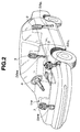
- Fig. 2 is an explanatory view of an arrangement of the shock absorber damping force controlling apparatus in a first preferred embodiment according to the present invention.
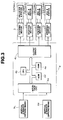
- Fig. 3 is a circuit block diagram of a control unit and its peripheral circuit of the shock absorber damping force controlling apparatus shown in Fig. 2.
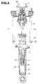
- Fig. 4 is a partially sectional view of each shock absorber SA used in the first embodiment shown in Figs. 2 and 3.
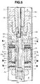
- Fig. 5 is an enlarged, partially sectional view of the representative shock absorber SA shown in Fig. 3.
- Fig. 6 is a characteristic graph representing damping forces with respect to a piston speed of the representative shock absorber shown in Figs. 4 and 5.
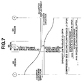
- Fig. 7 is a damping coefficient characteristic graph representing a damping force region corresponding to a stepped position of an adjuster according to the rotation of a representative pulse (stepping) motor shown in Figs. 2 and 3.
- Figs. 8A, 8B, and 8C are cross sectional views cut away along a line K - K of Fig. 7 representing an essential part of the representative shock absorber shown in Figs. 4 and 5.
- Figs. 9A, 9B, and 9C are cross sectional views cut away along lines L - L and M - M of Fig. 7 representing an essential part of the representative shock absorber shown in Figs. 4 and 5.
- Figs. 10A, 10B, and 10C are cross sectional views cut away along a line N - N of Fig. 7 representing an essential part of the representative shock absorber shown in Figs. 4, and 5.
- Fig. 11 is a damping force characteristic graph when an extension stroke side with respect to the piston of the representative shock absorber shown in Fig. 4.
- Fig. 12 is a damping force characteristic graph when both extension and compression stroke sides are in soft damping force states.
- Fig. 13 is a damping force characteristic graph when the compression stroke side is in a hard damping force state.
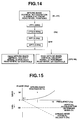
- Fig. 14 is a signal processing circuit for an input sprung mass vertical acceleration signal G in the case of the first embodiment shown in Figs. 2 through 13.
- Fig. 15 is characteristic graphs representing phase relationships between each signal and input signal frequency.
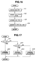
- Fig. 16 is an operational flowchart indicating a control operation to derive control signals executed in a control unit of the first embodiment shown in Figs. 2 through 13.
- Fig. 17 is another operational flowchart of a damping force characteristic control operation in the control unit of the first embodiment shown in Fig. 2.
- Figs. 18A, 18B, 18C, and 18D are waveform timing charts of the damping force characteristic control operation in the control unit of the first embodiment shown in Fig. 2.
- Fig. 19 is a characteristic graph of a transmissivity of the input frequency onto the sprung mass in the case of the first embodiment shown in Figs. 2 through 13.
- Fig. 20 is an explanatory top view of the vehicle in which a vertical acceleration sensor is mounted on a center portion of a vehicular body between the front road wheels in a case of a second embodiment.
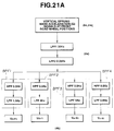
- Fig. 21A is a circuit block diagram of the damping force characteristic controlling apparatus in a third preferred embodiment.
- Fig. 21B is a circuit block diagram of another signal processing circuit in the third embodiment shown in Fig. 21A.
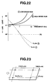
- Fig. 22 is characteristic graphs representing the phase relationships between each signal and input signal frequency in the case of the third embodiment.
- Fig. 23 is an explanatory top view of the vehicle in which three sprung mass vertical acceleration sensors are mounted in a case of a fourth preferred embodiment.
- Fig. 24 is a circuit block diagram of the damping force characteristic controlling apparatus in the fourth embodiment shown in Fig. 23.
- Fig. 25 is a gain characteristic graph with respect to a vehicle speed in the case of the fourth embodiment shown in Figs. 23 and 24.
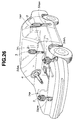
- Fig. 26 is an explanatory view of the damping force characteristic controlling apparatus in a case of a fifth preferred embodiment.
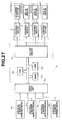
- Fig. 27 is a schematic circuit block diagram of the damping force characteristic controlling apparatus in the case of the fifth embodiment shown in Fig. 26.
- Fig. 28 is a schematic circuit block diagram of another signal processing circuit in the fifth embodiment shown ion Figs. 26 and 27.
- Fig. 29 is an operational flowchart representing a control signal driving routine in the case of the fifth embodiment.
- Fig. 30 is an explanatory side view of the vehicle for explaining a derivation of a sprung mass vertical acceleration at a part of the vehicular body which is remote from the rear road wheel portions by b in the case of the fifth embodiment.
- Fig. 31 is an explanatory top view of the vehicle in which two sprung mass vertical acceleration sensors are arranged in a case of sixth preferred embodiment.
- Fig. 32 is an explanatory top view of the vehicle in which three sprung mass vertical acceleration sensors are arranged in a case of a seventh preferred embodiment.
- Fig. 33 is a schematic circuit block diagram of the damping force characteristic controlling apparatus in the seventh embodiment shown in Fig. 32.
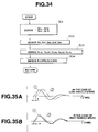
- Fig. 34 is an operational flowchart representing a control signal deriving routine in the case of the seventh embodiment shown in Figs. 32 and 33.
- Figs. 35A and 35B are characteristic graphs presenting phase lag states of the vertical sprung mass velocity signal at the rear road wheel position with respect to the vertical sprung mass velocity signal at the front road wheel position, Fig. 35A indicating those when the vehicle runs at a high speed and Fig. 35B indicating those when the vehicle runs at a low speed.
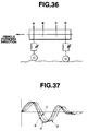
- Fig. 36 is an explanatory view representing the detected position of the sprung mass vertical velocity as viewed from a vehicular body side for explaining the operation in the seventh embodiment.
- Fig. 37 is characteristic graphs representing phase lag states of the respective sprung mass vertical velocity signals at the respective sprung mass vertical velocity detecting positions in the case of the seventh embodiment shown in Fig. 36.
- Fig. 38 is an explanatory view of the damping force characteristic controlling apparatus in an eighth preferred embodiment.
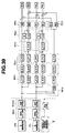
- Fig. 39 is a schematic circuit block diagram of the damping force characteristic controlling apparatus in the eighth embodiment.
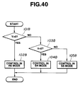
- Fig. 40 is an operational flowchart representing a damping force characteristic controlling routine in the case of the eighth embodiment.
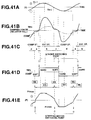
- Figs. 41A through 41E are integrally a timing chart of the damping force characteristic control operation in the case of the eighth embodiment.
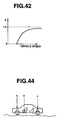
- Fig. 42 is a function map of a value of weighting coefficient K determining a ratio of synthesis in a signal synthesizing circuit in the eighth embodiment.
- Figs. 43A through 43D are signal timing charts representing phase relationships between each signal and actually measured value of the sprung mass vertical velocity at the rear road wheel position.
- Fig. 44 is a schematic side view of the vehicle in which the vertical acceleration sensors are mounted in the case of the eighth embodiment shown in Figs. 39 through 43B.
- Figs. 45A and 45B are signal timing charts representing phase relationships between the respective sprung mass vertical velocity signals detected and output at the sensor mounted parts of the vehicular body shown in Fig. 44, Fig. 45A being the case where the vehicle speed falls in a middle or low speed region and Fig. 45B being the case where the vehicle speed falls in a high speed region.
- Fig. 46 is a three-dimensional characteristic graph representing phase differences between the respective sprung mass vertical velocity signals detected and output from the respective sprung mass vertical velocity determining circuits located at the respective positions of the vehicular body shown in Fig. 44.
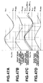
- Figs. 47A through 47D are signal timing charts representing relationships between the front road wheel side control signals and front road wheel side target damping force positions, and relationships between the rear road wheel side control signals and rear road wheel side target damping force positions when the vehicle speed falls in the middle or low speed range.
- Figs. 48A and 48B are signal timing charts representing relationships between the front/ rear road wheel side control signals and the front/rear road wheel side target damping force positions when the vehicle speed falls in the high speed range.
- Figs. 49A through 49D are signal timing charts of the front road wheel side control signals, rear road wheel side control signals, and actually measured values of the sprung mass vertical velocity signal derived at a rear tower position in an actual test of running the vehicle on a impulse road surface, Fig. 49A being those in the state where the vehicle runs at 40 Km/h, Fig. 49B being those in the state where the vehicle runs at 50 Km/h, Fig. 49C being those in the state where the vehicle runs at 70 Km/h, and Fig. 49D being those in the state where the vehicle runs at 100 Km/h.
- Fig. 2 shows a whole system configuration of a vehicular shock absorber damping force characteristic controlling apparatus in a first preferred embodiment according to the present invention.
- shock absorbers SA FL , SA FR , SA RL , and SA RR are interposed between given parts of a vehicular body (sprung mass) and respective road (tire) wheels (unsprung mass).
- the road wheels comprise front left tire wheel, front right tire wheel, rear left tire wheel, and rear right tire wheels of the vehicle. It is noted that the above-described given parts of the vehicular body indicate front left and right road wheel positions and rear left and right road wheel positions.
- a pair of front left and right sprung mass vertical acceleration sensors I FL , I FR are attached onto the given parts of the vehicular body, namely, onto the front left and right road wheel positions adjacent to the corresponding front left and right road wheels, each of the front left and right road wheels being suspended by the corresponding shock absorbers SA FR and SA FL .
- the pair of front left and right sprung mass vertical acceleration sensors 1 (1 FL , 1 FR ) serve to detect sprung mass vertical accelerations at the front left and right road wheel positions of the vehicular body.
- a control unit 4 is installed on a portion of the vehicular body near to a driver's seat.
- the control unit 4 receives the sprung mass vertical acceleration signals G (gravity) (G FL , G FR ) from the respective front left and right road wheel side sprung mass vertical acceleration (G) sensors 1 FL , 1 FR and outputs a drive signal to a corresponding one 3 of stepping (pulse) motors so as to change the damping force characteristic of the corresponding one SA of the shock absorbers as will be described later.
- G gravitation
- Fig. 3 shows a circuit block diagram of the damping force characteristic controlling apparatus in the first preferred embodiment according to the present invention.
- the control unit 4 includes an interface circuit 4a, CPU (Central Processing Unit) 4b, ROM 4d, and RAM 4e, and an output driver 4c.
- CPU Central Processing Unit
- the interface circuit 4a receives the vertical sprung mass acceleration indicative signals (G FL , G FR ) from the pair of the sprung mass vertical acceleration (G) sensors 1 FL and 1 FR at the front left and right road wheel positions shown in Fig. 3.
- Fig. 14 shows a signal processing circuit installed in the interface circuit 4a of the control unit 4.
- the interface circuit 4a includes: a first low pass filter LPF1 which is so constructed as to mainly eliminate noises of a high frequency region (30 Hz or higher) from one of the sprung mass vertical acceleration indicative signals G (G FL , G FR ) of the sprung mass vertical acceleration sensors I FL and I FR ; a second low pass filter LPF2 which is so constructed as to mainly integrate the sprung mass vertical acceleration signal G (G FL , G FR ) passed through the first low pass filter LPF1 so as to derive a sprung mass vertical velocity signal indicating the sprung mass vertical velocity; a first high pass filter HPF having a cut-off frequency of 0. 3 Hz; and a third low pass filter LPF3 having a cut-off frequency of 3.
- both first and third high-pass and low-pass filters HPF and LPF3 constituting a band-pass filter BPF to derive the sprung mass vertical velocity signal V n including a sprung mass resonance frequency signal component. It is noted that these filters are connected in series with one another as shown in Fig. 14 and the same structure of the signal processing circuit shown in Fig. 14 is provided in the other sprung mass vertical acceleration signal of the other vertical sprung mass acceleration (G) sensor (1 FL , 1 FR ) shown in Fig. 3.
- Fig. 4 show a cross sectional view of each shock absorber SA (SA FL through SA FR ).
- the shock absorber SA includes: a cylinder 30, a (movable) piston 31 defining an upper portion chamber A and a lower portion chamber B; an outer envelope 33 in which a reservoir chamber 32 is formed on an outer peripheral end of the cylinder 30; a base 34 which defines the lower chamber B and the reservoir chamber 32; a guide member 35 which guides a sliding motion of a piston rod 7 with the other end of which the movable piston 31 is linked; a suspension spring 36 interposed between the outer envelope 33 and vehicle body; and a bumper rubber 37.
- Each stepping motor 3 shown in Figs. 2 and 3 is installed in an upper position of the corresponding one of the shock absorbers SA, as shown in Fig. 4, so as to operatively rotate an adjuster 40 (refer to Fig. 5) via a control rod 70 in response to a rotation drive signal from the output driver 4c.
- a rotating shaft of the corresponding one of the stepping motors 3 is mechanically connected to the corresponding adjuster 40 within each shock absorbers SA via the control rod 70.
- Fig. 5 shows an enlarged cross sectional view representing a part of the piston assembly 31 and its surrounding part of each of the shock absorbers SA.
- the piston 31 is formed with penetrating holes 31a and 31b.
- the piston 31 is provided with a compression stroke side attenuation valve 20 and an extension stroke side attenuating valve 12 respectively opening and closing the respective penetrating holes 31a and 31b.
- a stud 38 is spirally meshed with and fixed to a bound stopper 41 spirally meshed with and fixed to a tip end of the piston rod 7.
- the stud 38 is penetrated through the piston 31.
- the stud 38 is formed with a communication hole 39 which communicates the upper portion chamber A and the lower portion chamber B.
- the adjuster 40 which changes a flow passage cross sectional area of the communication hole 39 is provided in the piston assembly.
- an extension stroke side check valve 17 and a compression stroke side check valve 22 are also installed which enable and disable the fluid flow through the communication hole 39 in accordance with the direction of the flow of the fluid.
- the stud 38 is formed with a first port 21, a second port 13, a third port 18, a fourth port 14, and fifth port 16, respectively in an upper order.
- the adjuster 40 is formed with a hollow portion 19, a first lateral hole 24, and a second lateral hole 25, both lateral holes communicating the internal and external portions of the adjuster 40.
- a longitudinal groove 23 is formed on an outer peripheral portion.
- four flow passages are formed between the upper portion chamber A and lower portion chamber B as the fluid flow passages when the piston stroke indicates the extension stroke: that is to say, 1) an extension stroke side first flow passage D such that the fluid passes the penetrating hole 31b, a valve opened internal side of the extension stroke side attenuation valve 12, and reaches the lower portion chamber B; 2) an extension stroke side second flow passage E in which the fluid flows through the second port 13, the longitudinal groove 23, the fourth port 14, a valve opened outer peripheral side of the extension stroke side attenuating valve 12, and reaches the lower portion chamber B; 3) an extension stroke side third flow passage F in which the fluid passes through the second port 13, the longitudinal groove 23, and the fifth port 16; and 4) a bypass flow passage G in which the fluid passes through the third port 18, the second lateral hole 25, and the hollow portion 19 and reaches the lower portion chamber B.
- the three fluid flow passages through which the fluid can be caused to flow during the compression stroke side of the piston 31 include: 1) a compression stroke side first flow passage H in which the fluid flows through the penetrating hole 31a and valve opened compression stroke side attenuating valve 20; 2) a compression stroke side second flow passage J in which the hollow portion 19, the first lateral hole 24, the first port 21, and the opened compression stroke side check valve 22 and reaches the upper portion chamber A; and 3) the bypass passage G in which the fluid flows through the hollow portion 19, the second lateral hole 25, and the third port 18.
- the shock absorber SA is so constructed as to be enabled to change the damping force characteristics at a multiple stage in its damping characteristic, as shown in Fig. 6, either in the extension stroke side or compression stroke side when the adjuster 40 is pivoted according to the rotation of the corresponding one of the stepping motors 3.
- Fig. 7 sows relationships between the rotated position of the adjuster 40 and damping force characteristics at both the extension stroke and compression stroke sides with respect to the piston 31.
- the damping force coefficient at the extension stroke side can be changed at the multiple stage from a maximum hard to a minimum hard characteristic but the compression stroke side is fixed at a soft position (hereinafter, referred to as an extension stroke side hard region HS).
- the damping force coefficient at the compression stroke side is only changeable to a hard region from the maximum hard to the minimum hard characteristic at the multiple stages and the damping force characteristic at in the compression stroke side is fixed to the soft position (hereinafter, referred to as a compression hard region SH).
- FIG. 7 When, as shown in Fig. 7, the adjuster 40 is pivoted at any one of positions 1, 2, and 3, cross sections of the piston assembly portions cut away along lines K -K, L - L, M - M, and N - N of Fig. 5 are respectively shown in Figs. 8A (1), 8B (2), and 8C (3) (K-K), 9A (1), 9B (2), and 9C (3) (L - L, M - M), 10A ( 1), 10B (2), and 10C (3) (N - N), respectively.
- the damping force characteristics at the respective positions 1 , 2, and 3 shown in Fig. 7 are shown in Figs. 11, 12, and 13, respectively.
- Fig. 6 shows an operational flowchart for deriving control signals (this control signal is representatively denoted by V) for the respective front and rear road wheel side shock absorbers SA (SA FL through SA RR ) by means of the control unit 4.
- the CPU 4b fetches data on the sprung mass vertical acceleration acted upon the given parts of the vehicular body G FL , G FR on which the front left and right side shock absorbers SA FL , SA FR are mounted from the pair of front left and right sprung mass vertical G sensors I FL and I FR .
- the CPU 4b fetches data on the sprung mass vertical velocity V n (V n-FL ---- front left road wheel side, V n-FR --- front right road wheel side) derived from the signal processing circuit shown in Fig. 14 by integrating each of the sprung mass vertical acceleration indicative signals G FL and G FR and derives a bouncing component FCV B acted upon a center position of the vehicular body (sprung mass) located at a center between the front left and right road wheel sides using the following formula (1).
- the sprung mass vertical velocity V n has a positive value when a direction of the velocity V n is upward (height direction of the vehicle body) and has a negative value when a direction thereof is downward (ground direction of the vehicle body).
- FCV B V n - FL + V n - FR )/2 (1)
- the CPU 4b derives each rolling component V R (FLV R , FRV R ) acted upon the vehicular body at the corresponding one of the given parts on which the front left and right shock absorbers SA FL and SA FR are suspended.
- FLV R V n -FL - V n - FR
- FRV R V n - FL - V n - FL (2)
- FL denotes the front left road wheel side
- FR denotes the front right road wheel side.
- the CPU 4b derives each control signal V for the corresponding one of the respective shock absorbers SA on the basis of the corresponding one of the following equations (3).
- FLV ⁇ f ⁇ FCV B + ⁇ f ⁇ FLV R
- FRV ⁇ f ⁇ FCV B + ⁇ f ⁇ FRV R
- RLV ⁇ r ⁇ FCV B + ⁇ f ⁇ FLV R
- RRV ⁇ r ⁇ FCV B + ⁇ f ⁇ FRV R (3) ⁇ f , ⁇ f ; each proportional constant for FLV B and for FRV R , ⁇ f , ⁇ f ; each proportional constant for FLV R and for FRV R .
- Each first term of a right side in the corresponding one of the equations (3) denotes a bouncing rate and each second arm of the right side in the corresponding one of the equations (3) denotes a rolling rate.
- the routine to derive the control signals is ended at the step 104 and the routine returns to the step 101 to repeat the above driving steps.
- control signals RLV and RRV for the rear left and right road wheel sides are derived on the basis of the vehicular body bouncing component FCV B at the positions of the front left and right shock absorbers SA FL and SA FR and rolling components FL VR and FRV R at the front right and left shock absorbers SA FL and SA FR in the same way as those control signal FLV and FRV at the front road wheel side so that the control signals V which are corrected in terms of the phase deviations due to the signal processing.
- Fig. 15 which shows the phase characteristics of each signal with respect to the input frequency
- the phase state of the signal processed sprung mass vertical velocity V n is, as denoted by a broken line, advanced with respect to the phase of the input sprung mass vertical acceleration signal G when the input frequency becomes low and is delayed with respect to that G when the input frequency becomes high ( in the direction such as to be delayed in proportion to a magnitude (value) of the frequency).
- a phase of the sprung mass vertical acceleration signal detected at the front road wheel side with respect to a sprung mass vertical acceleration signal to be detected at the rear road wheel side is advanced in proportion to the magnitude of the input frequency.
- the phase delay due to the signal processing as described above can be eliminated at the rear road wheel side.
- the vehicular comfort can be improved since the phase delay problem at the higher frequency side than the sprung mass resonance frequency can be eliminated.
- Fig. 19 shows characteristic graphs of transmissitivities of input frequency onto the sprung mass (vehicular body) when the first embodiment is carried out and when the previously proposed damping force characteristic control apparatus is carried out.
- a transmissivity (or transmittance or transmissibility) of the input frequency to the sprung mass at higher frequency range than the resonance frequency point (1E + 00) is reduced than that of the previously proposed damping force characteristic controlling apparatus described in the BACKGROUND OF THE INVENTION. Consequently, the vehicular body gives the vehicular occupant no feeling of ruggy vibrations and/or of running on the highly consecutive running of rough roads.
- Fig. 17 shows an operational flowchart of controlling the damping force characteristic of each shock absorber SA on the basis of the control signal V.
- the CPU 4b determines whether the control signal V is higher than a predetermined positive threshold value ⁇ T . If Yes at the step 201, the CPU 4b controls the corresponding one of the shock absorbers SA at a step 202 in such a mode that the extension stroke side provides the hard region and the compression stroke side provides the soft region (so called, extension stroke side hard region HS). If No at the step 201, the routine goes to a step 203 in which the CPU 4b determines whether the control signal V, in turn, is less than a predetermined negative threshold value ⁇ C .
- the routine goes to a step 204 in which the CPU 4b issues the command to the driver 4c to control the corresponding one of the shock absorbers SA in the control of SH mode in which the compression stroke side is at the hard damping force characteristic side and the extension stroke side is at the soft region (SH). If No at the step 203 ( + ⁇ T ⁇ V ⁇ - ⁇ C ), the routine goes to a step 205 in which CPU 4b issues the command to the driver 4c to control the damping force characteristic of the corresponding one of the shock absorbers SA in the SS region mode in which both extension stroke and compression stroke sides are in the soft regions (SS).
- Figs. 18A through 18E show timing charts of the control operations in the damping force characteristic controlling apparatus in the first embodiment.
- the control signal V based on the sprung mass vertical velocity signal V n has a value which falls between the predetermined positive and negative threshold values ⁇ T and - ⁇ C , the representative shock absorber SA is controlled in the SS mode (both extension and compression stroke sides are in the soft regions).
- the extension stroke side region is controlled in the HS region (hard damping force characteristic side in which the damping force characteristic is varied in proportion to the value of the control signal V.
- the compression stroke side is controlled in the compression stroke side hard region SH and the damping force characteristic at the compression stroke side is varied in accordance with the value of the control signal V with the compression stroke side fixed to the soft region.
- the same control as a damping force characteristic based on a sky hook theory can be carried out only using the pair of the front road wheel side sprung mass vertical acceleration sensor 1. Furthermore, when the control regions are transferred from the region a to the region b and from the region c to the region d, the switching of the damping force characteristic can be carried out without the drive to the corresponding one of the stepping motors 3.
- Fig. 20 shows a second preferred embodiment of the damping force characteristic controlling apparatus according to the present invention.
- the other structure of the damping force characteristic controlling apparatus is generally the same as that in the first embodiment.
- a single sprung mass vertical acceleration sensor 1 FC is installed on the vehicular body at the generally center position between the given parts of the vehicular body on which the front left and right road wheel side shock absorbers SA FL and SA FR are suspended.
- the control signal V derived on the basis of the sprung mass vertical velocity signal V n - FC located at the center position of the front road wheel sides is used to control the damping force characteristics of all of the shock absorbers SA FL , SA FR , SA RL , and SA RR at the simultaneous time.
- the same advantages as described in the first embodiment can be achieved except the rolling control (the rolling rate cannot be achieved in the second embodiment) as in the case of the first embodiment.
- the apparatus system cost can accordingly be reduced.
- Fig. 21A shows the circuit block diagram of the damping force characteristic controlling apparatus in a third embodiment according to the present invention
- Fig. 21B shows the signal processing circuit of the interface circuit and derivation of the front left and right and rear left and right control signals from the signal processing circuit passed signals in a third preferred embodiment according to the present invention.
- the third embodiment four series-connected band pass filters BPF1, BPF2, BPF3, and BPF4 are installed.
- the first low-pass filter LPF1 has the cutoff frequency of 30Hz.
- the second low-pass filter LPF2 has the cut-off frequency of 0. 05 Hz.
- a first band pass filter BPF1 shown in Fig. 21A is a band pass filter to derive the front road wheel side sprung mass vertical velocity V n (V n - Fh ) for the controls of the front road wheel side shock absorbers SA FL and SA FR when the vehicle speed falls in a high speed range and is constituted by a high pass filter HPF having the cut-off frequency of 0. 5 Hz and a low pass filter having the cut-off frequency of 1. 5 Hz.
- a second band pass filter BPF2 shown in Fig. 21A is a band pass filter to derive the front road wheel side sprung mass vertical velocity V n (V n - Fl ) for the controls of the front road wheel side shock absorbers SA FL and SA FR when the vehicle speed falls in a low speed range and is constituted by a high pass filter LPF having the cut-off frequency of 0. 5 Hz and a low pass filter LPF having the cut-off frequency of 4 Hz.
- a third band pass filter BPF3 shown in Fig. 21A is a band pass filter to derive the rear road wheel side sprung mass vertical velocity V n (V n - Rh ) for the controls of the rear road wheel side shock absorbers SA RL and SA RR when the vehicle speed falls in the high speed range and is constituted by a high pass filter HPF having the cut-off frequency of 0. 8 Hz and a low pass filter having the cut-off frequency of 5 Hz (refer to the phase characteristic denoted by a dotted line of 2 of Fig. 22).
- a fourth band pass filter BPF4 shown in Fig. 21 is a band pass filter to derive the rear road wheel side sprung mass vertical velocity V n (V n - Rl ) for the controls of the rear road wheel side shock absorbers SA RL and SA RR when the vehicle speed falls in the low speed range and is constituted by a high pass filter having the cut-off frequency of 0. 8 Hz and a low-pass filter having the cut-off frequency of 0. 8 Hz (refer to the phase characteristic denoted by a dotted line of 1 of Fig. 22).
- Fig. 22 shows phase characteristics of the respective signals with respect to the input signal frequency.
- the solid lines 1 and 2 shown in Fig. 22 denote phase characteristics of the respective signals with respect to the input signal frequency when the vehicle runs at the high speed and when the vehicle runs at the low speed, the solid line 1 indicating the phase advance of the sprung mass vertical acceleration signal detected at the front road wheel side with respect to the phase of the sprung mass vertical acceleration signal to be detected at the rear road wheel side and the phase advance quantity being the function of the vehicle speed and the solid line 2 indicating the phase advance of the sprung mass vertical acceleration signal detected at the front road wheel side with respect to the sprung mass vertical acceleration signal detected at the rear road wheel side to be detected at the rear road wheel side and the phase advance quantity being the function of the vehicle speed.
- the signal processed band pass filter BPF1 having the narrower cut-off frequency band for the high speed range is switched to the signal processed band pass filter BPF2 having the higher cut-off frequencies for the low speed range when the vehicle speed falls in the low speed range to appropriately derive the control signals for the front road wheel side shock absorbers SA FL and SA FR .
- the high speed band pass filter BPF3 by which the phase characteristic of the processed signal denoted by the dotted line of 2 is carried out at a predetermined vehicle speed value, the variation of the phase advanced state of the front road wheel sprung mass vertical acceleration signal detected at the front road wheel side with respect to the phase to be detected at the rear road wheel side due to the vehicle speed can be corrected.
- the damping force characteristic controlling apparatus in the third embodiment can be achieved using only one sprung mass vertical acceleration sensor I FC located at the center position of the front road wheel side shock absorbers as in the case of the second embodiment.
- Fig. 23 shows an arrangement of three sprung mass vertical acceleration sensors mounted on the vehicular body in a case of a fourth preferred embodiment.
- Fig. 24 shows a schematic circuit block diagram of a vehicular damping force characteristic controlling apparatus in the forth embodiment.
- another sprung mass vertical acceleration sensor 1 RR is installed on the given part of the vehicular body on which the rear right road wheel side shock absorber SA RR is suspended in addition to the sprung mass vertical acceleration sensors I FR and I FL described in the case of the first embodiment.
- the vehicle speed sensor 2 which is constructed as to detect the vehicle speed is connected to a control signal calculating block 430.
- the damping force characteristic controls for the front road wheel side shock absorbers SA FL and SA FR are carried out on the basis of the control signals FLV and FRV formed by means of the sprung mass vertical velocity signals V n - FL and V n - FR at the front road wheel sides derived from the front road wheel side vertical sprung mass G sensors I FL and I FR .
- the damping force characteristic controls for the rear left and right road wheel side shock absorbers SA RL and SA RR are carried out on the basis of the control signals RLV and RRV formed by the rear right road wheel side sprung mass vertical velocity V n - RR derived from the rear road wheel side sprung mass vertical acceleration sensor I RR and a calculated rear left road wheel side sprung mass vertical velocity V n - RL at the rear road wheel side, respectively, when the vehicle speed detected by the vehicle speed sensor 2 indicates a low speed (lower than 30 Km/h).
- each of the front road wheel side sprung mass vertical velocity signals V n - RL and V n - RR is synthesized with the corresponding one of the front road wheel side sprung mass vertical velocity signals V n - FL and V n - FR , a rate of synthesis of both signals being such that as the vehicle speed increases the rate of synthesis of the front road wheel side sprung mass vertical velocity signal V n - FL and V n - FR to the other rear road wheel side sprung mass velocity signal V n - RL and V n - RR , as shown in a gain characteristic graph of Fig. 25, the rear road wheel side sprung mass vertical velocity V n - RL and V n - RR being accordingly reduced.
- the control unit 4 in the fourth embodiment, comprises a position correction calculating block 410, a signal processing block 420 used to derive the signals having the frequency dependent characteristics including the speed conversion, and the control signal calculating block 430, as shown in Fig. 24.
- both of the front road wheel side and rear road wheel side shock absorbers SA FL through SA RR are independently controlled so as to maintain the vehicular pitching motion suppression.
- the damping force characteristic controls for the front road wheel side shock absorbers are carried out on the basis of the control signals based mainly on the sprung mass vertical velocity signals V n - FL and V n - FR derived at the front road wheel side so that the same advantages as in the case of the first embodiment can be achieved.
- the rate of signal synthesis is the function of the vehicle speed, a more precise control for the rear road wheel side shock absorbers SA RL and SA RR can be carried out.
- the sprung mass vertical G sensors includes the pair of front left and right sprung mass vertical G sensors I FL and I FR and the rear right road wheel side vertical G sensor I RR located at the rear right road wheel side
- the sprung mass vertical G sensors may include a single front center sprung mass vertical acceleration sensor located at the center between the front left and right road wheel sides and a single rear center sprung mass vertical acceleration sensor located at the center between the rear left and right road wheel sides.
- the sprung mass vertical G sensor(s) are used as the vertical behavior detecting means, either such a sensor(s) as to detect a relative displacement between the sprung mass and unsprung mass or a combination thereof or either such as a sensor(s) as to detect the relative velocity between the sprung mass and unsprung mass or the combination thereof may be used.
- shock absorbers SA FL through SA RR are used in which one of the stroke sides is controlled to provide the hard damping force while the other stroke side is fixed to the soft damping force characteristic, such shock absorbers that both extension and compression stroke sides are controlled simultaneously and in the same directions may alternatively be used.
- band pass filters BPF1 and BPF2 or BPF3 and BPF4 are switched in accordance with the vehicle speed
- three or more types of the band pass filters may be disposed to enhance the control effects.
- the rate of signal synthesis of the front road wheel side sprung mass vertical velocities V n - FL and V n - FR to the sprung mass vertical velocity signals V n - RL and V n - RR derived at the rear road wheel side is the function of the vehicle speed
- the rear left and right road wheel side shock absorbers SA RL and SA RR may be controlled on the basis of the control signals based on the front road wheel side sprung mass vertical velocity signals V n - FL and V n - FR .
- Figs. 26 shows the damping force characteristic controlling apparatus in a fifth preferred embodiment
- Fig. 27 shows the schematic circuit block diagram of the damping force characteristic controlling apparatus in the fifth embodiment.
- the rear left and right road wheel acceleration sensors I RL and I RR are newly added to detect the sprung mass vertical accelerations located at the rear left and right road wheel sides as compared with the first embodiment.
- the other structures of the apparatus is generally the same as those in the first embodiment.
- Fig. 28 shows the representative signal processing circuit in the interface circuit shown in Fig. 27.
- the arrangement of the signal processing circuit is generally the same as that shown in Fig. 14 .
- the second low pass filter LPF1 has the cut-off frequency of 0.1 Hz
- the high pass filter HPF has the cut-off frequency of 1.0 Hz
- the third low pass filter LPF3 has the cut-off frequency of 1.5 Hz.
- Fig. 29 shows the operational flowchart executed by the CPU 4b in the fifth embodiment to derive the control signal V (FLV, FRV, RLV, and RRV).
- the CPU 4b fetches data on the sprung mass vertical accelerations at the respective road wheel sides (G FL , G FR , G RL , and G RR ) from the respective sprung mass vertical acceleration sensors (I FL , I FR , I RL , and I RR ).
- the CPU 4b calculates the sprung mass vertical acceleration G' r (G' rL , G' rR ) at a position of the vehicular body which is forward by a predetermined length b denoted in Fig. 30 with respect to the rear road wheel position from the front road wheel side sprung mass vertical acceleration G F (G FL and G FR ) and the rear road wheel side sprung mass vertical acceleration G R (G RL , G RR ) on the basis of the following equation (5).
- G' r G R + b/a (G F - G R ) (5), wherein symbol a denotes a wheel base length.
- the CPU 4b integrates the four sprung mass vertical acceleration signals G FL , G FR , G' rL , and G' rR to convert them into the sprung mass vertical velocity signals and render the sprung mass vertical velocity signals pass through the band pass filter BPF of the high pass filter and third low pass filter shown in Fig. 28 to derive the sprung mass vertical velocity signals V n (V n - FL , V n - FR , V' nL , V' nR ) including the sprung mass resonance frequency components.
- the CPU 4b derives the control signal V for each shock absorber SA using the following equations (6).
- FLV ⁇ f ⁇ V n - FL
- FRV ⁇ f ⁇ V n - FR
- RLV ⁇ r ⁇ V' nrL
- RRV ⁇ r ⁇ V' nrR (6)
- the routine is ended and returns to the step 101A of Fig. 29.
- the control signals for the rear road wheel side shock absorbers RLV and RRV are derived according to the input sprung mass velocity signals V' nrL and V' nR of the position located in front of a line (generally called a tread) connecting both rear left and right road wheels) so that the control signals V which have corrected the phase deviations due to the signal processing can be derived.
- the damping force control routine as the first embodiment shown in Fig. 17 is carried out in the case of the fifth embodiment.
- Fig. 31 shows a sixth preferred embodiment of the damping force characteristic controlling apparatus according to the present invention.
- a pair of sprung mass vertical acceleration sensors I FC and I RC are installed on the respective center positions (FC and RC of Fig. 31) of the vehicular body with respect to the respective lines connecting both front left and right road wheels and rear left and right road wheels.
- control signal V is calculated on the basis of the sprung mass vertical velocity signal V n - FC at the center position of the vehicular body between the front road wheels derived from the front side sprung mass vertical acceleration signal I FC and is used to control the damping force characteristics of the front left and right road wheel side shock absorbers SA FL and SA FR .
- control unit 4b calculates the sprung mass vertical velocity signal V' n -RC located at the center position which is forward by the predetermined length b with respect to the line connecting both rear left and right road wheels from the sprung mass vertical velocity signal V n - RC at the center position of the vehicular body between the rear left and right road wheels and carries out the damping force characteristic controls of the rear road wheel side shock absorbers SA RL and SA RR .
- the number of sensors of the sprung mass vertical acceleration sensors are two so that the cost of assembling the apparatus in the vehicle can be reduced.
- Fig. 32 shows the arrangement of sensors in a case of a seventh preferred embodiment of the damping force characteristic controlling apparatus.
- Fig. 33 shows a schematic circuit block diagram of the damping force characteristic controlling apparatus in the seventh embodiment.
- the pair of the left and right sprung mass vertical acceleration sensors I FL and I FR are mounted on the given parts of the vehicular body which are remote in the rearward direction by a distance x from the corresponding one of the front left and front right road wheel sides denoted by dotted circles of Fig. 32 and the sprung mass vertical acceleration sensor I RR to detect the sprung mass acceleration at the position of the vehicular body which is located at the rear right road wheel side is installed.
- the CPU 4b in the seventh embodiment calculates four values of four point detection target positions on the vehicular body, i.e., sprung mass vertical acceleration signals G' fL and G' fR at the front left and right road wheel sides denoted by the dotted circles of Fig. 32 and sprung mass vertical acceleration signals G' rL and G' rR of the parts of the vehicular body which are in front of the rear left and right road wheel sides by a given distance denoted by y of Fig. 32.
- the distance y is moved in the forward direction in proportion to the vehicle speed.
- the control unit 4 includes an x-y position calculating block 410A; a position correction calculating block 420A; a target position acceleration calculating block 430A; a each component calculating block 440A; a velocity conversion block 450A; a band pass filter 460A; a control signal calculating block 470A; and a damping force characteristic control block 480A.
- Fig. 34 shows a control routine representing the derivation of the control signals V.
- the CPU 4b calculates the front road wheel side sprung mass vertical acceleration signals G' rL and G' rL from the three point sprung mass vertical acceleration signals G FL , G FR , and G RR on the vehicular body from the three point located sprung mass vertical G sensors I FL , I FR and I RR and calculates the rear road wheel side sprung mass vertical accelerations G' rL and G' rR at the front position by the distance y from the rear road wheel position.
- the CPU 4b derives G' fL , G' fR , G' rL , and G' rR using the following equations (7):
- L o denotes a wallabies length
- L1 denotes the tread (the tread means the distance between the center points of contact with the ground of the two front wheels or the two rear wheels of the vehicle)
- L2 denotes a distance in the vehicular width direction from the position on which the rear right road wheel side sprung mass vertical G sensor I RR is mounted.
- x and y are the first-order function to the vehicle speed. As the vehicle speed increases, the target positions are moved forward.
- x ⁇ f ⁇ speed + x o
- y ⁇ r ⁇ speed + y o
- ⁇ f and ⁇ r denotes initial values of x and y, respectively.
- the CPU 4b derives the vehicular bouncing component G B , pitching components G pf , G pr , and rolling components G Rf and G Rr on the basis of the following equations (9) from the calculated sprung mass vertical accelerations G' fL and G' fR and calculated sprung mass vertical accelerations G' rL and G' rR at the respective target positions.
- the CPU 4b integrates the respective sprung mass vertical acceleration signal components of G B , G pf , G pr , G Rf , and G Rf caused by the sprung mass vertical accelerations to be converted into the bouncing component V n - B , pitching components V n - Pf and V n - Pr , and rolling components V n - Rf and V n - Rr , respectively.
- the band pass filter BPF is constituted by the high pass filter having the cut-off frequency of 0.5 Hz and the third low pass filter having the cut-off frequency of 2.5 Hz to filter the respective bouncing, pitching, and rolling components so as to eliminate unnecessary signal components.
- the control signals V for the respective shock absorbers SA are calculated on the basis of the following equations (9).
- FLV ⁇ f ⁇ V n - B + ⁇ f ⁇ V n - Rf + ⁇ f ⁇ V n - Rf
- FRV ⁇ f ⁇ V n - B + ⁇ f ⁇ V n -Pf - ⁇ f ⁇ V n - Rf
- RLV ⁇ r ⁇ V n - B + ⁇ r ⁇ V n -Pr + ⁇ r ⁇ V n - Rr
- RRV ⁇ r ⁇ V n - B + ⁇ r ⁇ V n - Pr - ⁇ r ⁇ V n - Rr .
- ⁇ f , ⁇ f , and ⁇ f denote proportional constants of the front road wheel sides and ⁇ r , ⁇ r , and ⁇ r denote proportional constants of the rear road wheel sides.
- step 304 returns to the step 301, in the same way as in the case of the first embodiment.
- Figs. 25A and 25B show the sprung mass vertical velocity signal timing charts in the case of the seventh embodiment according to the vehicle speed.
- Fig. 36 shows the sprung mass vertical velocity signal detected positions A, B, C, and D on the given parts of the vehicular body and Fig. 37 shows phase delay states of the sprung mass vertical velocity signals a, b, c, and d at the detected positions of A, B, C, and D viewed from the vehicular body left side.
- the phase advance quantity of the signal at the predetermined forward position with respect to the rear road wheel side becomes large (A denotes the front road wheel position) becomes large. Therefore, the predetermined forward position to the rear road wheel position is moved in the forward direction in proportion to the vehicle speed so that the correction to eliminate the variation of the phase delay due to the variation in the vehicle speed can be made. Consequently, even if the vehicle speed is varied, the vehicular comfort can be improved.
- the seventh embodiment recites that the three sprung mass vertical acceleration sensors are mounted as denoted by I FL , I FR , and I RR shown in Fig. 32, the two sprung mass vertical acceleration sensors may be mounted as in the case of the sixth embodiment shown in Fig. 31.
- the sprung mass vertical acceleration sensor(s) which is arranged for directly detecting the sprung mass vertical acceleration at the forward target point of the vehicular body by the distance y from the rear road wheel position may be used.
- Figs. 38 and 39 show an eighth preferred embodiment of the damping force characteristic controlling apparatus according to the present invention.
- the arrangement of the damping force characteristic controlling apparatus shown in Fig. 38 is the same as that in the first embodiment shown in Fig. 2 but in the eighth embodiment the vehicle speed sensor 2 is provided for detecting the vehicle speed and the vehicle speed indicative signal is supplied to the control unit via an A/D converter.
- Fig. 40 shows the operational flowchart for controlling the damping force characteristics of the respective shock absorbers SA (SA FR through SA RR ).
- control routine shown in Fig. 40 is generally the same as shown in Fig. 17 but the values of the predetermined thresholds are zeroes at steps of 101B and 103B in the case of Fig. 40.
- the CPU 4b issues the command to the driver to control the respective shock absorbers SA in the soft regions SS (both extension and compression strokes are soft damping force characteristics) since the control signal(s) indicates zero.
- Figs. 41A through 41E show timing charts of the respective signals and drives in the corresponding one of the stepping motors 3.
- the shock absorber SA is controlled in the extension stroke side hard region and the compression stroke side is controlled in the soft region (so called, HS region mode). At this time, the damping force characteristic at the extension stroke side is varied in proportion to the control signal V.
- a target damping force characteristic exhibiting position P is calculated on the basis of the following equation.
- P (V/V H-T ) x P Tmax (10)
- V H-T denotes a proportional range at the extension stroke side and its value is updated to the value of the control signal V when the value of the control signal V exceeds the value of the proportional range V H - T so that the target damping force characteristic exhibiting position P is started to be reduced at a time point where the control signal V is folded from its peak value
- P Tmax denotes a maximum (hardest) damping force characteristic exhibiting position at the extension stroke side.
- the shock absorber SA is controlled in the compression hard region SH (extension stroke side is soft and the compression stroke side is hard) mode.
- a target damping force position P is derived on the basis of the following equation (11).
- P (V/V H-C )x P Cmax (11)
- V H - T denotes the proportional range at the compression stroke side and its value is updated to the value of the control signal V when the value of the control signal V exceeds negatively the value of the proportional range V H - T and P Cmax denotes a maximum damping force exhibiting position at the compression stroke side.
- V FL , V FR , V RL , and V RR the generations of the control signals V (V FL , V FR , V RL , and V RR ) will be described below.
- the control unit 4 includes the noise elimination block 4aa; A/D conversion block 4aaa; a rolling component calculating block 4ca; a velocity conversion block 4da which is so constructed as to convert the digital sprung mass vertical acceleration signal to the corresponding sprung mass vertical velocity signal; a control signal range setting block 4e which is so constructed as to eliminate unnecessary frequency regions; a preview signal forming block 4fa; a phase synthesis block 4ga; and a bouncing gain setting block 4h; and a rolling gain setting block 4ja.
- both of the sprung mass vertical acceleration signals G FL and G FR input from the pair of the sprung mass vertical acceleration sensors I FL and I FR are passed through the noise elimination block 4aa and the A/D conversion block 4aaa and are calculated to derive the vehicular rolling component signal V R , the rolling component signal V R being processed by means of the speed conversion block 4da and control range setting block 4ea.
- the rolling gain setting block 4ja multiplies either of front road wheel side rolling gain R f or rear road wheel side rolling gain R j by the passed signal from the control range setting block 4ea to derive a front road wheel side rolling rate (V R ⁇ R f ) or rear road wheel side rolling rate (V R ⁇ R r ).
- the respective sprung mass vertical acceleration signals G FL and G FR input from the respective sprung mass acceleration sensors I FR and I FL are processed through the noise elimination block 4aa, the A/D conversion block 4aaa, the velocity speed conversion block 4da, and the control range setting block 4ea to derive the front left and right road wheel side bouncing component signal FLV B , FRV B .
- the front left and right road wheel side bouncing component signals FLV B and FRV B are supplied to the bouncing gain setting block 4ha which are so constructed as to multiply them by the front road side bouncing gain B f to derive front left road wheel side bouncing rate (FLV B ⁇ B f ) and front right road wheel side bouncing rate (FRV B ⁇ B f ).
- the symbol K denotes a weight coefficient and is shown in Fig. 42.
- the coefficient K is the function of the vehicle speed and indicates zero until the vehicle speed is increased and exceeds a predetermined vehicle speed (except zero speed).
- the front road wheel side bouncing components FLV B and FRV B are increased in proportion to the vehicle speed and when the weighting coefficient K indicates generally one (the vehicle speed gives the maximum), the front road wheel side bouncing components FLV B and FRV B provide directly the signal synthesized bouncing component signals RLV B - L and RRV B - L , respectively. It is noted that if the vehicle speed is reduced and does not indicate the value exceeding the predetermined value shown in Fig. 42, the values of the preview signals FLV -L and FRV -L provide directly the left and right signal synthesized bouncing component signals RLV B-L and RRV B-L .
- rear left and right road wheel side bouncing rates (RLV B -L ⁇ B r ) and (RRV B - L ⁇ B r ) are derived by multiplying the left and right signal synthesized bouncing components FLV B -L and RRV B - L by rear road wheel side bouncing gain B r at the bouncing gain setting block 4ha.
- 43A through 43D show signal timing charts representing phase relationships between the actually measured value of the sprung mass vertical velocity at the position of the rear road wheel side, the front road wheel side bouncing component signal FLV B (FRV B ), the preview signal FLV -L (FRV -L ), and signal synthesized component signal RLV B - L (RRV B - L ).
- the phase of the front road wheel side bouncing component signal FLV B (FRV B ) is advanced to that of the actually measured value of the sprung mass vertical velocity at the rear road wheel sides. Therefore, the preview signal forming block 4fa forms the preview signal FLV -L (FRV -L ) whose phase is further retarded to the actually measured value of the sprung mass vertical velocity at the rear road wheel position and the phase synthesizing block 4ga synthesizes the predetermined ratio ((1 -K): K) of the phase delayed preview signal FLV -L (FRV -L ) with the phase advanced front road wheel side bouncing component signal FLV B (FRV B ), thus deriving the signal phase synthesized bouncing component signal RLV B - L (RRV B - L ) which is in phase with the actually measured value of the sprung mass vertical velocity at the rear road wheel sides.
- the preview signal forming block 4fa forms the preview signal FLV -L (FRV -L ) whose phase is
- Fig. 44 shows a schematic right side view of the vehicle and shows a front tower position a, front occupant seat position b, and a rear tower position.
- the front tower position a is generally defined as a position of the vehicular body above the front tire tread
- the front occupant seat position b is generally defined as the position of the vehicular body above the front occupant seat
- the rear tower position c is generally defined as the position of the vehicular body above the rear tread.
- Figs. 45A and 45B show the phase relationships between the sprung mass vertical velocity signal (a) detected at the front tower position a of Fig. 44, the sprung mass vertical velocity signal (b) detected at the front occupant seat position b of Fig. 44, and the sprung mass vertical velocity signal (c) detected at the rear tower position c of Fig. 44.
- Fig. 46 shows characteristic graphs of the phase relationships at the positions of the vehicular body on which the sprung mass vertical acceleration sensors are to be mounted with the road surface input frequency constant.
- the phase of the sprung mass vertical velocity signal becomes proportionally retarded (delayed) when the detected position is moved from the front tower position to the rear tower position and the phase difference between the sprung mass vertical velocity signals at the respectively detected positions becomes smaller as the vehicle speed increases.
- the weighting coefficient K which determines the predetermined synthesis ratio ((1-K): K) is given as the function of the vehicle speed such that as the vehicle speed increases the ratio of synthesis to the front road wheel side bouncing component signal FLV B and FRV B is increased and that to the preview signal FLV -L (FRV -L ) is reduced.
- the phase matching can accurately be made.
- Figs. 47A through 47D show respective signals of the control signals and so forth.
- the rear road wheel side control signals V RL and V RR can be derived on the basis of the phase synthesized bouncing component signals RLV B - L and RRV B - L synthesized at the predetermined ratio of the front road wheel side bouncing component signals FLV B and FRV B and preview signals FLV -L and FRV -L .
- Figs. 48A and 48B show the control signals V (V FL , V FR , V RL , and V RR ) and target damping force characteristic exhibiting position P, when the vehicle speed increases and exceeds the predetermined speed value.
- the vehicular body behavior becomes in the bouncing motion mode.
- the phase synthesis ratio to the preview signals FLV -L and FRV -L can be set generally to zeroes, the rear left and right road wheel side control signals V RL and V RR give approximately equal to the front left and right road wheel side control signals V FL and V FR , respectively.
- Figs. 49A through 49D show the front road wheel side control signal 1, the rear road wheel side control signal 2, and actually measured value 3 of the vertical behavior (velocity) at the rear tower position c, when the vehicle in which the damping force characteristic controlling apparatus in the eighth embodiment is installed has actually run on a road surface on which a single recess and convex is formed (impulse input).
- Fig. 49A the actual vehicle speed is about 40Km/h.
- Fig. 49B the actual vehicle speed is about 50 Km/h.
- Fig. 49C the actual vehicle speed is about 70 Km/h.
- Fig. 49D the actual vehicle speed is about 100 Km/h.
- the low pass filter having the cut-off frequency of 0.8 Hz and the gain of 1. 6 (gain at the frequency of 1.0 Hz) was used. The phase relationships between these signals shown in Figs. 49A through 49D are appreciated from those shown in Figs. 49A through 49D.
- relative displacement and/or relative velocity detecting means may be installed in place of the sprung mass vertical acceleration sensors.
- a single sprung mass vertical acceleration sensor as shown in Fig. 20 may be installed in the case of the eighth embodiment.
Landscapes
- Engineering & Computer Science (AREA)
- Mechanical Engineering (AREA)
- General Engineering & Computer Science (AREA)
- Vehicle Body Suspensions (AREA)
Applications Claiming Priority (6)
| Application Number | Priority Date | Filing Date | Title |
|---|---|---|---|
| JP321571/93 | 1993-12-21 | ||
| JP5321571A JPH07172127A (ja) | 1993-12-21 | 1993-12-21 | 車両懸架装置 |
| JP5335156A JPH07186660A (ja) | 1993-12-28 | 1993-12-28 | 車両懸架装置 |
| JP335156/93 | 1993-12-28 | ||
| JP29299/94 | 1994-02-28 | ||
| JP6029299A JPH07237419A (ja) | 1994-02-28 | 1994-02-28 | 車両懸架装置 |
Publications (1)
| Publication Number | Publication Date |
|---|---|
| EP0659598A1 true EP0659598A1 (de) | 1995-06-28 |
Family
ID=27286503
Family Applications (1)
| Application Number | Title | Priority Date | Filing Date |
|---|---|---|---|
| EP19940120003 Withdrawn EP0659598A1 (de) | 1993-12-21 | 1994-12-16 | Vorrichtung und Verfahren zum Regeln der Dämpfungscharakteristiken von Fahrzeugstossdämpfern |
Country Status (3)
| Country | Link |
|---|---|
| US (2) | US5810384A (de) |
| EP (1) | EP0659598A1 (de) |
| KR (1) | KR0163453B1 (de) |
Cited By (4)
| Publication number | Priority date | Publication date | Assignee | Title |
|---|---|---|---|---|
| GB2297952A (en) * | 1995-02-14 | 1996-08-21 | Unisia Jecs Corp | Suspension control system for vehicle shock absorbers |
| EP0706906A3 (de) * | 1994-10-12 | 1997-07-02 | Unisia Jecs Corp | Verfahren und Vorrichtung zum Steuern der Dämpfungskraft der Radaufhängung eines Fahrzeugs |
| EP0769396A3 (de) * | 1995-10-20 | 1998-03-25 | Unisia Jecs Corporation | Kraftfahrzeug-Aufhängungssteuervorrichtung |
| WO2009063958A1 (en) * | 2007-11-13 | 2009-05-22 | Toyota Jidosha Kabushiki Kaisha | Suspension controller that determines a gain based on the overlap between a detected path of road surface and a wheel path |
Families Citing this family (43)
| Publication number | Priority date | Publication date | Assignee | Title |
|---|---|---|---|---|
| JP3118414B2 (ja) * | 1996-05-22 | 2000-12-18 | 株式会社豊田中央研究所 | 車両のばね上ばね下相対速度算出装置 |
| JP3689829B2 (ja) * | 1996-10-04 | 2005-08-31 | 株式会社日立製作所 | サスペンション制御装置 |
| JPH10278529A (ja) * | 1997-04-08 | 1998-10-20 | Unisia Jecs Corp | 車両懸架装置 |
| DE10029010B4 (de) * | 1999-06-22 | 2008-06-05 | Toyota Jidosha Kabushiki Kaisha, Toyota | Einrichtung zum Steuern von Aufhängungsstoßdämpfern bei Fahrzeugen auf Grundlage eines Scheindämpfungssystems |
| US6671596B2 (en) * | 2000-12-27 | 2003-12-30 | Honda Giken Kogyo Kabushiki Kaisha | Control method for suspension |
| KR100993168B1 (ko) * | 2004-11-22 | 2010-11-10 | 주식회사 만도 | 차량의 가변 댐퍼 제어방법 |
| JP4968005B2 (ja) * | 2007-11-13 | 2012-07-04 | トヨタ自動車株式会社 | サスペンション制御装置 |
| JP4930346B2 (ja) * | 2007-11-29 | 2012-05-16 | トヨタ自動車株式会社 | サスペンションシステム |
| US9452654B2 (en) | 2009-01-07 | 2016-09-27 | Fox Factory, Inc. | Method and apparatus for an adjustable damper |
| US10047817B2 (en) * | 2009-01-07 | 2018-08-14 | Fox Factory, Inc. | Method and apparatus for an adjustable damper |
| US11306798B2 (en) | 2008-05-09 | 2022-04-19 | Fox Factory, Inc. | Position sensitive suspension damping with an active valve |
| US20100170760A1 (en) | 2009-01-07 | 2010-07-08 | John Marking | Remotely Operated Bypass for a Suspension Damper |
| US8627932B2 (en) | 2009-01-07 | 2014-01-14 | Fox Factory, Inc. | Bypass for a suspension damper |
| US9239090B2 (en) | 2009-01-07 | 2016-01-19 | Fox Factory, Inc. | Suspension damper with remotely-operable valve |
| US10060499B2 (en) | 2009-01-07 | 2018-08-28 | Fox Factory, Inc. | Method and apparatus for an adjustable damper |
| US8393446B2 (en) | 2008-08-25 | 2013-03-12 | David M Haugen | Methods and apparatus for suspension lock out and signal generation |
| US7963529B2 (en) * | 2008-09-08 | 2011-06-21 | Bose Corporation | Counter-rotating motors with linear output |
| US10036443B2 (en) | 2009-03-19 | 2018-07-31 | Fox Factory, Inc. | Methods and apparatus for suspension adjustment |
| US12491961B2 (en) | 2008-11-25 | 2025-12-09 | Fox Factory, Inc. | Seat post |
| US9140325B2 (en) | 2009-03-19 | 2015-09-22 | Fox Factory, Inc. | Methods and apparatus for selective spring pre-load adjustment |
| US9038791B2 (en) | 2009-01-07 | 2015-05-26 | Fox Factory, Inc. | Compression isolator for a suspension damper |
| US12122205B2 (en) | 2009-01-07 | 2024-10-22 | Fox Factory, Inc. | Active valve for an internal bypass |
| US11299233B2 (en) | 2009-01-07 | 2022-04-12 | Fox Factory, Inc. | Method and apparatus for an adjustable damper |
| US8177041B2 (en) * | 2009-06-23 | 2012-05-15 | Toyota Motor Engineering & Manufacturing North America, Inc. | Damper assemblies and vehicles incorporating the same |
| US8955653B2 (en) | 2009-10-13 | 2015-02-17 | Fox Factory, Incorporated | Methods and apparatus for controlling a fluid damper |
| JP5463263B2 (ja) * | 2009-11-30 | 2014-04-09 | 日立オートモティブシステムズ株式会社 | 車両用サスペンション制御装置 |
| US10697514B2 (en) | 2010-01-20 | 2020-06-30 | Fox Factory, Inc. | Remotely operated bypass for a suspension damper |
| EP2530355B1 (de) | 2011-05-31 | 2019-09-04 | Fox Factory, Inc. | Vorrichtungen für lageempfindliche und/oder anpassbare Aufhängungsdämpfung |
| EP2567839B1 (de) | 2011-09-12 | 2019-03-13 | Fox Factory, Inc. | Verfahren und Vorrichtung zur Aufhängungseinstellung |
| JP2013095309A (ja) * | 2011-11-02 | 2013-05-20 | Ntn Corp | インホイールモータ車両用サスペンションシステム |
| WO2013105229A1 (ja) * | 2012-01-11 | 2013-07-18 | トヨタ自動車株式会社 | 車両 |
| US11279199B2 (en) | 2012-01-25 | 2022-03-22 | Fox Factory, Inc. | Suspension damper with by-pass valves |
| JP5733431B2 (ja) * | 2012-01-25 | 2015-06-10 | 日産自動車株式会社 | 車両の制御装置及び車両の制御方法 |
| US10330171B2 (en) | 2012-05-10 | 2019-06-25 | Fox Factory, Inc. | Method and apparatus for an adjustable damper |
| JP6324254B2 (ja) * | 2014-07-31 | 2018-05-16 | 日立オートモティブシステムズ株式会社 | 緩衝器付き車両 |
| JP6375930B2 (ja) * | 2014-12-18 | 2018-08-22 | アイシン精機株式会社 | サスペンションの減衰力制御装置 |
| CN105443639B (zh) * | 2015-11-04 | 2017-08-25 | 武汉科技大学 | 一种基于电液伺服的汽车主动减震器 |
| US10737546B2 (en) | 2016-04-08 | 2020-08-11 | Fox Factory, Inc. | Electronic compression and rebound control |
| CN112996680B (zh) * | 2018-10-12 | 2023-12-15 | 日立安斯泰莫株式会社 | 悬架控制装置 |
| JP6840184B2 (ja) * | 2019-04-12 | 2021-03-10 | 本田技研工業株式会社 | 電動サスペンション装置 |
| KR102739193B1 (ko) * | 2020-07-30 | 2024-12-06 | 현대자동차주식회사 | 차량 서스펜션 제어 장치 및 방법 |
| JP2022093081A (ja) * | 2020-12-11 | 2022-06-23 | 本田技研工業株式会社 | 電動サスペンション装置 |
| US12403740B2 (en) * | 2021-09-17 | 2025-09-02 | Rivian Ip Holdings, Llc | Active suspension damping |
Citations (7)
| Publication number | Priority date | Publication date | Assignee | Title |
|---|---|---|---|---|
| EP0166313A2 (de) * | 1984-06-14 | 1986-01-02 | Nissan Motor Co., Ltd. | Aufhängungsregelungsvorrichtung für ein Kraftfahrzeug zum Verhindern des Rücksprunges |
| EP0266749A2 (de) * | 1986-11-07 | 1988-05-11 | Bayerische Motoren Werke Aktiengesellschaft, Patentabteilung AJ-3 | Federung für Fahrzeuge, insbesondere Kraftfahrzeuge |
| DE3640152A1 (de) * | 1985-12-04 | 1988-11-24 | Volkswagen Ag | Radaufhaengung fuer ein fahrzeug mit einem frequenzabhaengigen daempfer |
| DE4139690A1 (de) * | 1990-11-30 | 1992-06-11 | Atsugi Unisia Corp | System und verfahren zum steuern bzw. regeln der daempfungskraftcharkteristik eines bei einer automobilaufhaengung anwendbaren stossdaempfers |
| DE4242791A1 (de) * | 1991-12-19 | 1993-07-01 | Atsugi Unisia Corp | |
| JPH05193320A (ja) * | 1992-01-21 | 1993-08-03 | Nissan Motor Co Ltd | 能動型サスペンション |
| JPH05319056A (ja) * | 1992-05-15 | 1993-12-03 | Nissan Motor Co Ltd | 能動型サスペンション |
Family Cites Families (5)
| Publication number | Priority date | Publication date | Assignee | Title |
|---|---|---|---|---|
| JPS5617754A (en) * | 1979-07-20 | 1981-02-19 | Hitachi Ltd | Vehicle vibration controller |
| US4854429A (en) * | 1987-12-18 | 1989-08-08 | Casey Gary L | Variable rate shock absorber and system therefor |
| DE3918735A1 (de) * | 1989-06-08 | 1990-12-13 | Bosch Gmbh Robert | Verfahren und vorrichtung zur daempfung von bewegungsablaeufen |
| JPH04191111A (ja) * | 1990-11-26 | 1992-07-09 | Mitsubishi Motors Corp | 車両用アクティブサスペンション |
| JP3182021B2 (ja) * | 1993-03-22 | 2001-07-03 | 株式会社ユニシアジェックス | 車両懸架装置 |
-
1994
- 1994-12-16 EP EP19940120003 patent/EP0659598A1/de not_active Withdrawn
- 1994-12-20 KR KR1019940035314A patent/KR0163453B1/ko not_active Expired - Fee Related
-
1997
- 1997-02-04 US US08/794,053 patent/US5810384A/en not_active Expired - Fee Related
-
1998
- 1998-07-30 US US09/126,415 patent/US5950776A/en not_active Expired - Fee Related
Patent Citations (7)
| Publication number | Priority date | Publication date | Assignee | Title |
|---|---|---|---|---|
| EP0166313A2 (de) * | 1984-06-14 | 1986-01-02 | Nissan Motor Co., Ltd. | Aufhängungsregelungsvorrichtung für ein Kraftfahrzeug zum Verhindern des Rücksprunges |
| DE3640152A1 (de) * | 1985-12-04 | 1988-11-24 | Volkswagen Ag | Radaufhaengung fuer ein fahrzeug mit einem frequenzabhaengigen daempfer |
| EP0266749A2 (de) * | 1986-11-07 | 1988-05-11 | Bayerische Motoren Werke Aktiengesellschaft, Patentabteilung AJ-3 | Federung für Fahrzeuge, insbesondere Kraftfahrzeuge |
| DE4139690A1 (de) * | 1990-11-30 | 1992-06-11 | Atsugi Unisia Corp | System und verfahren zum steuern bzw. regeln der daempfungskraftcharkteristik eines bei einer automobilaufhaengung anwendbaren stossdaempfers |
| DE4242791A1 (de) * | 1991-12-19 | 1993-07-01 | Atsugi Unisia Corp | |
| JPH05193320A (ja) * | 1992-01-21 | 1993-08-03 | Nissan Motor Co Ltd | 能動型サスペンション |
| JPH05319056A (ja) * | 1992-05-15 | 1993-12-03 | Nissan Motor Co Ltd | 能動型サスペンション |
Non-Patent Citations (2)
| Title |
|---|
| PATENT ABSTRACTS OF JAPAN vol. 17, no. 623 (M - 1511) 17 November 1993 (1993-11-17) * |
| PATENT ABSTRACTS OF JAPAN vol. 18, no. 136 (M - 1572) 7 March 1994 (1994-03-07) * |
Cited By (9)
| Publication number | Priority date | Publication date | Assignee | Title |
|---|---|---|---|---|
| EP0706906A3 (de) * | 1994-10-12 | 1997-07-02 | Unisia Jecs Corp | Verfahren und Vorrichtung zum Steuern der Dämpfungskraft der Radaufhängung eines Fahrzeugs |
| US5794168A (en) * | 1994-10-12 | 1998-08-11 | Unisia Jecs Corporation | Apparatus and method for controlling damping force characteristic of vehicle suspension system |
| US5832398A (en) * | 1994-10-12 | 1998-11-03 | Unisia Jecs Corporation | Apparatus and method for controlling damping force characteristic of vehicular suspension system |
| GB2297952A (en) * | 1995-02-14 | 1996-08-21 | Unisia Jecs Corp | Suspension control system for vehicle shock absorbers |
| GB2297952B (en) * | 1995-02-14 | 1997-09-03 | Unisia Jecs Corp | Automotive vehicle suspension control system |
| US5802478A (en) * | 1995-02-14 | 1998-09-01 | Unisia Jecs Corporation | Automotive vehicle suspension control system |
| EP0769396A3 (de) * | 1995-10-20 | 1998-03-25 | Unisia Jecs Corporation | Kraftfahrzeug-Aufhängungssteuervorrichtung |
| US5911768A (en) * | 1995-10-20 | 1999-06-15 | Unisia Jecs Corporation | Automotive vehicle suspension control apparatus |
| WO2009063958A1 (en) * | 2007-11-13 | 2009-05-22 | Toyota Jidosha Kabushiki Kaisha | Suspension controller that determines a gain based on the overlap between a detected path of road surface and a wheel path |
Also Published As
| Publication number | Publication date |
|---|---|
| KR0163453B1 (ko) | 1998-12-01 |
| US5810384A (en) | 1998-09-22 |
| US5950776A (en) | 1999-09-14 |
| KR950017264A (ko) | 1995-07-20 |
Similar Documents
| Publication | Publication Date | Title |
|---|---|---|
| US5810384A (en) | Apparatus and method for controlling damping force characteristic of vehicular shock absorber | |
| EP0752331B1 (de) | Steuerung für eine Radaufhängung eines Kraftfahrzeugs | |
| US6434460B1 (en) | Suspension control system | |
| JP3066445B2 (ja) | 車両懸架装置 | |
| US5944763A (en) | Control apparatus and method for vehicular suspension system | |
| US5572426A (en) | Apparatus and method for controlling damping force characteristic of vehicular shock absorber | |
| US5638275A (en) | Apparatus and method for controlling damping force characteristic of vehicular shock absorber | |
| US6701235B2 (en) | Suspension control system | |
| US5398184A (en) | Apparatus for controlling damping coefficient of vehicular shock absorber | |
| US5828970A (en) | Suspension control system for automotive vehicle | |
| JPH0899513A (ja) | 車両懸架装置 | |
| US5515273A (en) | System and method for controlling damping force characteristic of shock absorber of vehicle | |
| US5485377A (en) | Apparatus and method for controlling damping force characteristic of vehicular shock absorber | |
| US5440488A (en) | System for controlling damping force characteristic of shock absorber of vehicle | |
| US5328202A (en) | Apparatus for controlling damping coefficient for vehicular shock absorber | |
| JPH09226336A (ja) | 車両懸架装置 | |
| JPH07237419A (ja) | 車両懸架装置 | |
| JP3075494B2 (ja) | 車両懸架装置 | |
| JPH06247121A (ja) | 車両懸架装置 | |
| JP3083116B2 (ja) | 車両懸架装置 | |
| JP3220490B2 (ja) | 車両懸架装置 | |
| JP3127439B2 (ja) | 車両懸架装置 | |
| JPH0648148A (ja) | 車両懸架装置 | |
| JP3066397B2 (ja) | 車両懸架装置 | |
| JPH05286325A (ja) | 車両懸架装置 |
Legal Events
| Date | Code | Title | Description |
|---|---|---|---|
| PUAI | Public reference made under article 153(3) epc to a published international application that has entered the european phase |
Free format text: ORIGINAL CODE: 0009012 |
|
| 17P | Request for examination filed |
Effective date: 19941216 |
|
| AK | Designated contracting states |
Kind code of ref document: A1 Designated state(s): DE GB |
|
| 17Q | First examination report despatched |
Effective date: 19950817 |
|
| GRAG | Despatch of communication of intention to grant |
Free format text: ORIGINAL CODE: EPIDOS AGRA |
|
| STAA | Information on the status of an ep patent application or granted ep patent |
Free format text: STATUS: THE APPLICATION IS DEEMED TO BE WITHDRAWN |
|
| 18D | Application deemed to be withdrawn |
Effective date: 20000701 |