EP1477382B1 - elektrisch bedienbare magnetische Schienenfahrzeugbremse - Google Patents
elektrisch bedienbare magnetische Schienenfahrzeugbremse Download PDFInfo
- Publication number
- EP1477382B1 EP1477382B1 EP04075755A EP04075755A EP1477382B1 EP 1477382 B1 EP1477382 B1 EP 1477382B1 EP 04075755 A EP04075755 A EP 04075755A EP 04075755 A EP04075755 A EP 04075755A EP 1477382 B1 EP1477382 B1 EP 1477382B1
- Authority
- EP
- European Patent Office
- Prior art keywords
- magnetic
- rail
- brake device
- rail brake
- core
- Prior art date
- Legal status (The legal status is an assumption and is not a legal conclusion. Google has not performed a legal analysis and makes no representation as to the accuracy of the status listed.)
- Expired - Lifetime
Links
Images


Classifications
-
- H—ELECTRICITY
- H02—GENERATION; CONVERSION OR DISTRIBUTION OF ELECTRIC POWER
- H02K—DYNAMO-ELECTRIC MACHINES
- H02K49/00—Dynamo-electric clutches; Dynamo-electric brakes
- H02K49/02—Dynamo-electric clutches; Dynamo-electric brakes of the asynchronous induction type
- H02K49/04—Dynamo-electric clutches; Dynamo-electric brakes of the asynchronous induction type of the eddy-current hysteresis type
- H02K49/046—Dynamo-electric clutches; Dynamo-electric brakes of the asynchronous induction type of the eddy-current hysteresis type with an axial airgap
-
- B—PERFORMING OPERATIONS; TRANSPORTING
- B60—VEHICLES IN GENERAL
- B60T—VEHICLE BRAKE CONTROL SYSTEMS OR PARTS THEREOF; BRAKE CONTROL SYSTEMS OR PARTS THEREOF, IN GENERAL; ARRANGEMENT OF BRAKING ELEMENTS ON VEHICLES IN GENERAL; PORTABLE DEVICES FOR PREVENTING UNWANTED MOVEMENT OF VEHICLES; VEHICLE MODIFICATIONS TO FACILITATE COOLING OF BRAKES
- B60T1/00—Arrangements of braking elements, i.e. of those parts where braking effect occurs specially for vehicles
- B60T1/12—Arrangements of braking elements, i.e. of those parts where braking effect occurs specially for vehicles acting otherwise than by retarding wheels, e.g. jet action
- B60T1/14—Arrangements of braking elements, i.e. of those parts where braking effect occurs specially for vehicles acting otherwise than by retarding wheels, e.g. jet action directly on road
-
- B—PERFORMING OPERATIONS; TRANSPORTING
- B61—RAILWAYS
- B61H—BRAKES OR OTHER RETARDING DEVICES SPECIALLY ADAPTED FOR RAIL VEHICLES; ARRANGEMENT OR DISPOSITION THEREOF IN RAIL VEHICLES
- B61H7/00—Brakes with braking members co-operating with the track
- B61H7/02—Scotch-blocks, skids, or like track-engaging shoes
- B61H7/04—Scotch-blocks, skids, or like track-engaging shoes attached to railway vehicles
- B61H7/06—Skids
- B61H7/08—Skids electromagnetically operated
- B61H7/083—Skids electromagnetically operated working with eddy currents
-
- H—ELECTRICITY
- H02—GENERATION; CONVERSION OR DISTRIBUTION OF ELECTRIC POWER
- H02K—DYNAMO-ELECTRIC MACHINES
- H02K41/00—Propulsion systems in which a rigid body is moved along a path due to dynamo-electric interaction between the body and a magnetic field travelling along the path
- H02K41/02—Linear motors; Sectional motors
- H02K41/025—Asynchronous motors
Definitions
- the invention relates to an electrically operable magnetic rail brake device for magnetically cooperating in a braking state with a rail of magnetisable material and incorporating:
- Brake devices which magnetically mate with a rail of magnetisable material are used for example in track vehicles such as railway carriages or tramcars, but may in principle also be used in other applications such as, for example, lift cages, hoisting apparatus which can be moved over rails etc.
- Magnetic rail brake devices are advantageous in that the braking action directly contacts the rail and is proportional to the force to be reached magnetically.
- brake devices in which the force between brake and rail is introduced mechanically.
- this force is subtracted from the weight of the carriage per wheel and thus from the braking action of the wheels.
- brake devices are in essence only applicable as a parking brake. For use in emergency brake situations the value is practically equal to zero.
- magnetic rail brake devices two types are known. In one type the rail brake device is lowered onto the rail by means provided for this purpose and then put into operation. The magnetic attraction between the magnet and the rail, together with the coefficient of friction, is decisive for the maximum braking force that can be reached. In a second type of rail brake devices braking is effected by means of reaction forces that are caused by eddy currents induced into the rails. In this type of rail brake devices there is in principle a narrow air gap between the working area of the rail brake device and the rail surface cooperating therewith. This type of rail brake devices thus works contactless in principle and is only suitable in practice for use in highspeed trains. The braking force is dependent on the speed of the carriage.
- the two rail brake devices can be arranged as an electrically excitable rail brake device and as a permanent magnetic rail brake device.
- a difference between these two versions is that after the rail brake device has been put into operation, the electromagnetic rail brake is to be supplied with electric energy over the entire braking distance, an electric current, that is, running through the coil means, so as to maintain the magnetic field and thus the desired braking force.
- Electrically excitable rail brake devices therefore need to have a back-up system to provide in case of power failure of the main supply line that the magnetic braking field is retained.
- permanent magnetic rail brake devices compare for example
- EP 0 716 970 B1 a permanent magnetic braking field is present so that no back-up system is needed.
- An additional advantage is that this type of rail brake devices can also be used as parking brakes.
- a second difference between electrically excitable magnetic rail brake devices and permanent-magnet rail brake devices is that for electrically excitable rail brake devices a limited maximum permissible duty cycle is to be reckoned with as a result of the heat that is generated by the required electric currents in the coil means. Consequently, the ohmic resistance of the rail brake device will increase, the currents will decrease and the magnetic performance will slowly diminish. When the maximum permissible duty cycle is exceeded, the development of heat then occurring can become so great that even a reduction of the useful life of the rail brake device is imminent.
- Permanent-magnet rail brake devices require rather complicated means that can be operated mechanically and/or electrically for making such a modification of the mutual arrangement of elements in the magnetic circuit of the rail brake device that a magnetic braking field arises that extends beyond the working area of the rail brake device.
- Two kinds of permanent-magnet rail brake devices are present on the market nowadays, which are mutually distinguished by the manner in which the permanent magnet is operated. With the one kind this is effected by shifting a magnet section by means of two pneumatic cylinders which are installed over the rail brake device. With the other kind a magnet core is rotated by means of a switching mechanism which is installed on the head-end side of the rail brake device. In the latter kind of rail brake device the permanent magnet itself generally has a more compact construction than the former kind. However, the location of the mechanism is at the expense of the length of the magnet and thus of the braking force. So in the two kinds of permanent-magnet rail brake devices movable parts are thus present which are subject to wear and take up space. The operation of the mechanism may take place electrically.
- the invention has an electrically operable magnetic rail brake device of the type mentioned in the opening paragraph having for an object electrically operable magnetic rail brake devices with considerable advantages over the known electrically operable magnetic rail brake devices, more particularly as regards a compact building volume and a simple drive, but also with other important advantages still to be discussed.
- the invention has for an object:
- a completely new kind of electrically operable magnetic rail brake device is created that combines the advantages of the known electrically operable magnetic rail brake devices and permanent-magnet rail brake devices.
- the coil means are not used for exciting the rail brake device, but exclusively for the change-over thereof. Different from the known permanent-magnet rail brake devices, this change-over is effected without moving parts. Thus there is no wear and the useful life is practically unlimited.
- the new rail brake device according to the invention is electrically operable, it can also be used as a parking brake and no power loss due to heat development during operation occurs. Even so, the disadvantages of the permanent-magnet rail brake device are absent, that is, the large construction volume and the loss of space owing to the switching mechanism.
- the rail brake device has means for operating one or more electric coils incorporated in the interior, which coils are connected by one or more conductors to connection terminals and can be supplied with current.
- the coil means generate a magnetic field strength that is sufficiently large to magnetize the hard-magnetic-material core means installed inside the coil means. So the coil need not lastingly be supplied with power, so that an emergency power supply can be applied that can be dimensioned smaller.
- the rail brake device becomes less warm than the known electrically operable rail brake device as a result of the limited duty cycle of the coil means. Thus, during the braking action the magnetic braking field does not degrade owing to heat development in the rail brake device.
- the rail brake device After the magnetic current pulse the rail brake device according to the invention has the character of a permanent magnetic rail brake and can be utilized as a parking brake.
- a train carriage or a tram car or underground car can therefore be parked for un unlimited amount of time while the rail brake device is switched on, without any need for a power supply.
- the switchable core means are demagnetized in the non-braking state. Demagnetization can take place, for example, by means of a suitable sequence of electrical demagnetizing current pulses of varying polarity and decreasing amplitude passing through the coil means.
- Claim 2 relates to a suitable embodiment of the rail brake device according to the invention.
- the free ends of the side-pole parts may be provided with wear parts, as required, made for example of nodular cast iron as is known from the state of the art.
- the rail brake device has a simple structure, a minimum number of components and small construction volume.
- the core means are magnetized by a short-duration (of the order of 0.5 second) magnetizing current pulse. After this the core means are permanently magnetic. To put the rail brake device out of operation again, the core means are to be demagnetized, which can be effected by a sequence of decreasing-strength alternating-polarity magnetizing current pulses.
- Claim 3 relates to an embodiment of the invention offering even more ad vantages.
- this embodiment are also present, besides the switchable core means of hard-magnetic material, lasting permanent magnetic means which generate a lasting permanent magnetic field.
- the length and the magnetic properties of the material of the permanent magnetic means are selected such that the magnetization current pulse that is necessary for magnetizing the hard-magnetic material of the core means does not affect the lasting permanent magnetic means. This requires that with equal length (seen in the direction of magnetization), the coercive field strength of the lasting permanent magnetic material is significantly larger than that of the hard-magnetic material of the switchable core means. If the length, seen in the direction of magnetization of the lasting permanent magnetic means, is selected shorter, the difference of coercive force should be accordingly larger to guarantee proper operation of the lasting permanent magnetic means.
- the switchable core means can be arranged as a reversible version in two opposite directions of polarity, where in the one direction of polarity the operation of the lasting permanent magnetic means is counteracted and in the other direction of polarity the operation thereof is raised and the permanent magnetic brake field is generated, which extends beyond the working area.
- demagnetization of the switchable core means is not necessary, only a reversal is. This means a simplification of the electrical drive of the coil means.
- the braking action is not only enhanced by the switchable core means, but also the lasting permanent magnetic means.
- the volume of the switchable core means thus needs to be less large, for example by approximation so large that the switchable core and the lasting permanent magnetic means produce an equal portion of the field energy.
- the latter embodiment offers a completely new kind of rail brake device that comprises both switchable core means that contain hard-magnetic material and lasting permanent magnetic means that generate a lasting permanent magnetic field. Based on this concept, a number of interesting further embodiments are possible.
- Claim 4 for example, relates to a possible embodiment comprising a magnetic circuit which in essence in cross section has the form of a U, the lasting permanent magnetic means being accommodated in the space that is present between the legs of the U.
- Claim 5 relates to another embodiment where the lasting permanent magnetic means are split into two and are found on the side of the connecting part of the U, above the soft-magnetic means.
- the field between these lasting permanent magnetic means can be shorted via the cover means, which in this case consist of magnetisable material.
- This embodiment has a plurality of advantages.
- the lasting permanent magnetic material is located far from the working area of the rail brake device where heat is developed during the braking process. There are no magnetic stray fields present above the cover means, irrespective of the condition of the rail brake device. Thus the rail brake device can be installed closer to the steel parts of a carriage. On the side of the lasting permanent magnetic means, however, there are stray fields.
- Claim 6 relates to yet another embodiment.
- the magnetic circuit also has a U-shaped cross section and the hard-magnetic core means are divided into two.
- first and second core means are present, each having its own coil means.
- the total length of switchable hard-magnetic material may be larger in this embodiment. This length is the determining factor for the maximum number of ampere windings to be achieved. More length thus implies a larger magnetic field and a larger braking force. This may justify the additional cost of the presence of two coils.
- Claim 7 relates to yet another variant.
- the magnetic circuit has an E-shaped cross section.
- a magnetic circuit is employed having three poles that extend all in longitudinal direction as far as the working area of the rail brake device.
- this variant of the rail brake device according to the invention hardly any stray fields extend outside the rail brake device.
- Claim 8 relates to yet another embodiment that is suitable for cooperating with a remote surface of the rail by the generation of eddy currents.
- the purpose of the configuration described in this claim is the contactless braking by means of eddy currents generated in the rail.
- the cover means of soft-magnetic material can together form a single cover.
- Variants are also possible in which magnetic circuits are arranged behind one another in the longitudinal direction in that short modules are positioned one behind the other in accordance with one of the embodiments discussed earlier. All embodiments of rail brake devices comprising a row of several magnetic circuits arranged one behind the other can also be arranged for direct frictional contact with the rails and can be used as a parking brake.
- the embodiment of the invention as claimed in claim 9 relates to an embodiment that is suitable for cooperating with a remote surface of the rail by the generation of eddy currents.
- individual rail brake devices each comprising their own switchable core means, possibly permanent magnetic means, coil means etc., a required number of which being arranged behind one another by mechanical mutual coupling in longitudinal direction.
- the individual rail brake devices may be identical or not in mechanical structure and can be constructed, tested, stored etc. as individual units in advance.
- the hard-magnetic material of the switchable core means in the permanent magnetizing state possesses a coercive field strength that exceeds 35 kA/m.
- the lasting permanent magnetic means have a coercive field strength of significantly higher value.
- the hard-magnetic material of the switchable core means may consist of for example Alnico 600 having a coercivity HcB > 48 kA/m (or 600 Oersted) and energy contents (BH) max > 38 kJ/m3 (or 4.8 MgsOe). This material can be obtained from for example Cibas S.r.l. Milan, Italy.
- the embodiment as claimed in claim 11 is advantageous for use in the rail brake device in countries where ice formation on the exterior of the rail brake device may be feared.
- the invention also comprises a arrangement as claimed in claim 15 movable along one or more rails.
- a rail carriage according to the invention such as a carriage of a train, a tram-car or underground car has great advantages, because it can be well braked by means of the rail brake device, is provided with a parking brake that does not need any energy in parking condition, can be additionally braked in case of emergency etc. in dependence on the design of the rail brake device present.
- Figs. 1A and 1B show an electrically operable magnetic rail brake device 1 which is arranged for magnetically cooperating in a braking state shown in Fig. 1B with a rail 3 of magnetisable material, more particularly of steel.
- the magnetizing device 1 comprises a magnetic circuit of soft-magnetic material bearing the general reference number 5.
- Coil means 7 schematically shown in cross section are present in the form of a coil of electrically conducting material such as insulated copper wire for generating an electromagnetic field when an electrical current passes through the coil.
- the coil 7 is only shown schematically.
- the coil 7 further comprises switchable magnetic core means 9 belonging to the magnetic circuit 5, in the embodiment shown the circuit 5 comprising soft-magnetic material.
- the rail brake device comprises a working area 11 to be turned to the rail 3.
- a magnetic field is switched on in that the coil means 7 are passed through by an electrical current coming from a current source (not shown), which magnetic field extends to beyond the working area and can be closed via the rail 3.
- Fig. 1B symbolically shows by means of the closed loop 13 indicated by an arrow how the magnetic field extends through the core means, through the magnetic circuit of the rail brake device and through the upper part of the rail 3, roughly in a certain current direction through the coil 7 and thus in a certain magnetizing direction of the core means 9.
- the position of the rail brake device in Fig. 1A is shown the same as in Fig. 1B , although in Fig. 1A there is in essence no mention of a braking state and thus, in general, the working area 11 of the rail brake device will be at some distance over the rail 3.
- the core means 9 contain hard-magnetic material, in the case shown the coil means even completely consist of hard-magnetic material.
- the core means 9 can be permanently magnetized up to a permanent magnetizing state.
- the braking state shown in Fig. 1B is thus maintained after the electrical current pulse even if there is no more current flowing through the coil mans 7.
- the switchable core means 9 can in essence be demagnetized again up to a demagnetizing state as shown in Fig.
- the magnetic brake field in the rail brake device comprises a permanent magnetic brake field that is provided by the switchable core means 9 in the permanent magnetizing state.
- the switchable core means 9 Both for the magnetization and demagnetization of the core means 9 of hard-magnetic material more than one current pulse can be used. Particularly during demagnetization a rapid demagnetization can occur by giving a series of current pulses of diminishing amplitude and opposite polarity, where at least the first current pulse is a demagnetizing current pulse, but one or more subsequent current pulses of smaller amplitude can work in the direction of magnetization.
- Figs. 1A and 1B show a suitable construction of the rail brake device discussed.
- the magnetic circuit 5 in essence has the form of a U in cross-section where the connecting part of the U comprises the core means 9 of hard-magnetic material and supports the coil means 7 and the upright parts of the U form abutting on soft-magnetic side-pole parts 15.1 and 15.2.
- the part of the coil means 7 situated opposite the free ends 17.1 and 17.2 of the side-pole parts 15.1 and 15.2 is covered by cover means 19 of non-magnetic material, for example either reinforced plastic, aluminium etc. or not.
- the cover means 19 have the form of an elongated cover extending over the complete rail brake device.
- Brake shoes 21.1 and 21.2 respectively made of a suitable material for example of nodular cast iron as known from the state of the art are installed at the ends 17.1 and 17.2 of the respective side-pole parts 15.1 and 15.2.
- the brake shoes are preferably arranged to be exchangeable so that they can be replaced in case of excessive wear.
- FIG. 1 the brake field is completely provided by the core means 7 in the permanent magnetizing state.
- part of the permanent magnetic brake field is not only produced by the switchable hard-magnetic core means but also present within the rail brake device as a result of permanent magnetic means.
- a first embodiment of this type is shown in Figs. 2A, 2B and 2C .
- These Figures show a rail brake device 23, which in many aspects shows a strong similarity to the rail brake device as shown in Figs. 1A and 1B .
- the rail brake device cooperates with the rail 3 and comprises a magnetic circuit 25, coil means 27 and core means 29. At the bottom there is a working area 31 for frictional contact with the rail 3.
- Fig. 2A symbolically shows in the closed curve 35 with the arrows included therein that in the sectional plane that is shown in the drawing the lasting permanent magnetic field of the lasting permanent magnetic means 33 is directed from left to right.
- the permanent magnetic state of the switchable core means 29 can be reversed between a first magnetic pole direction as shown in Fig. 2A and a second, opposite magnetic pole direction which is symbolized in Fig. 2B by the closed curve 37 and the arrow included therein.
- the switchable core means 29 of hard-magnetic material are thus not switched between a magnetizing state and a demagnetizing state but between a magnetizing state in one direction and a magnetizing state in the opposite direction.
- Fig. 2A the first magnetic polarity direction is shown of the magnetization direction of the switchable core means 29, which is opposite to the polarity of the permanent magnetic means. In this way a magnetically closed loop 35 which does not extend to beyond the brake surface 31 of the rail brake device arises within the magnetic circuit 25.
- the second magnetic polarity direction of the core means 29 develops. In this case the magnetic fields of the permanent magnetic means 29 and 33 are mutually amplifying.
- the magnetic field of the permanent magnetic means 33 approximately run as symbolized by the closed curve 39 which extends to beyond the working area 31, just like the permanent magnetic field symbolized by the curve 37 of the permanent magnetic core means 29.
- the magnetic core means 29 and also the core means 27 in the embodiment of the invention as shown in Figs. 2A to 2C can be designed smaller than in the embodiment as shown in Figs. 1A and 1B , because part of the permanent magnetic braking force is produced by the permanent magnetic means 33.
- the magnetic circuit 25 in cross sectional view in essence has a U with a connecting part and adjacent upright parts having a free end 41.1 and 41.2 respectively.
- the connecting part of the U comprises the core means 29 of hard-magnetic material and supports the coil means 27.
- the upright parts of the U comprise soft-magnetic side-pole parts 43.1 and 43.2 which abut on the core means 29 and have free ends 41.1 and 41.2 respectively.
- brake shoes referred to as 45.1 and 45.2 are again installed near the free ends of the side-pole parts.
- the lasting permanent magnetic means 33 are located between the side-pole parts 43.1 and 43.2 and beside the coil means 27.
- the part of the coil means 27 located opposite to the free ends 41.1 and 41.2 of the side-pole parts 43.1 and 43.2 respectively is again covered by cover means 47 of non-magnetisable material.
- Fig. 2C shows a broken-away view in longitudinal section of the rail brake device as shown in Figs. 2A and 2B .
- the magnetic circuit 23 can comprise, for example, soft-magnetic parts welded together among which two short side walls 49.1 and 49.2.
- the hard-magnetic material core 29 is located within the coil means 27 and thus cannot extend completely as far as the short side walls 49.1 and 49.2.
- the working area of the rail brake device is not shorter than the total length of the rail brake device because the magnetic flux spreads in axial direction through the soft-magnetic parts. For practical reasons the lasting permanent magnetic means 33 do not run as far as the short side walls 49.1 and 49.2.
- the bottom of the rail brake device is sealed by a cover plate 51 of preferably non-magnetic material such as austenitic stainless steel or aluminium which can be welded or glued to the side-pole parts 43.1 and 43.2 and to the short side walls 49.1 and 49.2.
- the cover means 47 are formed by an elongated non-magnetisable cover such as plastic either reinforced or not, aluminium etc.
- Figs. 3A and 3B show a rail brake device 53 with again in essence the form of a U in cross-sectional view.
- the connecting part is formed by the core 55, which supports the coil 57.
- soft-magnetic side-pole parts 59.1 and 59.2 are present.
- the lasting permanent magnetic means comprise a first permanent magnet 61.1 and a second permanent magnet 61.2 which are located near to the ends of the side-pole parts 59.1 and 59.2 on either one of the two sides of the coil 57 and are connected to the connecting part of the U.
- the first and second permanent magnets 61.1 have opposite polarity directions, in essence parallel to the direction of the side-pole parts.
- the connecting part of the U-shaped magnetic circuit 53 in this embodiment comprises the cover 63 abutting on the first and second permanent magnets 61.1 and 61.2, which cover forms part of the magnetic circuit 65 of the rail brake device and is therefore made of magnetisable material.
- the cover 63 covers both the permanent magnets 61.1 and 61.2 and the upper part of the coil 57. Since the cover 63 forms part of the magnetic circuit, a highly compact construction is possible whereas, nevertheless, a considerable permanent-magnet brake field can be produced by the combination of the permanent magnets 61.1 and 61.2 and the permanent-magnetized core 56.
- the cover 63 is fixedly connected to the side-pole parts 59.1 and 59.2 respectively by means of strips 67.1 and 67.2 running along either one of the two sides of the cover 63. These strips are made of non-magnetisable material so as to avoid the permanent magnets 61.1 and 61.2 short-circuiting. The result is that on the side, at the point of the permanent magnets, stray fields occur outside the rail brake device
- Figs. 4A and 4B show an embodiment in which, compared with the Figs. 2A and 2B the core is subdivided into two cores.
- a rail brake device 71 comprising a magnetic circuit 73 having again in essence in cross sectional view the form of a U with a connecting piece and two abutting side pieces with free ends 75.1 and 75.2 respectively.
- the core means of hard-magnetic material comprise a first core 77.1 and a second core 77.2 and the coil means comprise a first coil 79.1 wound around the core 77.1 and a second coil 79.2 which is wound around the core 77.2.
- the upright parts of the U comprise soft-magnetic side-pole parts 81.1 and 81.2 abutting on the cores, as well as the cores 77.1 and 77.2 extend in essence as a continuation of the respective side-pole parts 81.1 and 81.2, at the top thereof.
- a single permanent magnet 83 is present between the side-pole parts 81.1 and 81.2.
- the connecting part of the U forms a cover 85 just like Figs. 3A and 3B , which cover forms part of the magnetic circuit 73 and thus consists of magnetisable material.
- the connection of the cover 85 to the side-pole parts 81.1 and 81.2 can be effected by means of strips 87.1 and 87.2 respectively of non-magnetisable material attached to the sides.
- the embodiment of the invention as shown in Figs. 5A and 5B relates to a rail brake device 89 for which the magnetic circuit 91, in essence, has the form of an E in cross-sectional view with an intermediate part, two abutting side parts and a central part stretching out in between.
- the side parts of the E consist of the soft-magnetic side-pole parts 93.1 and 93.2 respectively and the intermediate part consists of a soft-magnetic middle-pole part 95.
- the side-pole parts consist of free ends 97.1 and 97.2 respectively and the middle-pole part 95 has a free end 99. The combination of these ends forms the working area of the rail brake device.
- the lasting permanent magnetic means comprise a first permanent magnet 105.1 and a second permanent magnet 105.2 on either one of the two sides of the middle-pole part 95, each time between the middle-pole part and a respective side-pole part 93.1 and 93.2.
- the connecting part of the E is formed by cover means shaped like a magnetisable-material cover plate 107 abutting on the side-pole parts 93.1, 93.2 and the core 101, which plate forms part of the magnetic circuit 91 of the rail brake device and is located on top of the part of the coil means 103 opposite to the free end 99 of the middle-pole part 95 to cover these coil means 103.
- cover means shaped like a magnetisable-material cover plate 107 abutting on the side-pole parts 93.1, 93.2 and the core 101, which plate forms part of the magnetic circuit 91 of the rail brake device and is located on top of the part of the coil means 103 opposite to the free end 99 of the middle-pole part 95 to cover these coil means 103.
- exchangeable wear parts can be used for cooperating with the rail.
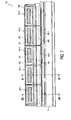
- the rail brake device 109 as shown in Figs 6A to 6C is of a type that is suitable for contactless cooperating with the rail 3 by the generation of eddy currents in the rail.
- the rail brake device 109 comprises a row of a plurality of magnetic circuits 111 which are identical in the embodiment shown, mutually coupled both mechanically and magnetically arranged behind one another in longitudinal direction.
- the structure of the magnetic rail brake device 109 will first be discussed with reference to the section VI-VI according to Fig. 6B through the centre of one of the magnetic circuits 111, see Fig. 6C .
- the magnetic circuit 111 in essence has the form of an E with two side parts having a free end and a intermediate part extending in between.
- the side parts of the E form soft-magnetic side-pole parts 113.1 and 113.2 and the intermediate part forms a soft-magnetic middle-pole part 115.
- the side-pole parts 113.1 and 113.2 have free ends 117.1 and 117.2 and the middle-pole part 115 has one free end 119 that extends to beyond the free ends 117.1 and 117.2. This free end 119 forms a partial working area of the joint working area of the rail brake device.
- Abutting on and as an extension to each middle-pole part 115 is a core 121 within a coil 125, which core 121 is located on the side opposite to the free end 119.
- the lasting permanent magnetic means surround the middle-pole parts 115.
- the magnetic circuit that is shown in a sectional view in Fig. 6C has four permanent magnets 123.1 and 123.2, see Fig. 6C , as well as 123.3 and 123.4, see Fig. 6B . In this case the middle-pole part 115 is surrounded by four separate permanent magnets.
- the permanent magnets such as the permanent magnets 123.1 to 123.4 surround the various middle-pole parts 115, in the row of magnetic circuits the permanent magnetic field generated by the permanent magnets alternately being directed inwardly to the centre of a middle-pole part 115 and radially outwardly from the center of the middle-pole part.
- the intermediate part of the E of each one of the various magnetic circuits 111 comprises cover means 127 in the form of a cover plate 127 of magnetisable material abutting on the side-pole parts 113.1 and 113.2 and on the core 121, which cover plate covers the coil parts 125 located opposite to the free ends of the relevant middle-pole parts 115. From Figs.
- the rail brake device also comprises closing short side walls 129.1 and 129.2 respectively which consist of magnetisable material and abut on the side-pole parts 113.1 and 113.2 shared by all magnetic circuits. These short sidewalls each form a part of the magnetic circuit with the nearest core 121.
- the various coils 125 arranged behind one another in longitudinal direction can be switched alternately in opposite directions.
- one of the magnetic polarity directions of the switchable core means develops the situation of Fig. 6A in which a plurality of in essence closed permanent magnetic fields are present which in essence extend within the row of magnetic circuits 111.
- a row of magnetic brake fields is present which extend beyond the working area 119 and as far as to within the rail 3.
- magnetic circuits are thought of having middle-pole parts 115 of square or rectangular section, around which four permanent magnets 123.1 to 123.4 are grouped.
- Such a shape is well-adapted to the block shape which the rail brake device in its totality has, so that a maximum amount of permanent magnetic material can be used.
- annularly closed permanent magnets such as for example square-shaped or rectangularly-shaped or having a different shape could also be thought of in lieu of separate permanent magnets.
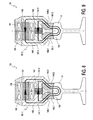
- the rail brake device 133 as shown in Figs. 7-9 is also of the type that is suitable for cooperating in a contactless manner with the rail 3 by the generation of eddy currents in the rail.
- the rail brake device 131 in this case comprises a row of five mutually mechanically coupled but not magnetically coupled individual rail brake devices arranged behind one another in longitudinal direction, alternately indicated by 131.1 and 131.2. These individual rail brake devices are essentially the same from a mechanical point of view, but the lastingly permanent magnetic means are alternately oppositely polarized.
- Fig. 8 shows a cross-sectional view along the arrows VIII-VIII in Fig. 7 of an individual rail brake device 131.1.
- the structure is equal to that of Figs. 2A-2B and comprises a magnetic circuit 133, coil means 135, core means 137, a working area 139, side-pole parts 141.1 and 141.2 having free ends 143.1 and 143.2 respectively, brake shoes 145.1 and 145.2 and lasting permanent magnetic means in the form of a permanent magnet 147 which is magnetized from left to right in the plane of the drawing.
- FIG. 9 of an individual rail brake device 131.2 are indicated by the reference numerals 149, 153, 155, 157.1-157.2, 159.1-159.2, 161.1-161.2 and 163 respectively.
- the permanent magnet 163 is magnetized in a direction opposite to the permanent magnet 147 shown in Fig. 8 .
- the operation of the individual rail brake devices 131.1 and 131.2 will not be further explained; with respect to these rail brake devices reference is made to the explanation of Figs. 2A-2B .
- the rail brake device 131 is covered in its entirety by a single cover extending over all individual rail brake devices 131.1 and 131.2. Plates of non-magnetisable suitable metal for the purposes of sealing, mutual connection for example by welding etc. are present between the individual rail brake devices on the bottom side thereof, on the sides and at the ends of the whole, which plates are not further shown in Fig. 7 .
- the total length of a rail brake device as shown in for example Figs. 2A to 2C or Fig. 7 may be for example 1200 to 1300 mm, with a height of about 160 mm and a width of about 130 mm.
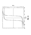
- Fig. 10 shows an example of the complete magnetic hysterisis curve of a hard-magnetic material that is suitable for the switchable permanent magnetic means of the various embodiments of the invention.
- the material is Alnico 600 which satisfies the characteristic features of claim 10.
- the Figure represents the connection between the magnetic induction B in kGauss (vertical axis) and the magnetic fieldstrength H in kOe (horizontal axis).
- the magnetization of the magnetic material The Figure shows for the material a magnetization of 12.6 kGauss or 1.26 Tesla and a coercive fieldstrength of .6 kOe or 48 kA/m.
Landscapes
- Engineering & Computer Science (AREA)
- Mechanical Engineering (AREA)
- Power Engineering (AREA)
- Transportation (AREA)
- Physics & Mathematics (AREA)
- Electromagnetism (AREA)
- Braking Arrangements (AREA)
- Dynamo-Electric Clutches, Dynamo-Electric Brakes (AREA)
- Regulating Braking Force (AREA)
Claims (15)
- Elektrisch betreibbare Magnetschienenbremse (1; 23; 53; 71; 89; 109; 131), die für das magnetische Zusammenwirken während eines Bremszustandes mit einer Schiene (3) aus magnetisierbarem Material vorgesehen ist und die Folgendes umfasst:• einen Magnetkreis (5; 25; 65; 73; 91; 111; 133; 149), der ein weichmagnetisches Material umfasst,• Spulenelemente (7; 27; 57; 79.1, 79.2; 103; 125; 135; 151) aus elektrisch leitendem Material zur Erzeugung eines elektromagnetischen Feldes, wenn ein elektrischer Strom durch diese hindurch fließt,• schaltbare magnetisierbare Kern-Elemente (9; 29; 55; 77.1, 77.2; 101; 121; 137; 153), welche einen Teil des Magnetkreises bilden und sich in den Spulenelementen (7; 27; 57; 79.1, 79.2; 103; 125; 135; 151) befinden, und• eine Bremsfläche (11; 31; 97.1, 97.2, 99; 119; 139; 155), die auf die Schiene (3) gerichtet werden soll, wobei während des Bremszustandes, infolge des Durchflusses eines elektrischen Stromes durch die Spulenelemente (7; 27; 57; 79.1, 79.2; 103; 125; 135; 151), ein magnetisches Bremsfeld eingeschaltet wird, das sich über die Bremsfläche (11; 31; 97.1, 97.2, 99; 119; 139; 155) hinaus erstreckt und das über die Schiene (3) geschlossen werden kann, dadurch gekennzeichnet, dass• die schaltbaren Kern-Elemente (9; 29; 55; 77.1, 77.2; 101; 121; 137; 153) ein hartmagnetisches Material umfassen,• infolge des Durchflusses wenigstens eines elektrischen Magnetisierungsimpulses geeigneter Dauer und Stärke durch die Spulenelemente (7; 27; 57; 79.1, 79.2; 103; 125; 135; 151) die schaltbaren Kern-Elemente (9; 29; 55; 77.1, 77.2; 101; 121; 137; 153) bis zu einem permanent magnetisierenden Zustand permanent magnetisierbar sind und• das magnetische Bremsfeld ein permanent magnetisches Bremsfeld umfasst, das in dem permanent magnetisierenden Zustand durch die schaltbaren Kern-Elemente (9; 29; 55; 77.1, 77.2; 101; 121; 137; 153) bereitgestellt wird.
- Magnetschienenbremse nach Anspruch 1, dadurch gekennzeichnet, dass• der Magnetkreis (5) in Querschnittsansicht im wesentlichen die Form eines U aufweist,• der Verbindungsteil des U das Kern-Element (9) aus hartmagnetischem Material umfasst und das Spulenelement (7) hält,• die Seitenteile des U weichmagnetische Seitenpolteile (15.1, 15.2), die an dem Kern-Element (9) anliegen, bilden und• der gegenüber den freien Enden der Seitenpolteile (15.1, 15.2) liegende Teil des Spulenelementes (7) durch ein Abdeckelement (19) aus nicht magnetisierbarem Material abgedeckt ist. [Fig. 1A - B].
- Magnetschienenbremse (23; 53; 71; 89; 109; 131) nach Anspruch 1, dadurch gekennzeichnet, dass• die Magnetschienenbremse weiterhin dauerhaft permanentmagnetische Elemente (33; 61.2, 61.2; 83; 105.1, 105.2; 123.1, 123.2, 123.3, 123.4) umfasst, welche ein dauerhaft permanentmagnetisches Feld erzeugen, das eine bestimmte magnetische Polarität aufweist,• der permanent magnetische Zustand der schaltbaren. Kern-Elemente (29; 55; 77.1, 77.2; 101; 121; 137; 153) in der Lage ist, eine erste magnetische Polaritätsrichtung und eine zweite, entgegen gesetzte, magnetische Polaritätsrichtung infolge von Stromimpulsen geeigneter elektrischer Polarität, die durch die Spulenelemente (27; 57; 79.1, 79.2; 103; 125; 135; 151) hindurch fließen, umzukehren und• in einer der magnetischen Polaritätsrichtungen der schaltbaren Kern-Elemente (29; 55; 77.1, 77.2; 101; 121; 137; 153) ein geschlossenes permanentmagnetisches Feld vorliegt, das sich im wesentlichen ausschließlich innerhalb des Magnetkreises (25; 65; 73; 91; 111; 133; 149) erstreckt, und dass in der anderen magnetischen Polaritätsrichtung das permanentmagnetische Bremsfeld bereitgestellt wird, welches sich über die Bremsfläche (31; 97.1, 97.2, 99; 119; 139; 155) hinaus erstreckt.
- Magnetschienenbremse (23) nach Anspruch 3, dadurch gekennzeichnet, dass• der Magnetkreis (25) in der Querschnittsansicht die Form eines U mit einem Verbindungsteil und angrenzenden Seitenteilen mit einem freien Ende aufweist (41.1, 41.2),• der Verbindungsteil des U das Kern-Element (29) aus hartmagnetischem Material umfasst und das Kern-Element hält,• die Seitenteile des U weichmagnetische Seitenpolteile (43.1, 43.2) bilden, welche an das Kern-Element angrenzen,• die dauerhaft permanentmagnetischen Elemente (33) zwischen den Seitenpolteilen (43.1, 43.2) und neben den Kern-Elementen (27) angeordnet sind und• der Teil des Kern-Elementes, der sich gegenüber den freien Enden (41.1, 41.2) der Seitenpolteile (43.1, 43.2) befindet, durch ein Abdeckelement (47) aus nicht magnetisierbarem Material abgedeckt ist. [Fig. 2A - C].
- Magnetschienenbremse (53) nach Anspruch 3, dadurch gekennzeichnet, dass• der Magnetkreis in Querschnittsansicht im wesentlichen die Form eines U aufweist, das einen Verbindungsteil und zwei angrenzende Seitenteile mit einem freien Ende aufweist,• der Verbindungsteil des U das Kern-Element (55) aus hartmagnetischem Material und das Spulenelement (57) umfasst,• die Seitenteile des U weichmagnetische Seitenpolteile (59.1, 59.2) bilden, welche an das Kern-Element (55) angrenzen,• das dauerhaft permanentmagnetische Element ein erstes und ein zweites dauerhaft permanentmagnetisches Element (61.1, 61.2) bilden, die sich an den Enden der mit dem Verbindungsteil verbundenen Seitenpolteile (59.1, 59.2) befinden, wobei sich diese Seitenpolteile an jeder der beiden Seiten des Spulenelementes (57) befinden,• das erste und das zweite dauerhaft permanentmagnetische Element (61.1, 61.2) entgegen gesetzte Polaritätsrichtungen aufweisen, die im wesentlichen parallel zu der Richtung der Seitenpolteile sind, und• der Zwischenteil des U ein Abdeckelement (63) aus magnetisierbarem Material umfasst, welches an das erste und das zweite dauerhaft permanentmagnetische Element (61.1, 61.2) angrenzt und den Teil des Spulenelementes (57) abdeckt, der sich gegenüber den freien Enden (69.1, 69.2) der Seitenpolteile (59.1, 59.2) befindet. [Fig. 3A - B]
- Magnetschienenbremse (71) nach Anspruch 3, dadurch gekennzeichnet, dass• der Magnetkreis (73) in Querschnittsansicht die Form eines U aufweist, das einen Verbindungsteil und zwei angrenzende Seitenteile mit einem freien Ende (75.1, 75.2) aufweist,• das Kern-Element ein erstes und ein zweites Kern-Element (77.1, 77.2) aus hartelastischem Material umfasst,• das Spulenelement ein erstes und ein zweites Spulenelement (79.1, 79.2) umfasst, die von dem ersten bzw. dem zweiten Kernelement getragen werden,• die Seitenteile des U jeweils einen weichmagnetischen Seitenpolteil (81.1, 81.2) bilden, welcher an einen der beiden Kern-Elemente angrenzt,• sich die Kern-Elemente (77.1, 77.2) jeweils im wesentlichen in Verlängerung eines Seitenpolteils (81.1, 81.2) erstrecken,• sich das dauerhaft permanentmagnetische Element (83) zwischen den Seitenpolteilen (81.1, 81.2) erstreckt und• der Zwischenteil des U ein Abdeckelement (63) aus magnetisierbarem Material umfasst, welches an das erste und das zweite Kern-Element (85) angrenzt und die Teile der Spulenelemente (79.1, 79.2) abdeckt, die sich gegenüber den freien Enden (75.1, 75.2) der Seitenpolteile befinden. [Fig. 4A - B]
- Magnetschienenbremse (89) nach Anspruch 3, dadurch gekennzeichnet, dass• der Magnetkreis (91) in Querschnittsansicht im wesentlichen die Form eines E aufweist, das einen Zwischenteil, zwei angrenzende Seitenteile mit einem freien Ende (97.1, 97.2) und einen sich dazwischen erstreckenden mittleren Teil mit einem freien Ende (99) umfasst,• die Seitenteile des E weichmagnetische Seitenpolteile (93.1, 93.2) umfassen,• der Zwischenteil des E einen weichmagnetischen Mittelpolteil (95) umfasst,• das Kern-Element (101) aus hartmagnetischem Material, welches an den Mittelpolteil (95) angrenzt und sich in Verlängerung desselben auf der dem freien Ende (99) gegenüberliegenden Seite erstreckt, in Form eines Kerns vorliegt, der das Spulenelement (103) trägt,• das dauerhaft permanentmagnetische Element ein erstes und ein zweites dauerhaft permanentmagnetisches Element (105.1, 105.2) auf den beiden Seiten des Mittelpolteils (95) umfasst, und zwar jeweils eines zwischen dem Mittelpolteil (95) und einem Seitenpolteil (93.1, 93.2), und• der Zwischenteil des E ein Abdeckelement (107) aus magnetisierbarem Material umfasst, das an die Seitenpolteile (93.1, 93.2) und an den Kern (101) angrenzt und den Teil des Spulenelementes abdeckt, der sich gegenüber dem freien Ende (99) des Mittelpolteils (95) befindet. [Fig. 5A - B] .
- Magnetschienenbremse (109) nach Anspruch 3, eines Typs, der für das Zusammenwirken der Bremsfläche mit einer Oberfläche der Schiene (3) geeignet ist, wobei diese Flächen aufgrund der Erzeugung von Wirbelströmen in der Schiene durch eine Luftspalte voneinander getrennt sind, dadurch gekennzeichnet, dass• die Magnetschienenbremse (109) eine Reihe aus einer Mehrzahl von im wesentlichen identischen, miteinander mechanisch und magnetisch gekoppelten Magnetkreisen (111) umfasst, welche hintereinander in Längsrichtung angeordnet sind,• jeder einzelne der Magnetkreise (111) in Querschnittsansicht im wesentlichen die Form eines E aufweist, welches einen Zwischenteil, zwei angrenzende seitliche Teile mit einem freien Ende (117.1, 117.2) und einen sich dazwischen erstreckenden mittleren Teil mit einem freien Ende (119), das sich bis zu den freien Enden (117.1, 117.2) der Seitenteile erstreckt, umfasst,• die Seitenteile jedes E weichmagnetische Seitenpolteile (113.1, 113.2) bilden,• der mittlere Teil jedes E einen weichmagnetischen Mittelpolteil (115) umfasst, welcher am freien Ende (119) eine partielle Bremsfläche bildet,• die partiellen Bremsflächen der einzelnen Es zusammen die Bremsfläche der Magnetschienenbremse bilden,• die Kern-Elemente (121) aus hartmagnetischem Material, welche an jeden einzelnen Mittelpolteil (115) angrenzen und sich in Verlängerung dieser Mittelpolteile auf der dem freien Ende (119) gegenüberliegenden Seite erstrecken, in Form eines Kerns vorliegen, welcher das Spulenelement (125) trägt,• die dauerhaft permanentmagnetischen Elemente (123.1, 123.2, 123.3, 123.4) die einzelnen Mittelpolteile (115) umgeben und in der Reihe der Magnetkreise das von den permanentmagnetischen Elementen erzeugte permanentmagnetische Feld abwechselnd radial nach innen, zum Zentrum eines Mittelpolteils, oder vom Zentrum des Mittenpolteils aus radial nach außen gerichtet ist,• der Zwischenteil des E jedes einzelnen der Magnetkreise (111) ein Abdeckelement (127) aus magnetisierbarem Material umfasst, das an die Seitenpolteile (113.1, 113.2) und an den Kern angrenzt und den Teil der Spulenelemente abdeckt, der sich gegenüber dem freien Ende des betreffenden Mittelpolteils (115) befindet,• die einzelnen hintereinander angeordneten Spulenelemente (125) die abwechselnde Umschaltung derselben in entgegen gesetzte Richtungen erlauben, so dass in einer der magnetischen Polaritätsrichtungen der schaltbaren Kern-Elemente (121) eine Vielzahl von im wesentlichen geschlossenen permanentmagnetischen Feldern vorliegt, die sich im wesentlichen ausschließlich innerhalb der Reihe von Magnetkreisen (111) erstrecken, und in der anderen magnetischen Polaritätsrichtung eine Reihe permanentmagnetischer Bremsfelder entgegen gesetzter Polarität vorhanden ist, welche sich über die Bremsfläche hinaus erstrecken (119). [Fig. 6A - C].
- Magnetschienenbremse (131) nach Anspruch 3, eines Typs, der sich für das Zusammenwirken der Bremsfläche mit einer Fläche der Schiene (3) eignet, wobei diese Flächen durch einen Luftspalt, der infolge der Erzeugung von Wirbelströmen in der Schiene entsteht, getrennt sind, dadurch gekennzeichnet, dass die Magnetschienenbremse (131) eine Reihe aus einer Mehrzahl von miteinander mechanisch gekoppelten, einzelnen Magnetschienenbremsen (133) umfasst, die in Längsrichtung hintereinander angeordnet sind. [Fig. 7 - 9]
- Magnetschienenbremse nach einem der vorhergehenden Ansprüche, dadurch gekennzeichnet, dass• das hartmagnetische Material der schaltbaren Kern-Elemente im permanentmagnetisierenden Zustand eine Koerzitivfeldstärke aufweist, die größer ist als 35 kA/m und• die dauerhaften permanentmagnetischen Elemente eine Koerzitivfeldstärke aufweisen, deren Wert wesentlich höher liegt.
- Magnetschienenbremse nach einem der vorhergehenden Ansprüche, dadurch gekennzeichnet, dass• die Magnetschienenbremse gegen die Durchleitung eines Heizstroms durch die Spulenelemente über eine relativ lange Zeitspanne hinweg beständig ist, welcher einer Eisbildung auf dem Äußeren der Magnetschienenbremse entgegenwirken soll.
- Magnetschienenbremse nach einem der vorhergehenden Ansprüche; dadurch gekennzeichnet, dass die Außenkontur des Querschnitts innerhalb eines 130 x 160 mm großen Rechtecks liegt.
- Magnetschienenbremse nach einem der vorhergehenden Ansprüche, dadurch gekennzeichnet, dass• die Magnetschienenbremse federnd aufgehängt ist und• es die Magnetschienenbremse erlaubt, diese aus einem Ruhezustand in einem Abstand von der Schiene herauszubewegen, und zwar infolge eines elektrischen Stromimpulses, der aufgrund einer magnetischen Kraft durch die Spulenelemente fließt.
- Magnetschienenbremse nach einem der vorhergehenden Ansprüche, dadurch gekennzeichnet, dass diese gegen das Fließen eines Notfall-Bremsstroms durch die Spulenelemente beständig ist, der das magnetische Bremsfeld, welches die Bremskraft erhöhen soll, während der Verwendung der Magnetschienenbremse als Notfallbremse verstärkt.
- Anordnung, die entlang einer oder mehrerer Schienen beweglich ist, wie zum Beispiel ein Schienenfahrzeug, ein Aufzug, eine Hebevorrichtung etc., dadurch gekennzeichnet, dass die Anordnung eine elektrisch betreibbare Magnetschienenbremse (1; 23; 53; 71; 89; 109; 131) nach einem oder mehreren der vorhergehenden Ansprüche 1 - 14 umfasst.
Applications Claiming Priority (2)
| Application Number | Priority Date | Filing Date | Title |
|---|---|---|---|
| NL1022885A NL1022885C2 (nl) | 2003-03-10 | 2003-03-10 | Elektrisch bedienbare magnetische railreminrichting, alsmede langs een of meer rails beweegbare inrichting voorzien van een railreminrichting. |
| NL1022885 | 2003-03-10 |
Publications (3)
| Publication Number | Publication Date |
|---|---|
| EP1477382A2 EP1477382A2 (de) | 2004-11-17 |
| EP1477382A3 EP1477382A3 (de) | 2004-12-01 |
| EP1477382B1 true EP1477382B1 (de) | 2009-06-24 |
Family
ID=33029097
Family Applications (1)
| Application Number | Title | Priority Date | Filing Date |
|---|---|---|---|
| EP04075755A Expired - Lifetime EP1477382B1 (de) | 2003-03-10 | 2004-03-08 | elektrisch bedienbare magnetische Schienenfahrzeugbremse |
Country Status (4)
| Country | Link |
|---|---|
| EP (1) | EP1477382B1 (de) |
| AT (1) | ATE434553T1 (de) |
| DE (1) | DE602004021657D1 (de) |
| NL (1) | NL1022885C2 (de) |
Cited By (2)
| Publication number | Priority date | Publication date | Assignee | Title |
|---|---|---|---|---|
| CN103717473A (zh) * | 2011-07-28 | 2014-04-09 | 克诺尔-布里姆斯股份有限公司 | 用于给轨道车辆的轨道制动器的至少一个电线圈施加至少一个电脉冲的装置 |
| RU2603431C1 (ru) * | 2015-09-02 | 2016-11-27 | Общество с ограниченной ответственностью "КРУГ" | Способ изготовления или ремонта катушки рельсового тормоза и катушка рельсового тормоза |
Families Citing this family (12)
| Publication number | Priority date | Publication date | Assignee | Title |
|---|---|---|---|---|
| DE102007014717B3 (de) * | 2007-03-23 | 2008-11-27 | Knorr-Bremse Systeme für Schienenfahrzeuge GmbH | Magnetschienenbremsvorrichtung mit asymmetrischer Erregerspule und/oder mit mehrteiliger Spule |
| CN102556102B (zh) * | 2012-01-17 | 2014-08-20 | 江苏大学 | 一种电磁式磁轨制动器及其控制方法 |
| CN102923159B (zh) * | 2012-10-24 | 2015-09-30 | 江苏大学 | 一种电磁式磁轨制动器 |
| CN103000327A (zh) * | 2012-10-31 | 2013-03-27 | 镇江电磁设备厂有限责任公司 | 一种磁轨制动电磁铁 |
| CN102951172B (zh) * | 2012-11-14 | 2015-03-04 | 江苏大学 | 一种侧滑式磁轨制动器增力装置 |
| CN104002832A (zh) * | 2014-06-10 | 2014-08-27 | 青岛四方车辆研究所有限公司 | 磁轨制动器用隔板 |
| CN104494635A (zh) * | 2014-11-24 | 2015-04-08 | 上海庞丰交通设备科技有限公司 | 单磁式永磁轨道制动装置 |
| CN104494634A (zh) * | 2014-11-24 | 2015-04-08 | 上海庞丰交通设备科技有限公司 | 双磁式永磁轨道制动装置 |
| CN105151077A (zh) * | 2015-08-21 | 2015-12-16 | 青岛四方车辆研究所有限公司 | 带有水平布置励磁线圈的轨道交通磁轨制动器 |
| CN109649179B (zh) * | 2019-02-20 | 2021-11-02 | 扬州大学 | 一种组合式电磁涡流制动装置 |
| CN114407964B (zh) * | 2022-01-21 | 2023-10-31 | 中车青岛四方机车车辆股份有限公司 | 磁轨制动装置及轨道车辆 |
| CN116353653A (zh) * | 2023-03-03 | 2023-06-30 | 宁波国创机车装备有限公司 | 一种磁轨制动电磁铁及磁轨制动器 |
Family Cites Families (9)
| Publication number | Priority date | Publication date | Assignee | Title |
|---|---|---|---|---|
| FR2333612A1 (fr) | 1975-12-04 | 1977-07-01 | Braillon P | Plateau magnetique a aimants permanents et electro-permanents |
| IT1212127B (it) | 1986-07-28 | 1989-11-08 | Cardone Tecnomagnetica | Apparecchiatura magnetopermanente di ancoraggio. |
| DE9208380U1 (de) | 1992-06-23 | 1992-08-13 | Knorr-Bremse AG, 8000 München | Magnetschienenbremse |
| NL9402145A (nl) * | 1994-12-16 | 1996-08-01 | Transferia Systems Bv | Magnetische railreminrichting. |
| NL1001332C2 (nl) * | 1995-10-03 | 1997-04-04 | Transferia Systems Bv | Railreminrichting met permanent magnetische bekrachtiging. |
| DE19619409C2 (de) * | 1996-05-14 | 2001-02-15 | Ruefas Pagid Ag | Magnetschienenbremse |
| US6104270A (en) | 1997-08-04 | 2000-08-15 | Railfix N.V. | Lifter with electropermanent magnets provided with a safety device |
| DE19943091C2 (de) * | 1999-09-09 | 2001-08-09 | Daimler Chrysler Ag | Permanent-Magnetschienenbremse |
| DE10008052A1 (de) * | 2000-02-22 | 2001-09-06 | Siemens Ag | Permanentmagnetisch erregte Wirbelstrombremse |
-
2003
- 2003-03-10 NL NL1022885A patent/NL1022885C2/nl not_active IP Right Cessation
-
2004
- 2004-03-08 DE DE602004021657T patent/DE602004021657D1/de not_active Expired - Lifetime
- 2004-03-08 EP EP04075755A patent/EP1477382B1/de not_active Expired - Lifetime
- 2004-03-08 AT AT04075755T patent/ATE434553T1/de active
Cited By (3)
| Publication number | Priority date | Publication date | Assignee | Title |
|---|---|---|---|---|
| CN103717473A (zh) * | 2011-07-28 | 2014-04-09 | 克诺尔-布里姆斯股份有限公司 | 用于给轨道车辆的轨道制动器的至少一个电线圈施加至少一个电脉冲的装置 |
| CN103717473B (zh) * | 2011-07-28 | 2016-08-17 | 克诺尔-布里姆斯股份有限公司 | 用于给轨道车辆的轨道制动器的至少一个电线圈施加至少一个电脉冲的装置 |
| RU2603431C1 (ru) * | 2015-09-02 | 2016-11-27 | Общество с ограниченной ответственностью "КРУГ" | Способ изготовления или ремонта катушки рельсового тормоза и катушка рельсового тормоза |
Also Published As
| Publication number | Publication date |
|---|---|
| DE602004021657D1 (de) | 2009-08-06 |
| EP1477382A3 (de) | 2004-12-01 |
| ATE434553T1 (de) | 2009-07-15 |
| EP1477382A2 (de) | 2004-11-17 |
| NL1022885C2 (nl) | 2004-09-13 |
Similar Documents
| Publication | Publication Date | Title |
|---|---|---|
| EP1477382B1 (de) | elektrisch bedienbare magnetische Schienenfahrzeugbremse | |
| JP5151882B2 (ja) | 渦電流式レールブレーキ | |
| US8033365B2 (en) | Magnetic rail brake device with asymmetric excitation coils and/or with multi-part coils | |
| US4122922A (en) | Infinitely variable wear-free eddy current and/or hysteresis brake, preferably for track-bound vehicles | |
| CN100425490C (zh) | 磁轨制动器 | |
| GB1305519A (de) | ||
| CN103481794B (zh) | 一种中低速磁浮列车用组合式悬浮电磁铁及制作方法 | |
| CN100396527C (zh) | 磁轨制动器 | |
| CN1461096A (zh) | 永磁和电磁混合励磁的长定子直线同步电机 | |
| US20140246277A1 (en) | Device for applying at least one electrical pulse to at least one electrical coil of a track brake of a rail vehicle | |
| Yamamura et al. | Electromagnetic levitation system by means of salient-pole type magnets coupled with laminated slotless rails | |
| JPH077812A (ja) | 超伝導磁石を使用する電磁懸架装置 | |
| RU2185984C2 (ru) | Рельсовый тормоз с постоянными магнитами | |
| CN101699730B (zh) | 汽车用混合型涡流缓速器 | |
| RU2216471C2 (ru) | Электромагнитный рельсовый тормоз | |
| JPH09224366A (ja) | リニアモータ | |
| CN115195806A (zh) | 一种电涡流-磁轨复合制动器 | |
| SU1202944A1 (ru) | Электромагнитный замедлитель | |
| RU2192980C2 (ru) | Электромагнитный рельсовый тормоз | |
| RU2200103C2 (ru) | Устройство для увеличения сцепления колес локомотива с рельсами | |
| CA1185904A (en) | Magnetic brake shoe | |
| AU2012227285B2 (en) | Magnetic rail brake device with asymmetric excitation coils and/or with multi-part coils | |
| GB2633725A (en) | Magnet system for a railway advanced warning system | |
| JPH0529285U (ja) | 磁気回路 | |
| HK1194335B (en) | Device for applying at least one electrical pulse to at least one electrical coil of a track brake of a rail vehicle |
Legal Events
| Date | Code | Title | Description |
|---|---|---|---|
| PUAI | Public reference made under article 153(3) epc to a published international application that has entered the european phase |
Free format text: ORIGINAL CODE: 0009012 |
|
| PUAL | Search report despatched |
Free format text: ORIGINAL CODE: 0009013 |
|
| AK | Designated contracting states |
Kind code of ref document: A2 Designated state(s): AT BE BG CH CY CZ DE DK EE ES FI FR GB GR HU IE IT LI LU MC NL PL PT RO SE SI SK TR |
|
| AX | Request for extension of the european patent |
Extension state: AL HR LT LV MK |
|
| AK | Designated contracting states |
Kind code of ref document: A3 Designated state(s): AT BE BG CH CY CZ DE DK EE ES FI FR GB GR HU IE IT LI LU MC NL PL PT RO SE SI SK TR |
|
| AX | Request for extension of the european patent |
Extension state: AL HR LT LV MK |
|
| 17P | Request for examination filed |
Effective date: 20050601 |
|
| AKX | Designation fees paid |
Designated state(s): AT BE BG CH CY CZ DE DK EE ES FI FR GB GR HU IE IT LI LU MC NL PL PT RO SE SI SK TR |
|
| TPAC | Observations filed by third parties |
Free format text: ORIGINAL CODE: EPIDOSNTIPA |
|
| GRAP | Despatch of communication of intention to grant a patent |
Free format text: ORIGINAL CODE: EPIDOSNIGR1 |
|
| GRAS | Grant fee paid |
Free format text: ORIGINAL CODE: EPIDOSNIGR3 |
|
| GRAA | (expected) grant |
Free format text: ORIGINAL CODE: 0009210 |
|
| AK | Designated contracting states |
Kind code of ref document: B1 Designated state(s): AT BE BG CH CY CZ DE DK EE ES FI FR GB GR HU IE IT LI LU MC NL PL PT RO SE SI SK TR |
|
| REG | Reference to a national code |
Ref country code: GB Ref legal event code: FG4D |
|
| REG | Reference to a national code |
Ref country code: CH Ref legal event code: EP |
|
| REG | Reference to a national code |
Ref country code: IE Ref legal event code: FG4D |
|
| REF | Corresponds to: |
Ref document number: 602004021657 Country of ref document: DE Date of ref document: 20090806 Kind code of ref document: P |
|
| PG25 | Lapsed in a contracting state [announced via postgrant information from national office to epo] |
Ref country code: FI Free format text: LAPSE BECAUSE OF FAILURE TO SUBMIT A TRANSLATION OF THE DESCRIPTION OR TO PAY THE FEE WITHIN THE PRESCRIBED TIME-LIMIT Effective date: 20090624 |
|
| PG25 | Lapsed in a contracting state [announced via postgrant information from national office to epo] |
Ref country code: SE Free format text: LAPSE BECAUSE OF FAILURE TO SUBMIT A TRANSLATION OF THE DESCRIPTION OR TO PAY THE FEE WITHIN THE PRESCRIBED TIME-LIMIT Effective date: 20090924 Ref country code: PL Free format text: LAPSE BECAUSE OF FAILURE TO SUBMIT A TRANSLATION OF THE DESCRIPTION OR TO PAY THE FEE WITHIN THE PRESCRIBED TIME-LIMIT Effective date: 20090624 Ref country code: SI Free format text: LAPSE BECAUSE OF FAILURE TO SUBMIT A TRANSLATION OF THE DESCRIPTION OR TO PAY THE FEE WITHIN THE PRESCRIBED TIME-LIMIT Effective date: 20090624 |
|
| NLV1 | Nl: lapsed or annulled due to failure to fulfill the requirements of art. 29p and 29m of the patents act | ||
| PG25 | Lapsed in a contracting state [announced via postgrant information from national office to epo] |
Ref country code: EE Free format text: LAPSE BECAUSE OF FAILURE TO SUBMIT A TRANSLATION OF THE DESCRIPTION OR TO PAY THE FEE WITHIN THE PRESCRIBED TIME-LIMIT Effective date: 20090624 Ref country code: ES Free format text: LAPSE BECAUSE OF FAILURE TO SUBMIT A TRANSLATION OF THE DESCRIPTION OR TO PAY THE FEE WITHIN THE PRESCRIBED TIME-LIMIT Effective date: 20091005 |
|
| PG25 | Lapsed in a contracting state [announced via postgrant information from national office to epo] |
Ref country code: NL Free format text: LAPSE BECAUSE OF FAILURE TO SUBMIT A TRANSLATION OF THE DESCRIPTION OR TO PAY THE FEE WITHIN THE PRESCRIBED TIME-LIMIT Effective date: 20090624 Ref country code: SK Free format text: LAPSE BECAUSE OF FAILURE TO SUBMIT A TRANSLATION OF THE DESCRIPTION OR TO PAY THE FEE WITHIN THE PRESCRIBED TIME-LIMIT Effective date: 20090624 Ref country code: BE Free format text: LAPSE BECAUSE OF FAILURE TO SUBMIT A TRANSLATION OF THE DESCRIPTION OR TO PAY THE FEE WITHIN THE PRESCRIBED TIME-LIMIT Effective date: 20090624 |
|
| PG25 | Lapsed in a contracting state [announced via postgrant information from national office to epo] |
Ref country code: PT Free format text: LAPSE BECAUSE OF FAILURE TO SUBMIT A TRANSLATION OF THE DESCRIPTION OR TO PAY THE FEE WITHIN THE PRESCRIBED TIME-LIMIT Effective date: 20091024 Ref country code: BG Free format text: LAPSE BECAUSE OF FAILURE TO SUBMIT A TRANSLATION OF THE DESCRIPTION OR TO PAY THE FEE WITHIN THE PRESCRIBED TIME-LIMIT Effective date: 20090924 |
|
| PG25 | Lapsed in a contracting state [announced via postgrant information from national office to epo] |
Ref country code: DK Free format text: LAPSE BECAUSE OF FAILURE TO SUBMIT A TRANSLATION OF THE DESCRIPTION OR TO PAY THE FEE WITHIN THE PRESCRIBED TIME-LIMIT Effective date: 20090624 |
|
| PLBE | No opposition filed within time limit |
Free format text: ORIGINAL CODE: 0009261 |
|
| STAA | Information on the status of an ep patent application or granted ep patent |
Free format text: STATUS: NO OPPOSITION FILED WITHIN TIME LIMIT |
|
| 26N | No opposition filed |
Effective date: 20100325 |
|
| PG25 | Lapsed in a contracting state [announced via postgrant information from national office to epo] |
Ref country code: MC Free format text: LAPSE BECAUSE OF NON-PAYMENT OF DUE FEES Effective date: 20100331 Ref country code: GR Free format text: LAPSE BECAUSE OF FAILURE TO SUBMIT A TRANSLATION OF THE DESCRIPTION OR TO PAY THE FEE WITHIN THE PRESCRIBED TIME-LIMIT Effective date: 20090925 |
|
| REG | Reference to a national code |
Ref country code: CH Ref legal event code: PL |
|
| PG25 | Lapsed in a contracting state [announced via postgrant information from national office to epo] |
Ref country code: IE Free format text: LAPSE BECAUSE OF NON-PAYMENT OF DUE FEES Effective date: 20100308 |
|
| PG25 | Lapsed in a contracting state [announced via postgrant information from national office to epo] |
Ref country code: LI Free format text: LAPSE BECAUSE OF NON-PAYMENT OF DUE FEES Effective date: 20100331 Ref country code: CH Free format text: LAPSE BECAUSE OF NON-PAYMENT OF DUE FEES Effective date: 20100331 |
|
| REG | Reference to a national code |
Ref country code: DE Ref legal event code: R082 Ref document number: 602004021657 Country of ref document: DE Representative=s name: FLACCUS MUELLER-WOLFF, DE Effective date: 20110629 Ref country code: DE Ref legal event code: R081 Ref document number: 602004021657 Country of ref document: DE Owner name: KNORR-BREMSE GMBH, AT Free format text: FORMER OWNER: WALKER EUROPE HOLDING B.V., BLADEL, NL Effective date: 20110629 |
|
| REG | Reference to a national code |
Ref country code: GB Ref legal event code: 732E Free format text: REGISTERED BETWEEN 20111013 AND 20111019 |
|
| REG | Reference to a national code |
Ref country code: FR Ref legal event code: TP Owner name: KNORR-BREMSE GMBH, AT Effective date: 20111011 |
|
| REG | Reference to a national code |
Ref country code: AT Ref legal event code: PC Ref document number: 434553 Country of ref document: AT Kind code of ref document: T Owner name: KNORR-BREMSE GMBH, AT Effective date: 20120105 |
|
| PG25 | Lapsed in a contracting state [announced via postgrant information from national office to epo] |
Ref country code: CY Free format text: LAPSE BECAUSE OF FAILURE TO SUBMIT A TRANSLATION OF THE DESCRIPTION OR TO PAY THE FEE WITHIN THE PRESCRIBED TIME-LIMIT Effective date: 20090624 |
|
| PG25 | Lapsed in a contracting state [announced via postgrant information from national office to epo] |
Ref country code: LU Free format text: LAPSE BECAUSE OF NON-PAYMENT OF DUE FEES Effective date: 20100308 Ref country code: HU Free format text: LAPSE BECAUSE OF FAILURE TO SUBMIT A TRANSLATION OF THE DESCRIPTION OR TO PAY THE FEE WITHIN THE PRESCRIBED TIME-LIMIT Effective date: 20091225 |
|
| PG25 | Lapsed in a contracting state [announced via postgrant information from national office to epo] |
Ref country code: TR Free format text: LAPSE BECAUSE OF FAILURE TO SUBMIT A TRANSLATION OF THE DESCRIPTION OR TO PAY THE FEE WITHIN THE PRESCRIBED TIME-LIMIT Effective date: 20090624 |
|
| PG25 | Lapsed in a contracting state [announced via postgrant information from national office to epo] |
Ref country code: RO Free format text: LAPSE BECAUSE OF FAILURE TO SUBMIT A TRANSLATION OF THE DESCRIPTION OR TO PAY THE FEE WITHIN THE PRESCRIBED TIME-LIMIT Effective date: 20090624 |
|
| REG | Reference to a national code |
Ref country code: FR Ref legal event code: PLFP Year of fee payment: 13 |
|
| PGFP | Annual fee paid to national office [announced via postgrant information from national office to epo] |
Ref country code: IT Payment date: 20160318 Year of fee payment: 13 |
|
| REG | Reference to a national code |
Ref country code: FR Ref legal event code: PLFP Year of fee payment: 14 |
|
| PG25 | Lapsed in a contracting state [announced via postgrant information from national office to epo] |
Ref country code: IT Free format text: LAPSE BECAUSE OF NON-PAYMENT OF DUE FEES Effective date: 20170308 |
|
| REG | Reference to a national code |
Ref country code: FR Ref legal event code: PLFP Year of fee payment: 15 |
|
| PGFP | Annual fee paid to national office [announced via postgrant information from national office to epo] |
Ref country code: GB Payment date: 20180326 Year of fee payment: 15 Ref country code: DE Payment date: 20180322 Year of fee payment: 15 Ref country code: CZ Payment date: 20180222 Year of fee payment: 15 |
|
| PGFP | Annual fee paid to national office [announced via postgrant information from national office to epo] |
Ref country code: FR Payment date: 20180326 Year of fee payment: 15 Ref country code: AT Payment date: 20180320 Year of fee payment: 15 |
|
| REG | Reference to a national code |
Ref country code: DE Ref legal event code: R119 Ref document number: 602004021657 Country of ref document: DE |
|
| PG25 | Lapsed in a contracting state [announced via postgrant information from national office to epo] |
Ref country code: CZ Free format text: LAPSE BECAUSE OF NON-PAYMENT OF DUE FEES Effective date: 20190308 |
|
| REG | Reference to a national code |
Ref country code: AT Ref legal event code: MM01 Ref document number: 434553 Country of ref document: AT Kind code of ref document: T Effective date: 20190308 |
|
| GBPC | Gb: european patent ceased through non-payment of renewal fee |
Effective date: 20190308 |
|
| PG25 | Lapsed in a contracting state [announced via postgrant information from national office to epo] |
Ref country code: AT Free format text: LAPSE BECAUSE OF NON-PAYMENT OF DUE FEES Effective date: 20190308 Ref country code: DE Free format text: LAPSE BECAUSE OF NON-PAYMENT OF DUE FEES Effective date: 20191001 Ref country code: GB Free format text: LAPSE BECAUSE OF NON-PAYMENT OF DUE FEES Effective date: 20190308 |
|
| PG25 | Lapsed in a contracting state [announced via postgrant information from national office to epo] |
Ref country code: FR Free format text: LAPSE BECAUSE OF NON-PAYMENT OF DUE FEES Effective date: 20190331 |