EP1477439A1 - Dispositif pour transférer des objets - Google Patents
Dispositif pour transférer des objets Download PDFInfo
- Publication number
- EP1477439A1 EP1477439A1 EP04011489A EP04011489A EP1477439A1 EP 1477439 A1 EP1477439 A1 EP 1477439A1 EP 04011489 A EP04011489 A EP 04011489A EP 04011489 A EP04011489 A EP 04011489A EP 1477439 A1 EP1477439 A1 EP 1477439A1
- Authority
- EP
- European Patent Office
- Prior art keywords
- cylinder
- piston
- suction device
- cylinder piston
- guide element
- Prior art date
- Legal status (The legal status is an assumption and is not a legal conclusion. Google has not performed a legal analysis and makes no representation as to the accuracy of the status listed.)
- Granted
Links
Images





Classifications
-
- B—PERFORMING OPERATIONS; TRANSPORTING
- B65—CONVEYING; PACKING; STORING; HANDLING THIN OR FILAMENTARY MATERIAL
- B65G—TRANSPORT OR STORAGE DEVICES, e.g. CONVEYORS FOR LOADING OR TIPPING, SHOP CONVEYOR SYSTEMS OR PNEUMATIC TUBE CONVEYORS
- B65G47/00—Article or material-handling devices associated with conveyors; Methods employing such devices
- B65G47/74—Feeding, transfer, or discharging devices of particular kinds or types
- B65G47/90—Devices for picking-up and depositing articles or materials
- B65G47/91—Devices for picking-up and depositing articles or materials incorporating pneumatic, e.g. suction, grippers
Definitions
- the invention relates to a device for implementing Objects, such as workpieces, components or the like, with at least one on the surface of the object attachable, acting like a suction cup and with Vacuum suction device.
- the device technology is particularly disadvantageous and consequently financially expensive operation known devices using expensive vacuum pumps, what additional components such as connectors with Vacuum threads, vacuum hoses, vacuum valves and the like require.
- the vacuum technology used shows also a relatively high energy requirement during operation on.
- the invention has for its object a device of the type mentioned at the outset in such a way that it makes the use of vacuum pumps unnecessary.
- this object is achieved with a device of the type mentioned in that the suction device with at least part of the interior of one Printing cylinder is connected, in which at least a cylinder piston sealed against the inside of the cylinder slidably arranged in the longitudinal direction of the printing cylinder is, with the cylinder piston preloaded in this way is that it corresponds to the suction device Cylinder space is striving to enlarge in this with the suction device corresponding cylinder chamber negative pressure to create.
- Cylinder pistons in the sense of the invention are both conventional, pistons displaceable in a cylinder tube as also membranes as well as any other means meant, which with an axial displacement along the longitudinal axis of the cylinder to generate negative pressure are.
- An advantageous design in terms of construction technology provides that the one corresponding to the suction device Cylinder chamber on the suction device facing Side of the cylinder piston and the cylinder piston in the direction of that facing away from the suction device End of the pressure cylinder is preloaded.
- the cylinder piston in Direction of the side of the suction device facing away is the cylinder piston in Direction of the side of the suction device facing away Printing cylinder preloaded to after moving the cylinder piston against its direction of preload purely mechanical the cylinder space corresponding to the suction device to enlarge and consequently on the one to be implemented Object attached suction device vacuum to create.
- cylinder piston against its bias direction using fluid pressure, i.e. pneumatic, hydropneumatic or hydraulically, is displaceable.
- fluid pressure i.e. pneumatic, hydropneumatic or hydraulically
- the cylinder piston is preferably pneumatically displaceable, which in particular for cost reasons e.g. done with compressed air can.
- the Cylinder piston magnetic against its direction of preload is movable.
- the cylinder piston can and / or a piston rod connected to this a permanent magnet wear, which with a to the extent of the Cylinder arranged electromagnets, especially one Coil, interacts.
- the cylinder piston and / or a piston rod connected to it an electromagnet, in particular a coil, carries, which with a arranged around the circumference of the cylinder Permanent magnet interacts.
- the cylinder piston is preferably preloaded elastically, which is particularly simple and inexpensive in particular happen by means of at least one coil spring can.
- the use of a coil spring for elastic preload the cylinder piston also provides for an essentially trouble-free and wear-free operation of the transfer device and also allows adjustment of the maximum possible applied to the suction device Vacuum by using different coil springs Spring constant.
- the achievable vacuum is over the better or the achievable vacuum the lower, ever the spring constant of the coil spring is selected to be larger and consequently the greater the spring force on the cylinder piston preload caused.
- an air filter in particular a vacuum filter is arranged.
- a preferred embodiment provides that the suction device stationary on the pressure cylinder, in particular on one Cylinder cover is arranged.
- the cylinder cover shows in in this case the suction device with the one facing it Through hole connecting the interior of the pressure cylinder on, facing away from the impression cylinder End the suction device fluid-tight, possibly under Interposition of an air filter is attached.
- the cylinder piston preferably by means of a piston rod attached to this guided, the piston rod preferably one on the arranged end of the pressure cylinder facing away from the suction device Intermediate cylinder bottom and on this essentially is stored in a fluid-tight manner.
- the piston rod on its the End facing away from the cylinder piston has a collar, wherein the coil spring preloading the cylinder piston between the cylinder bottom and the collar acts.
- the federal government can in particular displaceable in the longitudinal direction of the piston rod be set on the piston rod to the preload of the Coil spring and thus the elastic preload of the To be able to adjust the cylinder piston.
- the between Cylinder piston and the cylinder chamber arranged cylinder bottom has a fluid connection to the cylinder piston against its preload by means of the coil spring through a pressure fluid introduced into this cylinder space to relocate.
- the fluid connection is useful with a Actuator, especially a control valve via which the cylinder space assigned to this fluid connection is connectable to a source of pressurized fluid.
- a fluid connection which also equipped with an actuator, in particular a control valve can be, for example, that on the suction device adjacent, purely mechanical by means of the coil spring monitor or adjust the vacuum generated.
- the transfer device according to the invention looks in preferred embodiment that the suction device on the passing through the cylinder cover and on the cylinder cover in essential fluid-tight piston rod telescopic is arranged.
- Such a configuration has in particular the advantage that the printing cylinder with respect of the objects to be implemented at approximately the same level can be held, the piston rod with the Suction device for gripping an object from the Printing cylinder can be moved out.
- the telescopic piston rod at its end facing away from the suction device a guide element mounted on its the piston rod or the side facing away from the suction device communicates with the cylinder piston and in the direction of this path is biased.
- the preload on the cylinder piston is preferred for the reasons mentioned in an elastic way by means of a coil spring, which between the guide element and the cylinder piston acts. In this way it is for purely mechanical production of the vacuum to be applied to the suction device serving cylinder piston over the coil spring with the Guide element connected and elastically preloaded away from this.
- a further fluid connection which is also preferred with an actuator, in particular with a control valve, is equipped to this cylinder space Extension of the piston rod from the pressure cylinder as a result Applying a fluid pressure to that facing away from the suction device Bleed side of the cylinder piston and for gripping to close an object again and thus the build-up of a vacuum in the with the suction device to ensure corresponding cylinder space.
- the fluid connections can also avoid pressure surges with a throttle section, in particular a throttle check valve, be equipped.
- Both the one facing away from the suction device is preferred Side of the cylinder piston as well as that on the the side of the cylinder piston facing the suction device arranged cylinder space with one each with an actuator, in particular a control valve equipped fluid connection and are the two fluid connections via an actuator, in particular a further control valve, jointly controllable, the transfer device for example via the additional control valve on one Pressurized fluid source is connectable.
- an actuator in particular a control valve equipped fluid connection and are the two fluid connections via an actuator, in particular a further control valve, jointly controllable, the transfer device for example via the additional control valve on one Pressurized fluid source is connectable.
- the guide element in the direction of its inserted into the impression cylinder Position is preloaded, with the guide element preferably elastic, in particular by means of an intermediate this coil spring and the cylinder cover, can be preloaded.
- the spring constant the coil spring preloading the guide element is preferably is less than the spring constant of the cylinder piston preloading coil spring to pressurize of the cylinder piston on its the suction device opposite side for the purpose of pulling out the Piston rod carrying suction device out of the pressure cylinder this under compression of the preloading the guide element Coil spring first in its out of the cylinder piston Bring extended position and then the Cylinder piston with respect to the guide element under compression the coil spring preloading this for subsequent Generate one adjacent to the suction device To shift negative pressure.
- Such a configuration is particularly useful if if the guide element is fluid permeable, so that the elastic preload of the guide element the build-up of a negative pressure on the suction device supports the elastic preload of the cylinder piston, as soon as the counter on the cylinder piston Fluid pressure no longer acting in the preload direction acts on the cylinder piston.
- the guide element essentially fluid tight against the inside of the pressure cylinder and sealed on that of the suction device facing side of the cylinder piston Fluid connection on the side facing away from the cylinder piston Side of the guide element is arranged.
- the guide element only serves the between the guide element and the cylinder piston existing cylinder space, which with the Suction device through the through hole of the piston rod corresponds to the structure of what can be applied to the suction device Negative pressure, during that between the guide element and the cylinder cover facing the suction device arranged cylinder space over the fluid connection with a Pressurized fluid can be applied to the piston rod with the Guide element while maintaining the negative pressure in arranged between the latter and the cylinder piston Cylinder chamber from the extended state of the piston rod to transfer them into their retracted state in the impression cylinder.
- the cylinder piston carries a magnet, which with Magnetic sensors arranged stationary on the pressure cylinder to determine the position of the cylinder piston and / or Magnetic switches for automatic control of the actuators interacts.
- which in particular in the form of control valves configured actuators are thus dependent from the positions that occur during a relocation process of the cylinder piston of the impression cylinder automatically controllable so that those corresponding to the actuators Cylinder rooms automatically with a pressure fluid are acted upon or expandable.
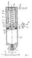
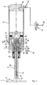
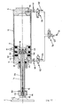
- Fig. 1 is a device for moving objects 1, such as workpieces, components or the like, reproduced, which with a on the surface 2 of the object 1 attachable, acting like a suction cup and equipped with vacuum device 3 is.
- the suction device 3 is essentially can be placed on the surface 2 of the object 1 in a fluid-tight manner and for example from a resilient material, such as an elastomeric plastic or the like, or also made of a rigid material such as metal, plastic etc., trained and points in particular in the latter case a circumferential seal on its side facing the object 1 on (not shown), with which you can with the Surface 2 of the object 1 can come into contact.
- the suction device 3 is on a cylinder cover 4 of this pressure cylinder, which is fluid-tightly closed at the end 5 set.
- the end of the pressure cylinder 5 is from a cylinder bottom 6 essentially closed in a fluid-tight manner.
- a piston rod 7 is mounted, which the Intermediate cylinder bottom 6 and against a sealing ring 8 the cylinder base 6 is sealed.
- a Cylinder piston 9 for example by means of a screw 10, detachably fixed.
- the cylinder piston 9 is by means of a sealing collar 11 arranged on the circumference essentially fluid-tight against the inner wall of the printing cylinder 5 sealed, the sealing sleeve 11 in such a way Circumferential groove 12 of the cylinder piston 9 is inserted that their Sealing lip in the direction of the suction device 3 facing away Shows the end of the cylinder space. That way the cylinder piston 9 via the piston rod 7 in the longitudinal direction of the printing cylinder 5 guided.
- the suction device 3 stands with the one facing it the cylinder piston 9 divided cylinder space via an in Cylinder cover 4 provided through hole 13 in connection, whereby it also has a through hole 14 provided screw 15 fluid-tight on the end of the through hole facing away from the pressure cylinder 5 13 of the cylinder cover 4 is fixed.
- an air filter 16 in Form a vacuum filter arranged to prevent entry Impurities such as dust particles, moisture or to avoid the like in the interior of the cylinder 5.
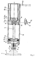
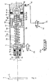
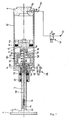
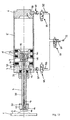
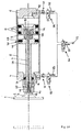
- the cylinder piston 9 is preloaded such that it with the suction device 3 corresponding cylinder space tends to enlarge to one in this cylinder space Generate negative pressure as soon as the cylinder piston 9 out its rest position shown in Fig. 1, in which he comes to rest on the cylinder base 6, in its in Fig. 2nd shown position immediately before grasping the object 2, in which it is moved in the direction of the suction device 3 has been relocated and the suction device 3 the surface 2 of the object 1 has been placed (Fig. 3).
- the piston rod 7 has on its the cylinder piston 9 opposite end a collar 17, being on the piston rod 7 a both on the Suction device 3 facing away from the cylinder base 6 as well as helical spring 18 supporting the collar 17 sits which the cylinder piston 9 elastically in the direction of the cylinder bottom 6 and consequently in the direction of the suction device 3 biased end of the pressure cylinder 5.
- the collar 17 is on the end of the piston rod 7 arranged thread by means of an adjusting screw 19 releasably fixed to the piston rod 7, so that the Waistband 17 by turning the adjusting screw 19 in the longitudinal direction the piston rod 7 displaceable and that of the coil spring 18 caused bias by compressing the same is therefore changeable.
- the transfer device shown optionally fluidically, in particular pneumatically Air pressure, or electromagnetic.
- one fluidic drive has between the cylinder piston 9 and the cylinder bottom 6 arranged cylinder space Fluid port 20, which with an actuator 21 in Form of a control valve designed as a 3/2-way valve Is provided.
- the actuator 21 is in turn with a Pressurized fluid source 22, for example a compressed air source, connected.
- the collar 17 connected to the piston rod 7 in the form of a permanent magnet 17a, which with an electromagnet 23 in the form of a line 24 interacts with a coil to which electrical current can be applied.
- the electromagnet 23 is one around the circumference Cover 25 is arranged, which on the printing cylinder 5th facing, rear end of the cylinder cover 6 releasably fixed, for example screwed.
- a damping ring 26 is arranged around the Impact of the cylinder piston 9 on the cylinder base 6 acting shock load to mitigate. Furthermore, the cylinder bottom 6 on its the suction device 3 or the pressure cylinder 5 opposite side with a central recess 26 for receiving the coil spring 18 in that shown in Fig. 2 Provide the position of the cylinder piston 9.
- the electromagnet 23 supplied with electrical current via the lines 24 and the cylinder piston 9 due to the opposite End of the piston rod 7 permanent magnets 17a inductively in the position shown in Fig. 2 postponed.
- the coil spring 18 can be dimensioned so that in connection with the suction device 3 standing cylinder space sets a negative pressure of about 0.7 bar.
- the remaining stroke of the cylinder piston 9, i.e. the difference path the same in the position shown in Fig. 3 1, can be used for maintenance of the vacuum with minor leaks between the suction device 3 and the object 1 and / or in connection with the suction device 3 standing cylinder space.
- This residual stroke should be appropriate at least 50% of the total stroke of the cylinder piston 9, i.e. of the difference path of the same in that shown in Fig. 2 Position with respect to the rest position according to FIG. 1, be.
- the position of the cylinder piston according to FIG. 2 for storage of item 2 corresponds to the position for gripping of an object and can therefore maintain it to be another item from its place of origin to move to another location.
- a fluidic Drive means that the transfer device in the event of repeated suction and removal of objects 1 only one cylinder filling for each operation of pressurized fluid required and therefore extremely can be operated inexpensively.
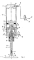
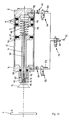
- the device shown in Fig. 4 for converting Objects 1 differ from that in FIGS. 1 to 3 device shown in particular in that the Suction device 3 on the pressure cylinder 5 facing away End of the piston rod 7 is arranged and the piston rod 7 passes through the cylinder cover 4, so that the suction device 3 telescopic in the pressure piston via the piston rod 7 5 is performed.
- the piston rod 7 is with a longitudinal through hole arranged in the longitudinal direction 28 provided, on which the printing cylinder 5 facing away End the suction device 3 with the interposition of a Air filter 16, such as a vacuum filter, via a screw 15 with one with the through bore 28 of the piston rod 7 aligned through bore 14 fluid-tight is.
- the piston rod 7 is in turn in the cylinder cover 4 stored fluid-tight using sealing rings 29.
- Piston rod 7 mounted on a guide element 30, which on its the piston rod 7 or connected to it Suction device 3 facing away from the cylinder piston 9 communicates and via the coil spring 18 is biased away from this.
- the guide element 30 is in the embodiment shown from an end of the suction device 3 facing away from the Piston rod 7 screwed sleeve 31, which has an external thread is screwed to a further sleeve 32.
- the Sleeve 32 has on its side facing away from sleeve 31 central opening 33.
- a stub shaft 34 is fixed, which through the opening 33 in the of the sleeves 31, 32 of the guide element 30 engages formed interior.
- the stub of the waves 34 is at the end with one serving as an abutment Wave collar 35 equipped, which in the in Fig. 4th shown rest position on the cylinder piston 9 facing Sleeve 32 of the guide element 30 for contact comes.
- the guide element 30 is in the direction of that in FIG. 4 shown, retracted position in the pressure cylinder 5 preloaded elastically, which by means of a on the piston rod 7 seated coil spring 37 is guaranteed which is on the one hand on the cylinder cover 4, on the other hand is supported on the sleeve 31 of the guide element 30.
- the spring constant is the guide element 31 preloading coil spring 37 chosen less than that Spring constant of the cylinder piston 9 preloading Coil spring 18.
- the guide element 30 is fluid permeable trained by being fluid permeable in the one hand Printing cylinder 5 is mounted.
- the sleeve has 31 of the guide element 30 through bores 38, which the cylinder chamber 4 facing the cylinder space with the interior of the guide element 30, in which the fixed to the cylinder piston 9 shaft stub 34 engages the opening 33, connects.
- a fluid, in particular pneumatic, drive provided.
- a fluid connection 39 equipped, on which there is a throttle check valve 40 and an actuator 41 in the form of a 3/2-way valve connect.
- the actuator 41 is again with a pressure fluid source 22, for example a compressed air source, connected.
- the side of the cylinder piston facing the suction device 3 9 arranged cylinder space has another Fluid port 42 on which there is another Actuator 43 connects, which is equipped as a 2/2-way valve is and to control or monitor the means of the cylinder piston 9 can be generated in this cylinder space Vacuum serves.
- an actuator provided with the reference symbol 43a in FIG. 4 be provided, which is designed as a 3/3-way valve and a venting / blocking or venting the with the Suction device 3 ensures corresponding cylinder space.
- the cylinder piston 9 also carries an annular permanent magnet 44, which e.g. with stationary on the outside of the pressure cylinder 5 arranged magnetic switches (not shown) for automatic control of the actuators 41, 43 depending on the position of the cylinder piston 9 cooperates.
- the mode of operation of the device is shown below 4 to 9 explained in more detail.
- the piston rod 7 is used to grip the object 1 with the suction device 3 fixed to the end face thereon initially from its rest position shown in FIG. 4 telescoped into the position shown in Fig. 5, in the it is completely pulled out of the pressure cylinder 5 and the Sleeve 31 of the guide element 30 with the cylinder cover 4 comes into contact.
- the actuator 43 from its position shown in FIG. 4 (blocking position) in the position shown in Fig. 5 (passage) and that Actuator 41 from the position shown in Fig. 4 (Passage) switched to the position shown in Fig. 5, in which the actuator 41, the fluid port 39 via the Throttle check valve 40 connects to the pressure fluid source 22.
- the coil springs 18, 37 can in turn be dimensioned in this way be that in the with the suction device 3 in Connected cylinder space a negative pressure of about 0.7 bar.
- the remaining stroke of the cylinder piston 9, i.e. the difference path of the same in that shown in Fig. 8 Position with respect to the rest position shown in FIG. 4, can Maintaining negative pressure in the event of minor leaks between the suction device 3 and the object 1 and / or in the one corresponding to the suction device 3 Serve cylinder space.
- the entire process can be automated happen by the arranged on the circumference of the impression cylinder 5 Magnetic switch (not shown) depending on the position of the cylinder piston 9 with that fixed on it Permanent magnets 44 interact and the actuators 41, 43 in the manner explained in each case toggle automatically.
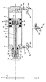
- Fig. 10 shows a compared to the transfer device according to Fig. 4 to 9 modified device, in which the the end of the piston rod facing away from the suction device 3 7 by means of a screw fixed guide element 30 a sealing collar arranged in a circumferential groove 46 47 fluid-tight against the inner wall of the printing cylinder 5 is sealed.
- a sealing collar arranged in a circumferential groove 46 47 fluid-tight against the inner wall of the printing cylinder 5 is sealed.
- a stop collar 49 is arranged, which over a damping ring 50 in the rest position shown in FIG. 10 with the outer end face of the cylinder cover 4 is in contact.
- the suction device 3 corresponds via the passage contact 14 of the screw 15, in particular Air filter 16 designed as a vacuum filter and the central through bore 28 in the piston rod 7 exclusively with the between the guide member 30 and the Cylinder piston 9 arranged cylinder space, the cylinder piston 9 as a result of the caused by the coil spring 18 Preload is preloaded so that it The aim is to enlarge the cylinder space.
- the piston rod 7 is on the cylinder cover 4 with the interposition of a Sealing rings 29 stored fluid-tight.
- the cylinder piston 9 is driven in the conversion device 10 again fluid, in particular pneumatic.
- the fluid connection 42 corresponds to this between the cylinder cover 4 and the guide element 30 arranged cylinder space.
- a throttle check valve 51 and an actuator 52 in Form of a 3/2-way valve connected, its vent connection is equipped with a fixed throttle 53.
- Fluid connections 39, 42 are with a further actuator 56 connected in the form of a 5/2-way valve.
- a throttle section 57 closes, on the other hand, a pressure fluid source 22, the actuator 56 a common control with the actuators 52, 54 equipped fluid connections 42, 39 guaranteed.
- the cylinder piston 9 in turn carries a permanent magnet 44, which is arranged stationary on the pressure cylinder 5 Magnetic switches (not shown) for automatic Control of the actuators 52, 54, 56 depending on the Position of the cylinder piston 9 cooperates.
- the piston rod 7 is used to grip the object 1 with the suction device 3 fixed to the end face thereon first from its rest position shown in FIG telescopes the position shown in Fig. 12, in the it is completely pulled out of the pressure cylinder 5.
- the actuator 52 from its shown in Fig. 10 Position in which it is on the suction device 3 facing side of the guide element 30 arranged cylinder space via the fluid connection 42, the throttle check valve 51 and the actuator 56 with the pressure fluid source 22 connects, into that shown in FIGS. 11 and 12 Position (passage to the outside via the fixed throttle 53) and the actuator 56 from its shown in Fig.
- the cylinder piston 9 is initially out of its rest position 10, in which it rests on the cylinder base 6, moved to the position shown in Fig. 11, in which it is in contact with the guide element 30 comes.
- the one corresponding to the suction device 3, between the guide element 30 and the cylinder piston 9 arranged cylinder space under compression of the Coil spring 18 downsized and finally practical fully compressed.
- a longitudinal displacement of the guide element 30 with the piston rod 7 arranged suction device 3 until this time thereby largely prevented by the fixed throttle 53 of the actuator 52 from the associated cylinder space escaping air and thus a possible shift of the guide element 30 in the direction of the cylinder cover 4 opposed to a certain counter pressure.
- the cylinder space corresponding to the suction device 3 between the guide element 30 and the cylinder piston 9 is already completely compressed, so that in particular light objects 1 during the placement of the suction device 3 not blown away from its removal position can be.
- the coil spring 18 can in turn be dimensioned approximately in this way be that the cylinder piston 9 so far from the guide element 30 displaced that in the with the suction device 3 communicating cylinder space a negative pressure of about 0.7 bar is set.
- the remaining one Residual vacuum stroke i.e. the difference in the distance between the guide element 30 and the cylinder piston 9 in the in Fig. 13 position shown and in the position according to Fig. 10, in which the coil spring 18 practically completely is expanded, serves to maintain the negative pressure during the displacement of the piston rod 7 and thus to maintain the required negative pressure in the event of minor leaks with the suction device 3 corresponding cylinder space between the guide element 30 and the cylinder piston 9.
- the cylinder space between the cylinder piston 9 and the cylinder base 6 is about the fluid port 39, the throttle check valve 40 and actuators 54, 56 are still connected to the environment, so that the cylinder piston 9 together with the guide element 30 while maintaining the negative pressure in the cylinder space arranged between them in the impression cylinder 5 is inserted. In this way it works the suction device 3 applied negative pressure and will the item 1 from its dashed line in Fig. 14 Recording position raised.
- the on the the Suction device 3 facing end of the piston rod 49 arranged Stop collar 49 comes over the damping ring 50 to the front of the cylinder cover 4 to the system.
- the actuator 56 is shown in Fig. 14 shown position, in which it is between the cylinder cover 4 and the guide element 30 arranged cylinder space connects to the pressure fluid source 22, in its 15 shown position switched, in which it the pressure fluid source 22 via the actuator 54 with the Cylinder space between the cylinder base 6 and the cylinder piston 9 on its side facing away from the suction device 3 combines.
- the actuators 52, 56 connected to the fluid connection 42 switched to passage, so that there is ambient pressure.
- the cylinder piston 7 is located with the suction device 3 shown in FIG. 15, pulled out of the printing cylinder 5 position again in the position in which the object is placed becomes.
- the placement process is ensured in this position by that the cylinder piston 9 under constant Overpressure in the between the cylinder piston 9 and the cylinder bottom 6 arranged cylinder space against that of the coil spring 18 caused preload further in Direction of the cylinder cover 4 is shifted so that it comes into contact with the guide element 30 (cf. FIG. 12).
- This is the between the guide member 30 and the cylinder piston 9 arranged, corresponding to the suction device 3 Cylinder chamber practically completely compressed, so that no vacuum on the suction device 3 more and the object 1 from the suction device 3 is solved.
- the actuator 56 For pushing the piston rod 7 into the pressure cylinder 5 is then the actuator 56 from its position Fig. 15 switched to the position shown in Fig. 16, in which it is between the cylinder cover 4 and the guide element 30 arranged cylinder space over the fluid connection 42 and the actuators 52, 56 with the pressure fluid source 22 connects.
- the actuator 54 of its position shown in Fig. 15 in the in Fig. 16 shown position switched, in which it the between the cylinder piston 9 and the cylinder base 6 arranged Cylinder space via the fluid connection 39 and the fixed throttle 55 of the actuator 54 connects to the environment.
- the actuator 54 can again from the position shown in Fig. 16 to its rest position (see e.g. Fig. 10), so that the Fixed throttle 55 of the actuator 56 is bridged. Thereby acts on the side of the Cylinder piston 9 practically no more back pressure and Coil spring 18 urges the guide member 30 and the cylinder piston 9 apart. In this way the insertion process the piston rod 7 in the pressure cylinder 9 facilitated.
- the entire process can in turn be automated Done by the way the scope of the Printing cylinder 5 arranged magnetic switch (not shown) depending on the position of the cylinder piston 9 with the permanent magnet 44 attached to it Interact and the actuators 52, 54, 56 in automatically switch in the manner explained.
- the device shown in FIGS. 10 to 16 faces 4 to 9 in particular the advantage on that the displacement of the piston rod 7 with the suction device 3 completely independent of the generation of a happens at the suction device 3 negative pressure and the piston rod 7 while maintaining one at the Suction device 3 applied vacuum can be telescoped as desired is.
Landscapes
- Engineering & Computer Science (AREA)
- Mechanical Engineering (AREA)
- Manipulator (AREA)
- Sheets, Magazines, And Separation Thereof (AREA)
Applications Claiming Priority (2)
| Application Number | Priority Date | Filing Date | Title |
|---|---|---|---|
| DE2003121874 DE10321874A1 (de) | 2003-05-15 | 2003-05-15 | Vorrichtung zum Umsetzen von Gegenständen |
| DE10321874 | 2003-05-15 |
Publications (2)
| Publication Number | Publication Date |
|---|---|
| EP1477439A1 true EP1477439A1 (fr) | 2004-11-17 |
| EP1477439B1 EP1477439B1 (fr) | 2006-12-20 |
Family
ID=33016408
Family Applications (1)
| Application Number | Title | Priority Date | Filing Date |
|---|---|---|---|
| EP20040011489 Expired - Lifetime EP1477439B1 (fr) | 2003-05-15 | 2004-05-14 | Dispositif pour transférer des objets |
Country Status (2)
| Country | Link |
|---|---|
| EP (1) | EP1477439B1 (fr) |
| DE (2) | DE10321874A1 (fr) |
Cited By (15)
| Publication number | Priority date | Publication date | Assignee | Title |
|---|---|---|---|---|
| WO2005105628A1 (fr) * | 2004-04-13 | 2005-11-10 | Festo Ag & Co | Dispositif d'aspiration et dispositif de manipulation equipe d'un tel dispositif |
| AT502563B1 (de) * | 2005-10-12 | 2007-06-15 | Trumpf Maschinen Austria Gmbh | Greiferkopf mit vakuumgreifer und steuerventil dazu sowie ein verfahren zum betrieb eines solchen |
| US7762382B2 (en) | 2006-01-09 | 2010-07-27 | Scanvaegt International A/S | Method and a system for transferring of items |
| DE102011083498A1 (de) * | 2011-09-27 | 2013-03-28 | Uwe Reifenhäuser | Sauggreifer und Verfahren zum Reinigen eines Sauggreifers |
| CN106865229A (zh) * | 2017-03-14 | 2017-06-20 | 京东方科技集团股份有限公司 | 吸附装置 |
| CN108563019A (zh) * | 2018-03-04 | 2018-09-21 | 铁清木 | 一种智能vr眼镜 |
| EP3483097A3 (fr) * | 2017-10-23 | 2019-07-31 | TRUMPF Werkzeugmaschinen GmbH + Co. KG | Dispositif de retenue de pièce ainsi que dispositif de manipulation de pièce et agencement d'usinage des pièces mécaniques doté d'un dispositif de retenue |
| CN110902381A (zh) * | 2019-12-10 | 2020-03-24 | 江西富益特显示技术有限公司 | 多工位偏光片自动取放料装置 |
| CN111392405A (zh) * | 2020-03-23 | 2020-07-10 | 广州市妙伊莲科技有限公司 | 一种用于智慧生产线的可靠性高的夹取系统 |
| CN112278851A (zh) * | 2020-09-24 | 2021-01-29 | 彩虹集团有限公司 | 一种液晶平板玻璃的下板展板吸盘架 |
| CN113104645A (zh) * | 2021-02-26 | 2021-07-13 | 广州晶绘实业有限公司 | 具有缓冲的大吸力真空吸盘及输送装置 |
| CN113524108A (zh) * | 2021-07-14 | 2021-10-22 | 贵州电网有限责任公司 | 一种标示牌杆式伸缩安装工具 |
| CN115893000A (zh) * | 2022-12-29 | 2023-04-04 | 中建八局第四建设有限公司 | 一种免弯腰快速拾取铁质零件的装置 |
| CN117184886A (zh) * | 2022-06-01 | 2023-12-08 | Smc(中国)有限公司 | 自吸搬运装置 |
| CN117783826A (zh) * | 2023-12-28 | 2024-03-29 | 无锡芯启博电子有限公司 | 一种芯片ft测试装置 |
Families Citing this family (6)
| Publication number | Priority date | Publication date | Assignee | Title |
|---|---|---|---|---|
| DE102008021029A1 (de) * | 2008-04-25 | 2009-07-23 | De-Sta-Co Europe Gmbh | Greifvorrichtung |
| CN104210845B (zh) * | 2014-09-19 | 2016-03-23 | 济南大学 | 一种具有复合运动的搬运装置 |
| CN109527003A (zh) * | 2018-12-05 | 2019-03-29 | 安徽侬安康食品有限公司 | 一种烘烤饼干气动吸头 |
| DE102019219745A1 (de) * | 2019-12-16 | 2021-06-17 | Volkswagen Aktiengesellschaft | Unterdruckgreifer |
| DE102022201573B3 (de) | 2022-02-16 | 2023-02-02 | Volkswagen Aktiengesellschaft | Unterdruckgreifer |
| CN115465662B (zh) * | 2022-09-20 | 2023-11-03 | 中建安装集团有限公司 | 一种地铁轨排拼装用扣件物料一体化取放操作末端 |
Citations (2)
| Publication number | Priority date | Publication date | Assignee | Title |
|---|---|---|---|---|
| DE900562C (de) * | 1943-07-04 | 1953-12-28 | Sachsenwerk Licht & Kraft Ag | Saugheber fuer Blechscheiben, Papier od. dgl. |
| US3033604A (en) * | 1959-02-18 | 1962-05-08 | Winkler Sallert & Co Ag Maschf | Lifting and transporting device for holding hollow articles |
Family Cites Families (6)
| Publication number | Priority date | Publication date | Assignee | Title |
|---|---|---|---|---|
| US3628654A (en) * | 1969-10-01 | 1971-12-21 | Edward F Haracz | Vacuum belt conveyors |
| US3902605A (en) * | 1972-11-09 | 1975-09-02 | Hambro Forest Products Inc | Suction lifting apparatus |
| DE2549514C3 (de) * | 1975-11-05 | 1978-10-26 | 4P Verpackungen Gmbh, 8960 Kempten | Übergabeförderer mit Saugköpfen zur Aufnahme und Halterung von vorzugsweise becherförmigen Gegenständen |
| US4029351A (en) * | 1976-06-02 | 1977-06-14 | International Business Machines Corporation | Bernoulli pickup head with self-restoring anti-tilt improvement |
| US4266905A (en) * | 1979-04-20 | 1981-05-12 | Board Of Regents For Education Of The State Of Rhode Island | Apparatus for acquiring workpieces from a storage bin or the like |
| SE446621B (sv) * | 1980-02-04 | 1986-09-29 | Sten Andersson | Vakuumlyftanordning for gods eller andra foremal |
-
2003
- 2003-05-15 DE DE2003121874 patent/DE10321874A1/de not_active Withdrawn
-
2004
- 2004-05-14 EP EP20040011489 patent/EP1477439B1/fr not_active Expired - Lifetime
- 2004-05-14 DE DE200450002349 patent/DE502004002349D1/de not_active Expired - Fee Related
Patent Citations (2)
| Publication number | Priority date | Publication date | Assignee | Title |
|---|---|---|---|---|
| DE900562C (de) * | 1943-07-04 | 1953-12-28 | Sachsenwerk Licht & Kraft Ag | Saugheber fuer Blechscheiben, Papier od. dgl. |
| US3033604A (en) * | 1959-02-18 | 1962-05-08 | Winkler Sallert & Co Ag Maschf | Lifting and transporting device for holding hollow articles |
Cited By (19)
| Publication number | Priority date | Publication date | Assignee | Title |
|---|---|---|---|---|
| WO2005105628A1 (fr) * | 2004-04-13 | 2005-11-10 | Festo Ag & Co | Dispositif d'aspiration et dispositif de manipulation equipe d'un tel dispositif |
| AT502563B1 (de) * | 2005-10-12 | 2007-06-15 | Trumpf Maschinen Austria Gmbh | Greiferkopf mit vakuumgreifer und steuerventil dazu sowie ein verfahren zum betrieb eines solchen |
| US7762382B2 (en) | 2006-01-09 | 2010-07-27 | Scanvaegt International A/S | Method and a system for transferring of items |
| DE102011083498A1 (de) * | 2011-09-27 | 2013-03-28 | Uwe Reifenhäuser | Sauggreifer und Verfahren zum Reinigen eines Sauggreifers |
| EP2574576A1 (fr) | 2011-09-27 | 2013-04-03 | Uwe Reifenhäuser | Pince aspirante et procédé destiné au nettoyage d'une pince aspirante |
| DE102011083498B4 (de) | 2011-09-27 | 2014-08-21 | Uwe Reifenhäuser | Sauggreifer und Verfahren zum Reinigen eines Sauggreifers |
| CN106865229A (zh) * | 2017-03-14 | 2017-06-20 | 京东方科技集团股份有限公司 | 吸附装置 |
| CN106865229B (zh) * | 2017-03-14 | 2019-11-01 | 京东方科技集团股份有限公司 | 吸附装置 |
| EP3483097A3 (fr) * | 2017-10-23 | 2019-07-31 | TRUMPF Werkzeugmaschinen GmbH + Co. KG | Dispositif de retenue de pièce ainsi que dispositif de manipulation de pièce et agencement d'usinage des pièces mécaniques doté d'un dispositif de retenue |
| CN108563019A (zh) * | 2018-03-04 | 2018-09-21 | 铁清木 | 一种智能vr眼镜 |
| CN108563019B (zh) * | 2018-03-04 | 2023-09-26 | 铁清木 | 一种智能vr眼镜 |
| CN110902381A (zh) * | 2019-12-10 | 2020-03-24 | 江西富益特显示技术有限公司 | 多工位偏光片自动取放料装置 |
| CN111392405A (zh) * | 2020-03-23 | 2020-07-10 | 广州市妙伊莲科技有限公司 | 一种用于智慧生产线的可靠性高的夹取系统 |
| CN112278851A (zh) * | 2020-09-24 | 2021-01-29 | 彩虹集团有限公司 | 一种液晶平板玻璃的下板展板吸盘架 |
| CN113104645A (zh) * | 2021-02-26 | 2021-07-13 | 广州晶绘实业有限公司 | 具有缓冲的大吸力真空吸盘及输送装置 |
| CN113524108A (zh) * | 2021-07-14 | 2021-10-22 | 贵州电网有限责任公司 | 一种标示牌杆式伸缩安装工具 |
| CN117184886A (zh) * | 2022-06-01 | 2023-12-08 | Smc(中国)有限公司 | 自吸搬运装置 |
| CN115893000A (zh) * | 2022-12-29 | 2023-04-04 | 中建八局第四建设有限公司 | 一种免弯腰快速拾取铁质零件的装置 |
| CN117783826A (zh) * | 2023-12-28 | 2024-03-29 | 无锡芯启博电子有限公司 | 一种芯片ft测试装置 |
Also Published As
| Publication number | Publication date |
|---|---|
| DE10321874A1 (de) | 2004-12-02 |
| EP1477439B1 (fr) | 2006-12-20 |
| DE502004002349D1 (de) | 2007-02-01 |
Similar Documents
| Publication | Publication Date | Title |
|---|---|---|
| EP1477439B1 (fr) | Dispositif pour transférer des objets | |
| EP1777177B1 (fr) | Butée avec amortisseur | |
| EP2722165B1 (fr) | Circuit hydraulique pour un axe hydraulique et axe hydraulique | |
| DE102008045426B4 (de) | Antriebsvorrichtung mit einem durch Fluidkraft betätigbaren Doppelhubzylinder | |
| EP1484142A1 (fr) | Appareil de levage par aspiration muni d'un système cylindre- piston pour produire une dépression | |
| EP2637852A1 (fr) | Essieu hydraulique | |
| EP3394454A1 (fr) | Soupape, en particulier distributeur à tiroir à 4/2 voies | |
| DE102017124472B3 (de) | Vakuumsaugnapf mit aktiv variierbarer Länge | |
| DE102013224657A1 (de) | Hydraulische Anordnung | |
| EP2019075B1 (fr) | Dispositif destiné au serrage et/ou au maintien de pièces à usiner | |
| DE102014004688A1 (de) | Sauggreifvorrichtung und Verfahren zum Betreiben einer Sauggreifvorrichtung | |
| EP0433586B1 (fr) | Système d'aspiration pour organes de soudage refroidis par un élément | |
| DE202004019495U1 (de) | Durch Druckmitteldruck, insbesondere pneuamtisch, betätigte Kolben-Zylinder-Einheit, bei welcher ein mit einer Kolbenstange verbundener Kolben durch Druckmittelbeaufschlagung linear bewegbar ist, z.B. druckmittelbetätigbare Kniehebelspannvorrichtung, insbesondere für den Karosseriebau der Kfz-Industrie | |
| DE10361619B4 (de) | Hydraulische Betätigungsvorrichtung | |
| DE102023109048A1 (de) | Sauggreifer, Greifmodul mit einer Mehrzahl von Sauggreifern sowie Sauggreifvorrichtung mit einer Mehrzahl von Greifmodulen | |
| EP1719720B1 (fr) | Dispositif de contrôle pour une ventouse de préhension | |
| DE3803009C2 (de) | Hydraulischer Antrieb | |
| DE102006003660B4 (de) | Einrichtung zur Sicherung der Bewegungsreihenfolge von mindestens zwei fluidbetätigten Verdrängereinheiten | |
| DE102018003211B4 (de) | Kolben-Zylinder-Einrichtung mit automatischer Abschaltung, Vakuum-Halter und Vakuum-Auflagetisch | |
| DE102006004295A1 (de) | Magnetgreifsystem | |
| WO2018086778A1 (fr) | Procédé pour faire fonctionner un élément de réglage pneumatique et élément de réglage | |
| DE102006051340B4 (de) | Vorrichtung zur Durchführung von Stellvorgängen an einer rotierbar gelagerten Trommel einer Druckmaschine | |
| DE10211724B4 (de) | Medienkupplungssystem und Verfahren zu seiner Ankupplung | |
| DE19912378A1 (de) | Hubsaugeinrichtung | |
| EP4644062A1 (fr) | Dispositif de préhension avec unité de poussée |
Legal Events
| Date | Code | Title | Description |
|---|---|---|---|
| PUAI | Public reference made under article 153(3) epc to a published international application that has entered the european phase |
Free format text: ORIGINAL CODE: 0009012 |
|
| AK | Designated contracting states |
Kind code of ref document: A1 Designated state(s): AT BE BG CH CY CZ DE DK EE ES FI FR GB GR HU IE IT LI LU MC NL PL PT RO SE SI SK TR |
|
| AX | Request for extension of the european patent |
Extension state: AL HR LT LV MK |
|
| RIN1 | Information on inventor provided before grant (corrected) |
Inventor name: IHRIG, HELMUT |
|
| 17P | Request for examination filed |
Effective date: 20050407 |
|
| AKX | Designation fees paid |
Designated state(s): DE FR GB IT |
|
| 17Q | First examination report despatched |
Effective date: 20050622 |
|
| GRAP | Despatch of communication of intention to grant a patent |
Free format text: ORIGINAL CODE: EPIDOSNIGR1 |
|
| GRAS | Grant fee paid |
Free format text: ORIGINAL CODE: EPIDOSNIGR3 |
|
| GRAA | (expected) grant |
Free format text: ORIGINAL CODE: 0009210 |
|
| AK | Designated contracting states |
Kind code of ref document: B1 Designated state(s): DE FR GB IT |
|
| REG | Reference to a national code |
Ref country code: GB Ref legal event code: FG4D Free format text: NOT ENGLISH |
|
| GBT | Gb: translation of ep patent filed (gb section 77(6)(a)/1977) |
Effective date: 20061220 |
|
| REF | Corresponds to: |
Ref document number: 502004002349 Country of ref document: DE Date of ref document: 20070201 Kind code of ref document: P |
|
| ET | Fr: translation filed | ||
| PLBE | No opposition filed within time limit |
Free format text: ORIGINAL CODE: 0009261 |
|
| STAA | Information on the status of an ep patent application or granted ep patent |
Free format text: STATUS: NO OPPOSITION FILED WITHIN TIME LIMIT |
|
| 26N | No opposition filed |
Effective date: 20070921 |
|
| PGFP | Annual fee paid to national office [announced via postgrant information from national office to epo] |
Ref country code: DE Payment date: 20080531 Year of fee payment: 5 |
|
| PGFP | Annual fee paid to national office [announced via postgrant information from national office to epo] |
Ref country code: IT Payment date: 20080522 Year of fee payment: 5 |
|
| PGFP | Annual fee paid to national office [announced via postgrant information from national office to epo] |
Ref country code: GB Payment date: 20080409 Year of fee payment: 5 |
|
| PGFP | Annual fee paid to national office [announced via postgrant information from national office to epo] |
Ref country code: FR Payment date: 20090519 Year of fee payment: 6 |
|
| GBPC | Gb: european patent ceased through non-payment of renewal fee |
Effective date: 20090514 |
|
| PG25 | Lapsed in a contracting state [announced via postgrant information from national office to epo] |
Ref country code: GB Free format text: LAPSE BECAUSE OF NON-PAYMENT OF DUE FEES Effective date: 20090514 |
|
| PG25 | Lapsed in a contracting state [announced via postgrant information from national office to epo] |
Ref country code: DE Free format text: LAPSE BECAUSE OF NON-PAYMENT OF DUE FEES Effective date: 20091201 |
|
| REG | Reference to a national code |
Ref country code: FR Ref legal event code: ST Effective date: 20110131 |
|
| PG25 | Lapsed in a contracting state [announced via postgrant information from national office to epo] |
Ref country code: IT Free format text: LAPSE BECAUSE OF NON-PAYMENT OF DUE FEES Effective date: 20090514 |
|
| PG25 | Lapsed in a contracting state [announced via postgrant information from national office to epo] |
Ref country code: FR Free format text: LAPSE BECAUSE OF NON-PAYMENT OF DUE FEES Effective date: 20100531 |