EP2574576A1 - Pince aspirante et procédé destiné au nettoyage d'une pince aspirante - Google Patents
Pince aspirante et procédé destiné au nettoyage d'une pince aspirante Download PDFInfo
- Publication number
- EP2574576A1 EP2574576A1 EP12177978A EP12177978A EP2574576A1 EP 2574576 A1 EP2574576 A1 EP 2574576A1 EP 12177978 A EP12177978 A EP 12177978A EP 12177978 A EP12177978 A EP 12177978A EP 2574576 A1 EP2574576 A1 EP 2574576A1
- Authority
- EP
- European Patent Office
- Prior art keywords
- vacuum cylinder
- gripping element
- drive
- piston
- gripping
- Prior art date
- Legal status (The legal status is an assumption and is not a legal conclusion. Google has not performed a legal analysis and makes no representation as to the accuracy of the status listed.)
- Withdrawn
Links
- 238000004140 cleaning Methods 0.000 title claims abstract description 23
- 238000000034 method Methods 0.000 title claims abstract description 13
- 235000013305 food Nutrition 0.000 claims description 20
- 238000005520 cutting process Methods 0.000 claims description 16
- 238000006073 displacement reaction Methods 0.000 claims description 5
- 238000011109 contamination Methods 0.000 description 2
- 239000010794 food waste Substances 0.000 description 2
- 241000894006 Bacteria Species 0.000 description 1
- 241000233866 Fungi Species 0.000 description 1
- 235000014676 Phragmites communis Nutrition 0.000 description 1
- 238000000151 deposition Methods 0.000 description 1
- 238000004519 manufacturing process Methods 0.000 description 1
- 244000005700 microbiome Species 0.000 description 1
- 238000004806 packaging method and process Methods 0.000 description 1
- 230000002028 premature Effects 0.000 description 1
- 239000000523 sample Substances 0.000 description 1
- 238000007789 sealing Methods 0.000 description 1
- 238000009423 ventilation Methods 0.000 description 1
Images


Classifications
-
- B—PERFORMING OPERATIONS; TRANSPORTING
- B65—CONVEYING; PACKING; STORING; HANDLING THIN OR FILAMENTARY MATERIAL
- B65G—TRANSPORT OR STORAGE DEVICES, e.g. CONVEYORS FOR LOADING OR TIPPING, SHOP CONVEYOR SYSTEMS OR PNEUMATIC TUBE CONVEYORS
- B65G47/00—Article or material-handling devices associated with conveyors; Methods employing such devices
- B65G47/74—Feeding, transfer, or discharging devices of particular kinds or types
- B65G47/90—Devices for picking-up and depositing articles or materials
- B65G47/91—Devices for picking-up and depositing articles or materials incorporating pneumatic, e.g. suction, grippers
- B65G47/917—Devices for picking-up and depositing articles or materials incorporating pneumatic, e.g. suction, grippers control arrangements
-
- A—HUMAN NECESSITIES
- A22—BUTCHERING; MEAT TREATMENT; PROCESSING POULTRY OR FISH
- A22C—PROCESSING MEAT, POULTRY, OR FISH
- A22C17/00—Other devices for processing meat or bones
- A22C17/02—Apparatus for holding meat or bones while cutting
-
- B—PERFORMING OPERATIONS; TRANSPORTING
- B25—HAND TOOLS; PORTABLE POWER-DRIVEN TOOLS; MANIPULATORS
- B25J—MANIPULATORS; CHAMBERS PROVIDED WITH MANIPULATION DEVICES
- B25J11/00—Manipulators not otherwise provided for
- B25J11/0045—Manipulators used in the food industry
-
- B—PERFORMING OPERATIONS; TRANSPORTING
- B25—HAND TOOLS; PORTABLE POWER-DRIVEN TOOLS; MANIPULATORS
- B25J—MANIPULATORS; CHAMBERS PROVIDED WITH MANIPULATION DEVICES
- B25J15/00—Gripping heads and other end effectors
- B25J15/06—Gripping heads and other end effectors with vacuum or magnetic holding means
- B25J15/0616—Gripping heads and other end effectors with vacuum or magnetic holding means with vacuum
-
- B—PERFORMING OPERATIONS; TRANSPORTING
- B25—HAND TOOLS; PORTABLE POWER-DRIVEN TOOLS; MANIPULATORS
- B25J—MANIPULATORS; CHAMBERS PROVIDED WITH MANIPULATION DEVICES
- B25J19/00—Accessories fitted to manipulators, e.g. for monitoring, for viewing; Safety devices combined with or specially adapted for use in connection with manipulators
- B25J19/0058—Means for cleaning manipulators, e.g. dust removing means
-
- B—PERFORMING OPERATIONS; TRANSPORTING
- B26—HAND CUTTING TOOLS; CUTTING; SEVERING
- B26D—CUTTING; DETAILS COMMON TO MACHINES FOR PERFORATING, PUNCHING, CUTTING-OUT, STAMPING-OUT OR SEVERING
- B26D7/00—Details of apparatus for cutting, cutting-out, stamping-out, punching, perforating, or severing by means other than cutting
- B26D7/01—Means for holding or positioning work
- B26D2007/011—Means for holding or positioning work by clamping claws, e.g. in high speed slicers for food products
-
- B—PERFORMING OPERATIONS; TRANSPORTING
- B26—HAND CUTTING TOOLS; CUTTING; SEVERING
- B26D—CUTTING; DETAILS COMMON TO MACHINES FOR PERFORATING, PUNCHING, CUTTING-OUT, STAMPING-OUT OR SEVERING
- B26D2210/00—Machines or methods used for cutting special materials
- B26D2210/02—Machines or methods used for cutting special materials for cutting food products, e.g. food slicers
-
- B—PERFORMING OPERATIONS; TRANSPORTING
- B26—HAND CUTTING TOOLS; CUTTING; SEVERING
- B26D—CUTTING; DETAILS COMMON TO MACHINES FOR PERFORATING, PUNCHING, CUTTING-OUT, STAMPING-OUT OR SEVERING
- B26D7/00—Details of apparatus for cutting, cutting-out, stamping-out, punching, perforating, or severing by means other than cutting
- B26D7/08—Means for treating work or cutting member to facilitate cutting
- B26D7/088—Means for treating work or cutting member to facilitate cutting by cleaning or lubricating
-
- B—PERFORMING OPERATIONS; TRANSPORTING
- B65—CONVEYING; PACKING; STORING; HANDLING THIN OR FILAMENTARY MATERIAL
- B65G—TRANSPORT OR STORAGE DEVICES, e.g. CONVEYORS FOR LOADING OR TIPPING, SHOP CONVEYOR SYSTEMS OR PNEUMATIC TUBE CONVEYORS
- B65G2201/00—Indexing codes relating to handling devices, e.g. conveyors, characterised by the type of product or load being conveyed or handled
- B65G2201/02—Articles
- B65G2201/0202—Agricultural and processed food products
Definitions
- the invention relates to a suction gripper and a food for food with a gripping element, a connected to the gripping element vacuum cylinder and a piston, and with a attached to the vacuum cylinder drive for the piston for moving the piston in the vacuum cylinder, wherein during operation of the suction pad a displacement of the Piston in an axial direction of the vacuum cylinder in the vacuum cylinder and in the gripping element builds a vacuum for gripping the food.
- the invention further relates to a method for cleaning such a suction pad.
- Such a suction pad is off DE 10 2008 011 980 B3 discloses:
- the known vacuum gripper has a piston-cylinder unit as a drive for moving the piston.
- a negative pressure is built up in the vacuum cylinder and in the connected gripping element.
- the piston in the vacuum cylinder defines an area of negative pressure in the gripping element and thus effectively avoids contamination of the drive with residues of the food adhered to the gripping element.
- another suction gripper of the aforementioned type EP 1 4774 39 A is another suction gripper of the aforementioned type EP 1 4774 39 A .
- the invention is based, as simple as possible to clean such a suction pad the task.
- the suction gripper Starting from the known suction gripper is proposed according to the invention to provide a quick release, which connects the vacuum cylinder to the drive, wherein after releasing the quick release of the vacuum cylinder from the drive manually, So it is removable without tools with your hands.
- the vacuum cylinder removed from the drive is easier to handle and clean.
- the piston can be removed for cleaning the interior of the vacuum cylinder either manually from the vacuum cylinder or - if it is firmly connected to the drive - remain at this.
- the quick-release closure of a suction gripper according to the invention is preferably a bayonet closure.
- other thread-like elements for example, a fastening thread - to drive and vacuum cylinder form a quick release.
- thread-like elements require a higher manufacturing accuracy, but avoid more moving parts for the quick release and thus facilitate the cleaning of the suction pad according to the invention.
- the gripping element is fixedly attached to the vacuum cylinder on a suction gripper according to the invention and has a cutting ring, which cuts into the surface of the food during gripping and thus seals the gripping element.
- a suction gripper according to the invention has a cutting ring, which cuts into the surface of the food during gripping and thus seals the gripping element.
- the out DE 10 2008 011 980 B3 known suction pads has such a gripping element.
- Such a suction gripper according to the invention is particularly suitable for fixing or exact guiding a Gutsstrangs when cutting.
- such a suction gripper has an ejector movably mounted in the vacuum cylinder in the axial direction, which exerts pressure on the surface of the food for ejecting the food through the gripping element.
- an ejector simplifies the automatic release of the suction pad from the food.
- an inventive suction gripper with attached to the vacuum cylinder gripping element advantageously a button, which is guided by the drive through the gripping element and at the beginning of a gripping operation the Drive in operation when it comes into contact with the surface of the food.
- a probe avoids the premature displacement of the piston in the vacuum cylinder when gripping, in particular, irregularly shaped foods with a suction gripper according to the invention.
- An inventive suction gripper with attached to the vacuum cylinder gripping element further preferably has a further quick release, which connects the gripping element with the vacuum cylinder, wherein after releasing the other quick release, the gripper element is manually removable from the vacuum cylinder.
- a suction gripper according to the invention can have a hose through which the vacuum cylinder is connected to the gripping element, wherein the gripping element has a flexible contact element which adapts to the surface contour when gripping the food and thus seals the gripping element.
- a suction gripper according to the invention is particularly suitable for gripping, relocating and depositing individual pieces or slices of a portioned foodstuff for the packaging.
- the vacuum cylinder is released by releasing a quick release of the drive and manually, so removed without tools with his hands, and that the vacuum cylinder cleaned separately from the drive and after cleaning on put the drive back on and the quick release is closed.
- the inventive method requires a suction pad according to the invention and is characterized by the advantages described for this.
- the vacuum cylinder is preferably parked substantially vertically in the axial direction after removal from the drive on a transport device.
- the parking on a transport device facilitates the given case automated transport of several vacuum cylinders for example, to a cleaning device, through such a cleaning device and back to the drives.
- the vertical parking with the gripping element down avoids distributing possibly adhering to the gripping element food residues in the direction of the longitudinal axis in or on the vacuum cylinder.
- a gripping element with a cutting ring such a gripping element and an ejector or a connection element with a hose through which the vacuum cylinder is connected to the gripping element, manually removed.
- the disassembly of the vacuum cylinder into its further components facilitates the cleaning in particular of the contact points between these components.
- a plurality of vacuum cylinders are collected and cleaned together in a cleaning process.
- the cleaning is more economical overall.
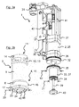
- Suction gripper 1 has a drive 2, a vacuum cylinder 3 and a gripping element 4.
- the vacuum cylinder 3 is with a Quick release 5 attached to the drive 2 and the gripping element 4 is connected to a further quick release 6 with the vacuum cylinder 3.
- Both quick-release closures are designed as "bayonet locks": To open the quick-release closures, the vacuum cylinder 3 can be pivoted counter to the drive 2, respectively the gripping element 4 with respect to the vacuum cylinder 3 after overcoming each catch 7 by about 15 ° counterclockwise. Subsequently, the vacuum cylinder 3 can be removed from the drive 2, respectively the gripping element 4 of the vacuum cylinder 3 along the longitudinal axis 8 of the suction gripper 1 according to the invention.
- the vacuum cylinder 3 has a cylindrical housing 9 with an inner diameter 10 of 63 mm and the slightly flared upper end 11 of the housing 9 on the circumference 12 each offset by 120 ° to each other three circumferentially almost completely opening openings 13 and three hook-shaped slots 14 , At the lower end 15 of the housing 9, three radially projecting pins 16 are mounted on the circumference 12 of the vacuum cylinder 3 each offset by 120 °.
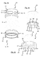
- the gripping element 4 has an outer rim 17 and one with the rim 17 by radial webs 18 (only in Fig. 1b shown) connected to cylinder 19.
- the ring 17 has an outer diameter 20 of 85 mm and the inner cylinder 19 has an inner diameter 21 of 48 mm.
- On the circumference of the ring 17 three hook-shaped slots 22 are each mounted offset by 120 °, which cooperate with the pins 16 on the vacuum cylinder 3 as a "bayonet lock".
- An outer cutting ring 23 is attached to the rim 17 and a slightly protruding inner cutting ring 24 is attached to the cylinder 19.
- the drive 2 has a cylindrical housing 25 with two end caps 26, 27, and a piston 28 guided in the housing 25 along the longitudinal axis 8.
- the piston 28 is connected to a guided through the lower end cap 26 hollow shaft 29.
- the piston 28 is connected via two attached to the end caps 26, 27 connecting cylinder 30, which lead via not shown pneumatic tubing through a Schlauch mitfiihrung 31 to a machine interface, also not shown, with compressed air.
- At the lower end cap 26 are over the Perimeter of the housing 25 each offset by 120 ° against each other three radially projecting pins 32 mounted, which cooperate with the slots 14 on the vacuum cylinder 3 as a "bayonet lock".
- the led out of the drive 2 hollow shaft 29 terminates in a further piston 33 which is provided as a double piston with two concentric, stepped staggered end faces 34, 35.
- the inner end face 34 encloses an inner suction chamber 36 with the cylinder 19 of the gripping element 4, and the outer end face 35 with a lateral surface 37 of the piston 33 and the vacuum cylinder 3 surrounds an outer suction chamber 38 of the suction gripper 1 according to the invention.
- a plunger 39 is guided, which ends in the mounted state in the gripping element 4 in a button 40.
- the button 40 closes there substantially with the inner cutting ring 24 and is guided by this.
- the plunger 39 terminates at a spring-loaded switching tongue 41, which actuates the pressure ventilation of the drive 2 for retraction of the piston 33 when actuated via a valve 42.
- the valve 42 has three connecting cylinders 43, which in turn lead via pneumatic hoses, not shown, through the hose passage 31 to the machine interface.
- an ejector 44 is loosely inserted in the assembled state.
- the ejector 44 fills this gap completely completely with completely extended from the drive 2 hollow cylinder.
- eight pins 45 are mounted, which penetrate between the webs 18 and terminate in this state with the outer cutting ring 23 is substantially flush.
- the vacuum cylinder 3 is first manually, so grabbed with the hands and slightly pressed in the direction of the longitudinal axis 8 against the drive 2 to release the pins 32 from the detents 7, then the vacuum cylinder 3 against the Drive 2 pivoted counterclockwise about the longitudinal axis 8 to release the quick release 5.
- the gripping element 4 and the ejector 44 are then withdrawn in the direction of the longitudinal axis 8 of the drive 2 and placed on a transport pallet substantially vertically, collected with further vacuum cylinders of the same cutting machine and other vacuum cylinders other cutting machines and brought to a cleaning station.
- the transport pallet, the other vacuum cylinders, the cutting machines and the cleaning station are not shown in the drawing figures.
- the vacuum cylinder 3 is again pressed manually in the direction of the longitudinal axis 8 slightly against the gripping element 4 and pivoted relative to the gripping element 4 in a counterclockwise direction about the longitudinal axis 8 in order to release the further rapid closure 6. Subsequently, the vacuum cylinder 3 and the ejector 44 are successively withdrawn in the direction of the longitudinal axis 8 of the gripping element 4. Now vacuum cylinder 3, gripping element 4 and ejector 44 are cleaned in a cleaning device, again not shown.
- the piston 33, the plunger 39 and the button 40 remain on the drive 2 and are cleaned and disinfected manually there in the meantime.
- the ejector 44 is manually set in the direction of the longitudinal axis 8 back to the gripping element 4 in the reverse direction, that the pins 45 penetrate between the webs 18 of the gripping element 4.
- the vacuum cylinder 3 is set in the direction of the longitudinal axis 8 on the gripping member 4 that the pins 16 of the vacuum cylinder 3 are in the slots 22 of the gripping member 4, pivoted clockwise about the longitudinal axis 8 and slightly in the direction of the longitudinal axis 8 against the Gripping element 4 is pressed until the further quick-release 6 engages.
- the vacuum cylinder 3 in assembly with gripping element 4 and ejector 44 is collected together with the other vacuum cylinders on the transport pallet, back to the cutting machines and mounted there.
- the vacuum cylinder 3 is set in the direction of the longitudinal axis 8 back to the drive 2, that on the one hand, the piston 33 with its inner end face 34, the inner suction chamber 36 in the cylinder 19 of the gripping member 4 and with its outer end face 35, the outer suction chamber 38 in Vacuum cylinder 3 and the button 40, the opening in the inner cutting ring 24 closes and on the other hand, the pins 32 of the drive 2 are in the slots 14 of the vacuum cylinder 3.
- the vacuum cylinder 3 is pivoted clockwise about the longitudinal axis 8 and slightly pressed in the direction of the longitudinal axis 8 against the drive 2 until the quick release 5 snaps into the catch 7.
- a second, not shown inventive suction gripper differs from the former in that the gripping element is not attached directly to the vacuum cylinder. Instead, the second suction pads on a connection element that - as the gripping element 4 on the first suction pad 1 - is connected to the vacuum cylinder of the second suction pad with a (further) quick release.
- connection element On the connection element, a flexible, vacuum-resistant hose is attached, which connects the vacuum cylinder with the gripping element of the second suction pad.
- the second gripper element has a circumferential in a contact plane flexible sealing lip, which adapts to the gripping of a food on the surface contour.
Landscapes
- Engineering & Computer Science (AREA)
- Mechanical Engineering (AREA)
- Life Sciences & Earth Sciences (AREA)
- Robotics (AREA)
- Food Science & Technology (AREA)
- Wood Science & Technology (AREA)
- Zoology (AREA)
- Manipulator (AREA)
Applications Claiming Priority (1)
| Application Number | Priority Date | Filing Date | Title |
|---|---|---|---|
| DE201110083498 DE102011083498B4 (de) | 2011-09-27 | 2011-09-27 | Sauggreifer und Verfahren zum Reinigen eines Sauggreifers |
Publications (1)
| Publication Number | Publication Date |
|---|---|
| EP2574576A1 true EP2574576A1 (fr) | 2013-04-03 |
Family
ID=46603624
Family Applications (1)
| Application Number | Title | Priority Date | Filing Date |
|---|---|---|---|
| EP12177978A Withdrawn EP2574576A1 (fr) | 2011-09-27 | 2012-07-26 | Pince aspirante et procédé destiné au nettoyage d'une pince aspirante |
Country Status (2)
| Country | Link |
|---|---|
| EP (1) | EP2574576A1 (fr) |
| DE (1) | DE102011083498B4 (fr) |
Cited By (4)
| Publication number | Priority date | Publication date | Assignee | Title |
|---|---|---|---|---|
| EP2842702A1 (fr) * | 2013-08-08 | 2015-03-04 | Deutsches Institut für Lebensmitteltechnik e.V. | Dispositif de retenue |
| CN107053230A (zh) * | 2016-12-16 | 2017-08-18 | 宁波美康盛德生物科技有限公司 | 吸盘式抓手结构 |
| CN111003495A (zh) * | 2019-12-20 | 2020-04-14 | 武汉人天包装自动化技术股份有限公司 | 一种快换抓手 |
| CN112401797A (zh) * | 2020-11-27 | 2021-02-26 | 刘怀安 | 一种家用瓷盘清洁设备 |
Families Citing this family (7)
| Publication number | Priority date | Publication date | Assignee | Title |
|---|---|---|---|---|
| DE102013215723A1 (de) * | 2013-08-08 | 2015-02-12 | Deutsches Institut Für Lebensmitteltechnik E.V. | Sauggreifer mit Auswerfer für Lebensmittel |
| DE102017102385A1 (de) | 2017-02-07 | 2018-08-09 | Weber Maschinenbau Gmbh Breidenbach | Greifer, Schneidvorrichtung und Verfahren zum Schneiden eines Produkts |
| DE102017126377A1 (de) | 2017-11-10 | 2019-05-16 | Weber Maschinenbau Gmbh Breidenbach | Greifer |
| CN108032324A (zh) * | 2017-12-11 | 2018-05-15 | 格力电器(武汉)有限公司 | 一种机械手及机械手系统 |
| CN112873261B (zh) * | 2021-02-22 | 2022-04-05 | 深圳市瑞驰文体发展有限公司 | 用于抓取球类物体的机械爪 |
| CN113878012B (zh) * | 2021-09-30 | 2024-07-30 | 浙江昊中智能科技有限公司 | 一种可连续冲压的自动化冲压装置及冲压工艺 |
| DE102023113600A1 (de) * | 2023-05-24 | 2024-11-28 | Multivac Sepp Haggenmüller Se & Co. Kg | Aufschneide-Maschine sowie Verfahren zum Betreiben einer Aufschneide-Maschine |
Citations (4)
| Publication number | Priority date | Publication date | Assignee | Title |
|---|---|---|---|---|
| DE19847314A1 (de) * | 1997-10-20 | 1999-07-15 | Smc Kk | Saugvorrichtung |
| US20030230694A1 (en) * | 2002-06-18 | 2003-12-18 | Kalb James R. | Suction cup assembly including a quick release venturi |
| EP1477439A1 (fr) | 2003-05-15 | 2004-11-17 | FESTO AG & Co | Dispositif pour transférer des objets |
| DE102008011980B3 (de) | 2008-02-29 | 2009-07-16 | Reifenhäuser, Uwe | Verfahren zum Schneiden eines strangförmigen Lebensmittels sowie Schneidmaschine |
-
2011
- 2011-09-27 DE DE201110083498 patent/DE102011083498B4/de not_active Expired - Fee Related
-
2012
- 2012-07-26 EP EP12177978A patent/EP2574576A1/fr not_active Withdrawn
Patent Citations (4)
| Publication number | Priority date | Publication date | Assignee | Title |
|---|---|---|---|---|
| DE19847314A1 (de) * | 1997-10-20 | 1999-07-15 | Smc Kk | Saugvorrichtung |
| US20030230694A1 (en) * | 2002-06-18 | 2003-12-18 | Kalb James R. | Suction cup assembly including a quick release venturi |
| EP1477439A1 (fr) | 2003-05-15 | 2004-11-17 | FESTO AG & Co | Dispositif pour transférer des objets |
| DE102008011980B3 (de) | 2008-02-29 | 2009-07-16 | Reifenhäuser, Uwe | Verfahren zum Schneiden eines strangförmigen Lebensmittels sowie Schneidmaschine |
Cited By (6)
| Publication number | Priority date | Publication date | Assignee | Title |
|---|---|---|---|---|
| EP2842702A1 (fr) * | 2013-08-08 | 2015-03-04 | Deutsches Institut für Lebensmitteltechnik e.V. | Dispositif de retenue |
| CN107053230A (zh) * | 2016-12-16 | 2017-08-18 | 宁波美康盛德生物科技有限公司 | 吸盘式抓手结构 |
| CN107053230B (zh) * | 2016-12-16 | 2023-07-04 | 宁波美康盛德生物科技有限公司 | 吸盘式抓手结构 |
| CN111003495A (zh) * | 2019-12-20 | 2020-04-14 | 武汉人天包装自动化技术股份有限公司 | 一种快换抓手 |
| CN112401797A (zh) * | 2020-11-27 | 2021-02-26 | 刘怀安 | 一种家用瓷盘清洁设备 |
| CN112401797B (zh) * | 2020-11-27 | 2022-08-16 | 刘怀安 | 一种家用瓷盘清洁设备 |
Also Published As
| Publication number | Publication date |
|---|---|
| DE102011083498B4 (de) | 2014-08-21 |
| DE102011083498A1 (de) | 2013-03-28 |
Similar Documents
| Publication | Publication Date | Title |
|---|---|---|
| DE102011083498B4 (de) | Sauggreifer und Verfahren zum Reinigen eines Sauggreifers | |
| EP0882436B1 (fr) | Dispositif de transport et de traitement pour un matériau à deux composants | |
| DE102011083029B4 (de) | Rotationsfördervorrichtung und Verfahren zum Fördern von Artikeln der tabakverarbeitenden Industrie | |
| EP1327478A1 (fr) | Poussoir d'une pompe aspirante et foulante pour la pulvérisation d'une produit contenu dans un récipient | |
| DE102004003433A1 (de) | Pipettiervorrichtung mit einer Abwurfeinrichtung für Pipettenspitzen | |
| DE102016118806A1 (de) | Staubsauger sowie System aus einem Staubsauger und einer Basisstation | |
| DE102016216349A1 (de) | Sauggreifer und Verfahren zum Greifen elastischer Scheiben | |
| DE202020104970U1 (de) | Maschine zum Verschließen von Flaschen mit Verschlüssen aus verformbarem Material | |
| EP2095918B1 (fr) | Procédé de découpe d'aliments en forme de tiges et machine de profilage | |
| EP0487490B1 (fr) | Fermeture pour récipients à échantillons et son procédé de fabrication | |
| EP2362724B1 (fr) | Unité de nettoyage pour nettoyer au moins une section de tête d'un gobelet trayeur | |
| DE102013203491A1 (de) | Vorrichtung zum Reinigen eines Werkstücks | |
| EP0064949A1 (fr) | Fermeture de récipient permettant l'adaptation d'un dispositif de soutirage | |
| DE102013215723A1 (de) | Sauggreifer mit Auswerfer für Lebensmittel | |
| DE2116579A1 (de) | Filterbeutel fur Staubsauger | |
| DE102014113837B4 (de) | Kompressor und Vorrichtung zum Ausbringen eines Mediums | |
| DE3032404A1 (de) | Fuellvorrichtung fuer fluessigkeiten und verfahren zum betrieb der fuellvorrichtung | |
| DE102014105865B4 (de) | Füllvorrichtung | |
| DE2330136A1 (de) | Verfahren zur reinigung der innenund/oder aussenseite eines gefaesses und einrichtung zur durchfuehrung des verfahrens | |
| DE10349231B4 (de) | Vorrichtung zum Entetikettieren und Reinigen von Fässern | |
| DE102006061635A1 (de) | Handgeführte Werkzeugmaschine | |
| DE19636749A1 (de) | Vorrichtung und Verfahren zur Herstellung von scheibenförmigen Formlingen aus einer fließfähigen Masse | |
| DE602004003649T2 (de) | Vorrichtung zum automatischen Schneiden von Teiglingen aus Teig | |
| WO2015121050A1 (fr) | Tête de soutirage pour fût de boisson | |
| DE60208954T2 (de) | Vorrichtung zum Ablösen und Entfernen von flexiblen, synthetischen Materialelementen von Matrizenoberfläche |
Legal Events
| Date | Code | Title | Description |
|---|---|---|---|
| PUAI | Public reference made under article 153(3) epc to a published international application that has entered the european phase |
Free format text: ORIGINAL CODE: 0009012 |
|
| AK | Designated contracting states |
Kind code of ref document: A1 Designated state(s): AL AT BE BG CH CY CZ DE DK EE ES FI FR GB GR HR HU IE IS IT LI LT LU LV MC MK MT NL NO PL PT RO RS SE SI SK SM TR |
|
| AX | Request for extension of the european patent |
Extension state: BA ME |
|
| 17P | Request for examination filed |
Effective date: 20130523 |
|
| RBV | Designated contracting states (corrected) |
Designated state(s): AL AT BE BG CH CY CZ DE DK EE ES FI FR GB GR HR HU IE IS IT LI LT LU LV MC MK MT NL NO PL PT RO RS SE SI SK SM TR |
|
| 17Q | First examination report despatched |
Effective date: 20130704 |
|
| STAA | Information on the status of an ep patent application or granted ep patent |
Free format text: STATUS: THE APPLICATION IS DEEMED TO BE WITHDRAWN |
|
| 18D | Application deemed to be withdrawn |
Effective date: 20131115 |