EP1477575A1 - Schneidwerkzeug zur Metallbearbeitung und Verfahren zur Herstellung von Schneidwerkzeugen - Google Patents
Schneidwerkzeug zur Metallbearbeitung und Verfahren zur Herstellung von Schneidwerkzeugen Download PDFInfo
- Publication number
- EP1477575A1 EP1477575A1 EP04445058A EP04445058A EP1477575A1 EP 1477575 A1 EP1477575 A1 EP 1477575A1 EP 04445058 A EP04445058 A EP 04445058A EP 04445058 A EP04445058 A EP 04445058A EP 1477575 A1 EP1477575 A1 EP 1477575A1
- Authority
- EP
- European Patent Office
- Prior art keywords
- holder body
- cutting
- cutting tool
- surface treating
- transition layer
- Prior art date
- Legal status (The legal status is an assumption and is not a legal conclusion. Google has not performed a legal analysis and makes no representation as to the accuracy of the status listed.)
- Granted
Links
- 238000005520 cutting process Methods 0.000 title claims abstract description 47
- 238000000034 method Methods 0.000 title claims abstract description 32
- 238000004519 manufacturing process Methods 0.000 title claims abstract description 8
- 238000005555 metalworking Methods 0.000 title claims abstract description 4
- 239000000463 material Substances 0.000 claims description 40
- 238000005480 shot peening Methods 0.000 claims description 13
- 229910000831 Steel Inorganic materials 0.000 claims description 11
- 239000010959 steel Substances 0.000 claims description 11
- 238000009792 diffusion process Methods 0.000 claims description 8
- 238000003754 machining Methods 0.000 claims description 7
- 238000005121 nitriding Methods 0.000 claims description 6
- 239000000919 ceramic Substances 0.000 claims description 4
- 238000005553 drilling Methods 0.000 claims description 3
- 239000011148 porous material Substances 0.000 claims description 3
- 239000002244 precipitate Substances 0.000 claims description 3
- 230000003247 decreasing effect Effects 0.000 claims description 2
- 229910000760 Hardened steel Inorganic materials 0.000 claims 2
- 239000007769 metal material Substances 0.000 claims 2
- 238000004381 surface treatment Methods 0.000 abstract description 12
- 230000015572 biosynthetic process Effects 0.000 abstract description 3
- 238000011282 treatment Methods 0.000 description 7
- IJGRMHOSHXDMSA-UHFFFAOYSA-N Atomic nitrogen Chemical compound N#N IJGRMHOSHXDMSA-UHFFFAOYSA-N 0.000 description 6
- 238000005422 blasting Methods 0.000 description 6
- 230000000977 initiatory effect Effects 0.000 description 5
- 239000007789 gas Substances 0.000 description 3
- 229910052757 nitrogen Inorganic materials 0.000 description 3
- 239000000047 product Substances 0.000 description 3
- 238000003801 milling Methods 0.000 description 2
- 239000002245 particle Substances 0.000 description 2
- 230000007704 transition Effects 0.000 description 2
- OKTJSMMVPCPJKN-UHFFFAOYSA-N Carbon Chemical compound [C] OKTJSMMVPCPJKN-UHFFFAOYSA-N 0.000 description 1
- 238000005452 bending Methods 0.000 description 1
- -1 by nitriding Substances 0.000 description 1
- 229910052799 carbon Inorganic materials 0.000 description 1
- 230000015556 catabolic process Effects 0.000 description 1
- 239000011195 cermet Substances 0.000 description 1
- 230000006835 compression Effects 0.000 description 1
- 238000007906 compression Methods 0.000 description 1
- 238000005260 corrosion Methods 0.000 description 1
- 230000007797 corrosion Effects 0.000 description 1
- 230000000694 effects Effects 0.000 description 1
- 238000009661 fatigue test Methods 0.000 description 1
- 239000011521 glass Substances 0.000 description 1
- 239000002184 metal Substances 0.000 description 1
- 238000012986 modification Methods 0.000 description 1
- 230000004048 modification Effects 0.000 description 1
- 239000012798 spherical particle Substances 0.000 description 1
- 239000007858 starting material Substances 0.000 description 1
- 230000002195 synergetic effect Effects 0.000 description 1
Images


Classifications
-
- C—CHEMISTRY; METALLURGY
- C21—METALLURGY OF IRON
- C21D—MODIFYING THE PHYSICAL STRUCTURE OF FERROUS METALS; GENERAL DEVICES FOR HEAT TREATMENT OF FERROUS OR NON-FERROUS METALS OR ALLOYS; MAKING METAL MALLEABLE, e.g. BY DECARBURISATION OR TEMPERING
- C21D7/00—Modifying the physical properties of iron or steel by deformation
- C21D7/02—Modifying the physical properties of iron or steel by deformation by cold working
- C21D7/04—Modifying the physical properties of iron or steel by deformation by cold working of the surface
- C21D7/06—Modifying the physical properties of iron or steel by deformation by cold working of the surface by shot-peening or the like
-
- B—PERFORMING OPERATIONS; TRANSPORTING
- B23—MACHINE TOOLS; METAL-WORKING NOT OTHERWISE PROVIDED FOR
- B23B—TURNING; BORING
- B23B51/00—Tools for drilling machines
- B23B51/04—Drills for trepanning
-
- C—CHEMISTRY; METALLURGY
- C21—METALLURGY OF IRON
- C21D—MODIFYING THE PHYSICAL STRUCTURE OF FERROUS METALS; GENERAL DEVICES FOR HEAT TREATMENT OF FERROUS OR NON-FERROUS METALS OR ALLOYS; MAKING METAL MALLEABLE, e.g. BY DECARBURISATION OR TEMPERING
- C21D9/00—Heat treatment, e.g. annealing, hardening, quenching or tempering, adapted for particular articles; Furnaces therefor
- C21D9/22—Heat treatment, e.g. annealing, hardening, quenching or tempering, adapted for particular articles; Furnaces therefor for drills; for milling cutters; for machine cutting tools
-
- Y—GENERAL TAGGING OF NEW TECHNOLOGICAL DEVELOPMENTS; GENERAL TAGGING OF CROSS-SECTIONAL TECHNOLOGIES SPANNING OVER SEVERAL SECTIONS OF THE IPC; TECHNICAL SUBJECTS COVERED BY FORMER USPC CROSS-REFERENCE ART COLLECTIONS [XRACs] AND DIGESTS
- Y10—TECHNICAL SUBJECTS COVERED BY FORMER USPC
- Y10S—TECHNICAL SUBJECTS COVERED BY FORMER USPC CROSS-REFERENCE ART COLLECTIONS [XRACs] AND DIGESTS
- Y10S408/00—Cutting by use of rotating axially moving tool
- Y10S408/713—Tool having detachable cutting edge
-
- Y—GENERAL TAGGING OF NEW TECHNOLOGICAL DEVELOPMENTS; GENERAL TAGGING OF CROSS-SECTIONAL TECHNOLOGIES SPANNING OVER SEVERAL SECTIONS OF THE IPC; TECHNICAL SUBJECTS COVERED BY FORMER USPC CROSS-REFERENCE ART COLLECTIONS [XRACs] AND DIGESTS
- Y10—TECHNICAL SUBJECTS COVERED BY FORMER USPC
- Y10T—TECHNICAL SUBJECTS COVERED BY FORMER US CLASSIFICATION
- Y10T407/00—Cutters, for shaping
- Y10T407/22—Cutters, for shaping including holder having seat for inserted tool
- Y10T407/2202—Plural spaced seats and common holder
-
- Y—GENERAL TAGGING OF NEW TECHNOLOGICAL DEVELOPMENTS; GENERAL TAGGING OF CROSS-SECTIONAL TECHNOLOGIES SPANNING OVER SEVERAL SECTIONS OF THE IPC; TECHNICAL SUBJECTS COVERED BY FORMER USPC CROSS-REFERENCE ART COLLECTIONS [XRACs] AND DIGESTS
- Y10—TECHNICAL SUBJECTS COVERED BY FORMER USPC
- Y10T—TECHNICAL SUBJECTS COVERED BY FORMER US CLASSIFICATION
- Y10T408/00—Cutting by use of rotating axially moving tool
- Y10T408/78—Tool of specific diverse material
-
- Y—GENERAL TAGGING OF NEW TECHNOLOGICAL DEVELOPMENTS; GENERAL TAGGING OF CROSS-SECTIONAL TECHNOLOGIES SPANNING OVER SEVERAL SECTIONS OF THE IPC; TECHNICAL SUBJECTS COVERED BY FORMER USPC CROSS-REFERENCE ART COLLECTIONS [XRACs] AND DIGESTS
- Y10—TECHNICAL SUBJECTS COVERED BY FORMER USPC
- Y10T—TECHNICAL SUBJECTS COVERED BY FORMER US CLASSIFICATION
- Y10T408/00—Cutting by use of rotating axially moving tool
- Y10T408/89—Tool or Tool with support
- Y10T408/907—Tool or Tool with support including detailed shank
-
- Y—GENERAL TAGGING OF NEW TECHNOLOGICAL DEVELOPMENTS; GENERAL TAGGING OF CROSS-SECTIONAL TECHNOLOGIES SPANNING OVER SEVERAL SECTIONS OF THE IPC; TECHNICAL SUBJECTS COVERED BY FORMER USPC CROSS-REFERENCE ART COLLECTIONS [XRACs] AND DIGESTS
- Y10—TECHNICAL SUBJECTS COVERED BY FORMER USPC
- Y10T—TECHNICAL SUBJECTS COVERED BY FORMER US CLASSIFICATION
- Y10T408/00—Cutting by use of rotating axially moving tool
- Y10T408/89—Tool or Tool with support
- Y10T408/909—Having peripherally spaced cutting edges
Definitions
- the present disclosure relates to a new type of cutting tool for metalworking as well as a new method in the production of cutting tools, such as holder bodies having one or more cutting seats for indexable inserts.
- cutting tools such as holder bodies having one or more cutting seats for indexable inserts.
- drills having a plurality of cutting plates of cemented carbide, cermet or ceramics may be mentioned.
- the tool In drilling, for instance, the tool is given a rectilinear axial feeding motion.
- the proper tool body may, for instance, consist of a shaft-type cutter, an end mill or a drilling tool. Common for these is that they usually carry a plurality of cutting plates of a hard material, such as cemented carbide. Said cutting plates are usually of an indexable insert type, i.e., they may be loosened and turned or "be re-indexed" when a cutting edge has been worn out and the operator desires to advance a new cutting edge in the operative position by turning.
- the operative cutting edges of the cutting inserts describe substantially identical rotation paths, i.e., in, for instance, a shaft-type cutter or an end mill, they should have substantially the same axial and radial position in the milling body. This makes, among other things, exceptionally heavy demands on precision of the production of the cutting seats in the milling body. If, for instance, the axial positioning is unsatisfactory, so-called axial runout arise, which lead to worsen consequences.
- a known way to increase the fatigue strength of the material is to provide compressive stresses in the surface by surface hardening the material, e.g., by nitriding, nitrogen alone being transferred to the surface of the holder body, usually steel, in a gas atmosphere, essentially at a temperature of 510-550°C.
- Another way is to subject the material to nitrocarburizing, carbon and nitrogen being transferred to the surface in a gas atmosphere, normally at a temperature of approximately 570°C.
- An additional known way is to submit the material to so-called ion nitriding, when nitrogen alone is transferred to the surface in an ionized gas, under almost vacuum, at a temperature of approximately 450 to 650 C.
- An additional known way to increase the fatigue strength of the material is to provide compressive stresses and improve the surface quality of the material by so-called micro blasting, which means that the surface of the material is bombarded with small particles in such a way that a part of the material is removed at the same time as compressive stresses are built up in the material.
- Another known way to increase the fatigue strength of the material by providing compressive stresses and improve the surface quality of the material is so-called shot peening, which is an established method used in order to increase the service life of metal components exposed to dynamic loads. Shot peening also prevents crack formation caused by stress corrosion.
- the idea of the method is to bombard, under accurately controlled forms, the surface with spherical particles of, for instance, steel, glass or ceramics.
- the material in the holder body is submitted to a surface hardening, which has a phase-transition layer and under the same a diffusion zone, which results in the formation of compressive stresses in the surface and that the holder is imparted additional compressive stresses by being subjected to a subsequent surface treatment.
- a surface hardening which has a phase-transition layer and under the same a diffusion zone, which results in the formation of compressive stresses in the surface and that the holder is imparted additional compressive stresses by being subjected to a subsequent surface treatment.
- Figs. 1 and 2 show a cylindrical drill shaft 11 that, at the front part thereof, is provided with two insert seatings 12 and 13 placed on both sides of the center line CL of the drill.
- Axial recesses or channels formed for the chip release are designated 14 and 15.
- the two insert seatings 12, 13 are centrally hole-provided for receipt of locking screws (not shown) for locking of cutting inserts in the seatings.
- Each insert seating comprises a tangential support surface 16, an axial support surface 17 as well as a radial support surface 18.
- the support surfaces are arranged with additional gaps 19 in order to house a plurality of the comers of the cutting insert.
- the tangential support surfaces 16 are substantially parallel to radial planes through the centre line CL.
- Each axial support surface 17 is broken so that it forms a substantially v-shaped profile, the tip of which is directed axially rearwards towards the fastening part of the shaft.
- a surface 20 in the centre seating 12, which surface is opposite the radial support surface 18, has no supporting function of the cutting insert but only aims to prevent wedging of chips between the shaft and the centre cutting insert.
- the section transition between the radial support surface 18 and the tangential support surface 16 is designated 21. At said section transition 21, the maximal stress concentration in the insert pocket arises upon full engagement with a workpiece. Therefore, here it is desirable to be able to improve fatigue strength and as far as possible reduce the risk of crack initiation and propagation.
- a surprisingly improved fatigue strength of materials in the tool body is obtained by submitting the material to a surface hardening and a surface treatment following thereafter, which can build in compressive stresses into the surface at the same time as the risk of crack initiation and crack propagation can be significantly reduced, on one hand in and adjacent to the insert seatings, and on the other hand at portions axially behind the insert seatings of the tool holder body.
- the surface hardening means that the material is submitted to a method that gives compressive stresses in the surface, e.g., by nitrocarburizing.
- Other methods for giving the corresponding compressive stresses may, for instance, be used, such as nitriding or ion nitriding in the way that has been described by way of introduction.
- the subsequent surface treatment has the purpose of modifying/machining or removing parts of or the entire phase-transition layer. This is done in order to remove initiated cracks and pores in the phase-transition layer, which are formed during the surface hardening and simultaneously build in additional compressive stresses.
- said surface treatment is made in the form of shot peening, which means that a number of small balls are bombarded against the surface of materials that are to be treated.
- the surface treatment may be made in the form of a micro blasting, which means that the surface of the material is bombarded with small particles in such a way that a part of the material is removed.
- the structural picture shown in Fig. 3 shows the effect of the surface hardening.
- the surface zone obtained by the surface hardening comprises an outer phase-transition layer, which extends approximately 3 to 10 ⁇ m under the surface. Inside this phase-transition layer, a zone has been formed having a decreasing quantity of precipitates, which zone extends to approximately 100 to 200 ⁇ m under the surface. Thereby, the surface hardening has been obtained to a depth where the hardness has dropped to the same hardness value as of the base material in the tool body.
- the duration of the surface hardening in this first step is a time such that compressive stresses amount to a considerably higher value than the original base material.
- Fig. 3 also the hardness profile according to the above has been illustrated more closely.
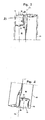
- FIGs. 4 to 5 the difference of a surface of a cutting seat before and after the disclosed exemplary treatment is shown.
- Fig. 4 shows the surface of a cutting seat before the treatment
- Fig. 5 shows the surface of a cutting seat after the treatment.
- substantially all scratches and crack initiations are gone in Fig. 5, which of course improves the fatigue strength.
- a test bar of a steel material of type SS2242 has been produced and then surface treated according to the embodiments disclosed herein. Subsequently, the test bar has been subjected to a fatigue test. The result of the test is seen in Fig. 6, which shows the number of load cycles as a function of the applied force.
- a test bar that has been treated according to embodiments disclosed herein has been designated A; a test bar that only has been subjected to shot peening is designated B; a test bar that solely has been surface hardened by means of nitrocarburizing to a depth of 0.14 mm is designated C; and D is an entirely untreated test bar, i.e., a commonly hardened tool material.
- the surface receives a more even geometry without cracks and scratches.
- the difference between a surface-treated and a not surface-treated tool is seen in Figs. 4 and 5.
- the surface treatment preferably micro blasting/shot peening, gives a contribution of the surface tensions to a level being higher than after the surface hardening alone.
- Another risk of tool breakdown usually is that the material in a tool handle, at the portions that are located a distance axially behind the insert seatings, may be subjected to too unfavorable bending and torsion stresses, which may lead to breakage.
Landscapes
- Chemical & Material Sciences (AREA)
- Engineering & Computer Science (AREA)
- Mechanical Engineering (AREA)
- Crystallography & Structural Chemistry (AREA)
- Materials Engineering (AREA)
- Metallurgy (AREA)
- Organic Chemistry (AREA)
- Physics & Mathematics (AREA)
- Thermal Sciences (AREA)
- Heat Treatment Of Articles (AREA)
- Turning (AREA)
- Drilling Tools (AREA)
Applications Claiming Priority (2)
| Application Number | Priority Date | Filing Date | Title |
|---|---|---|---|
| SE0301450 | 2003-05-16 | ||
| SE0301450A SE525325C2 (sv) | 2003-05-16 | 2003-05-16 | Skärande verktyg för metallbearbetning samt metod vid tillverkning av skärande verktyg |
Publications (2)
| Publication Number | Publication Date |
|---|---|
| EP1477575A1 true EP1477575A1 (de) | 2004-11-17 |
| EP1477575B1 EP1477575B1 (de) | 2011-01-05 |
Family
ID=20291339
Family Applications (1)
| Application Number | Title | Priority Date | Filing Date |
|---|---|---|---|
| EP04445058A Expired - Lifetime EP1477575B1 (de) | 2003-05-16 | 2004-05-13 | Schneidwerkzeug zur Metallbearbeitung und Verfahren zur Herstellung von Schneidwerkzeugen |
Country Status (6)
| Country | Link |
|---|---|
| US (1) | US7270504B2 (de) |
| EP (1) | EP1477575B1 (de) |
| AT (1) | ATE494397T1 (de) |
| DE (1) | DE602004030855D1 (de) |
| SE (1) | SE525325C2 (de) |
| WO (1) | WO2004101846A1 (de) |
Cited By (3)
| Publication number | Priority date | Publication date | Assignee | Title |
|---|---|---|---|---|
| EP2484493A4 (de) * | 2009-09-30 | 2016-03-30 | Sintokogio Ltd | Kugelstrahlbehandlungsverfahren für stahlprodukte |
| EP1867416B1 (de) * | 2005-03-29 | 2018-01-03 | Sumitomo Electric Hardmetal Corp. | Beschichteter schneideinsatz und verfahren zu herstellung eines beschichteten schneideinsatzes |
| USD1009108S1 (en) | 2020-09-21 | 2023-12-26 | Kyocera Unimerco Tooling A/S | Drill |
Families Citing this family (10)
| Publication number | Priority date | Publication date | Assignee | Title |
|---|---|---|---|---|
| SE527684C2 (sv) * | 2004-11-10 | 2006-05-09 | Sandvik Intellectual Property | Skärande verktyg för metallbearbetning samt metod vid tillverkning av skärande verktyg |
| RU2315675C1 (ru) * | 2006-04-14 | 2008-01-27 | Открытое акционерное общество "Институт инновационных технологий в управлении и образовании" | Способ изготовления мелкоразмерного режущего инструмента из быстрорежущей стали |
| DE102006026967A1 (de) * | 2006-06-09 | 2007-12-13 | Rolls-Royce Deutschland Ltd & Co Kg | Verfahren zur Herstellung eines Zerspanwerkzeugs |
| SE532138C2 (sv) * | 2007-07-11 | 2009-11-03 | Sandvik Intellectual Property | Avlångt element för slående bergborrning, förfarande för framställning därav samt användning därav |
| CA2771432A1 (en) | 2009-08-20 | 2011-02-24 | Novartis Ag | Heterocyclic oxime compounds |
| US8647026B2 (en) | 2011-11-23 | 2014-02-11 | Kennametal Inc. | Cutting tool with pocket feature for reducing stress |
| US8621964B2 (en) | 2011-11-23 | 2014-01-07 | Kennametal Inc. | Rotary cutting tool with coolant passage disposed in non-circular recess for reducing stress |
| DE102012017025B4 (de) * | 2012-08-28 | 2018-05-30 | Kennametal Inc. | Werkzeughalter für einen Schneideinsatz und Baugruppe mit einem solchen Werkzeughalter |
| WO2016027207A1 (en) | 2014-08-18 | 2016-02-25 | Bharat Forge Limited | A method of hardening die surfaces |
| US10556278B2 (en) * | 2016-08-16 | 2020-02-11 | Kennametal Inc. | Tool body for a shell end mill and cutting tool |
Citations (6)
| Publication number | Priority date | Publication date | Assignee | Title |
|---|---|---|---|---|
| JPS6393821A (ja) * | 1986-10-07 | 1988-04-25 | Parker Netsushiyori Kogyo Kk | 軟窒化処理品の疲れ強さを向上させる方法 |
| EP0499132A2 (de) * | 1991-02-15 | 1992-08-19 | Mitsubishi Materials Corporation | Schneidwerkzeug |
| EP0506106A1 (de) * | 1991-03-28 | 1992-09-30 | Mitsubishi Materials Corporation | Schneidwerkzeug, Klemmhalter dafür und Verfahren zur Herstellung eines Schneidwerkzeugs |
| EP0536986A1 (de) * | 1991-10-08 | 1993-04-14 | Dowa Mining Co., Ltd. | Verfahren und Vorrichtung zum Oberflächenhärten von Stahl |
| US6058807A (en) * | 1997-01-31 | 2000-05-09 | Mitsubishi Materials Corporation | Cutting tool and method for producing the same |
| EP1219863A2 (de) * | 2000-12-25 | 2002-07-03 | Nissan Motor Company, Limited | Wälzkörper für ein stufenloses Getriebe und dessen Herstellungsverfahren |
Family Cites Families (9)
| Publication number | Priority date | Publication date | Assignee | Title |
|---|---|---|---|---|
| AT220646B (de) | 1959-03-07 | 1962-04-10 | Schoeller Bleckmann Stahlwerke | Stahllegierungen zur Herstellung von Gesteinsbohrwerkzeugen |
| US4674365A (en) * | 1983-07-27 | 1987-06-23 | Spectra Products Corporation | Method for extending the life of a cutting tool |
| JPS60215756A (ja) * | 1984-01-27 | 1985-10-29 | プロセダイン コ−ポレイシヨン | ステンレス鋼の硬化方法 |
| JP2991759B2 (ja) * | 1990-09-28 | 1999-12-20 | 日本電子工業株式会社 | 窒化処理鋼の製造方法 |
| US5609447A (en) * | 1993-11-15 | 1997-03-11 | Rogers Tool Works, Inc. | Surface decarburization of a drill bit |
| DE69519876T2 (de) * | 1995-03-15 | 2001-07-26 | Sunds Defibrator Woodhandling Oy, Pori | Schneidmesser und ein verfahren zur erhöhung der festigkeit des messers |
| JP2839481B2 (ja) | 1996-12-09 | 1998-12-16 | マツダ株式会社 | 熱処理鋼部品及びその製造方法 |
| JP2000005904A (ja) * | 1998-06-18 | 2000-01-11 | Sumitomo Metal Mining Co Ltd | 表面処理鋼系切削工具 |
| US6105374A (en) * | 1998-07-28 | 2000-08-22 | Nu-Bit, Inc. | Process of nitriding metal-containing materials |
-
2003
- 2003-05-16 SE SE0301450A patent/SE525325C2/sv unknown
-
2004
- 2004-05-13 AT AT04445058T patent/ATE494397T1/de not_active IP Right Cessation
- 2004-05-13 DE DE602004030855T patent/DE602004030855D1/de not_active Expired - Lifetime
- 2004-05-13 EP EP04445058A patent/EP1477575B1/de not_active Expired - Lifetime
- 2004-05-13 WO PCT/SE2004/000742 patent/WO2004101846A1/en not_active Ceased
- 2004-05-17 US US10/846,632 patent/US7270504B2/en not_active Expired - Lifetime
Patent Citations (6)
| Publication number | Priority date | Publication date | Assignee | Title |
|---|---|---|---|---|
| JPS6393821A (ja) * | 1986-10-07 | 1988-04-25 | Parker Netsushiyori Kogyo Kk | 軟窒化処理品の疲れ強さを向上させる方法 |
| EP0499132A2 (de) * | 1991-02-15 | 1992-08-19 | Mitsubishi Materials Corporation | Schneidwerkzeug |
| EP0506106A1 (de) * | 1991-03-28 | 1992-09-30 | Mitsubishi Materials Corporation | Schneidwerkzeug, Klemmhalter dafür und Verfahren zur Herstellung eines Schneidwerkzeugs |
| EP0536986A1 (de) * | 1991-10-08 | 1993-04-14 | Dowa Mining Co., Ltd. | Verfahren und Vorrichtung zum Oberflächenhärten von Stahl |
| US6058807A (en) * | 1997-01-31 | 2000-05-09 | Mitsubishi Materials Corporation | Cutting tool and method for producing the same |
| EP1219863A2 (de) * | 2000-12-25 | 2002-07-03 | Nissan Motor Company, Limited | Wälzkörper für ein stufenloses Getriebe und dessen Herstellungsverfahren |
Non-Patent Citations (1)
| Title |
|---|
| PATENT ABSTRACTS OF JAPAN vol. 0123, no. 33 (C - 526) 8 September 1988 (1988-09-08) * |
Cited By (3)
| Publication number | Priority date | Publication date | Assignee | Title |
|---|---|---|---|---|
| EP1867416B1 (de) * | 2005-03-29 | 2018-01-03 | Sumitomo Electric Hardmetal Corp. | Beschichteter schneideinsatz und verfahren zu herstellung eines beschichteten schneideinsatzes |
| EP2484493A4 (de) * | 2009-09-30 | 2016-03-30 | Sintokogio Ltd | Kugelstrahlbehandlungsverfahren für stahlprodukte |
| USD1009108S1 (en) | 2020-09-21 | 2023-12-26 | Kyocera Unimerco Tooling A/S | Drill |
Also Published As
| Publication number | Publication date |
|---|---|
| ATE494397T1 (de) | 2011-01-15 |
| DE602004030855D1 (de) | 2011-02-17 |
| EP1477575B1 (de) | 2011-01-05 |
| SE0301450D0 (sv) | 2003-05-16 |
| WO2004101846A1 (en) | 2004-11-25 |
| SE525325C2 (sv) | 2005-02-01 |
| US7270504B2 (en) | 2007-09-18 |
| US20050002744A1 (en) | 2005-01-06 |
| SE0301450L (sv) | 2004-11-17 |
Similar Documents
| Publication | Publication Date | Title |
|---|---|---|
| EP1657315A1 (de) | Schneidwerkzeug zur Metallbearbeitung und Verfahren zur Herstellung eines Schneidwerkzeugs | |
| EP1477575B1 (de) | Schneidwerkzeug zur Metallbearbeitung und Verfahren zur Herstellung von Schneidwerkzeugen | |
| RU2409454C2 (ru) | Концевая фреза для орбитального фрезерования | |
| CN107322239B (zh) | 一种单向离合器外圈的加工方法 | |
| CN1103258C (zh) | 车削旋转金属工件的方法 | |
| CN101234467A (zh) | 传感器用qs-4弹性体加工工艺 | |
| EP1741507A1 (de) | Spiralbohrer | |
| Brinksmeier et al. | Distortion engineering–identification of causes for dimensional and form deviations of bearing rings | |
| Hosseini et al. | Effects of broaching operations on the integrity of machined surface | |
| CN103796781A (zh) | 可转位式钻头的钻头主体及其制造方法 | |
| US5352067A (en) | Milling cutter clamping wedge with hardened chip surface | |
| da Silva et al. | Enhancing the fatigue strength of AISI 4140 steel through in-situ urea-assisted EDM nitriding | |
| EP4082700A1 (de) | Verfahren zur herstellung eines schneidwerkzeugs | |
| KR101606288B1 (ko) | 벤딩현상 억제를 위한 노치휠 중앙에 열처리강 봉재 또는 초경합금 봉재가 열박음된 다이아몬드 다층 전착 노치휠 제조방법 및 이를 이용한 노치휠 | |
| Axinte et al. | Turning assisted with deep cold rolling—a cost efficient hybrid process for workpiece surface quality enhancement | |
| WO2011024706A1 (ja) | オーステナイト系ステンレス鋼製機器および配管の切削加工方法ならびにこれを用いて切削加工された原子力プラントの機器および配管 | |
| Solis et al. | Influence of a cutting fluid on the surface integrity and fatigue strength of 42CrMo4 drilled parts. | |
| WO2021124698A1 (ja) | 転削加工方法 | |
| JPH08192305A (ja) | スローアウェイチップおよびその製造方法 | |
| US7582170B2 (en) | Method for micromachining metallic materials | |
| JP2000509106A (ja) | 切削工具の製造方法 | |
| CN1988976A (zh) | 刀具 | |
| JPH09136208A (ja) | ろう付けエンドミル | |
| JP2021000719A (ja) | 切削工具および切削方法 | |
| RU2319595C1 (ru) | Комбинированное устройство для шлифования и поверхностного пластического деформирования |
Legal Events
| Date | Code | Title | Description |
|---|---|---|---|
| PUAI | Public reference made under article 153(3) epc to a published international application that has entered the european phase |
Free format text: ORIGINAL CODE: 0009012 |
|
| AK | Designated contracting states |
Kind code of ref document: A1 Designated state(s): AT BE BG CH CY CZ DE DK EE ES FI FR GB GR HU IE IT LI LU MC NL PL PT RO SE SI SK TR |
|
| AX | Request for extension of the european patent |
Extension state: AL HR LT LV MK |
|
| 17P | Request for examination filed |
Effective date: 20050418 |
|
| RAP1 | Party data changed (applicant data changed or rights of an application transferred) |
Owner name: SANDVIK INTELLECTUAL PROPERTY HB |
|
| AKX | Designation fees paid |
Designated state(s): AT BE BG CH CY CZ DE DK EE ES FI FR GB GR HU IE IT LI LU MC NL PL PT RO SE SI SK TR |
|
| RAP1 | Party data changed (applicant data changed or rights of an application transferred) |
Owner name: SANDVIK INTELLECTUAL PROPERTY AB |
|
| GRAP | Despatch of communication of intention to grant a patent |
Free format text: ORIGINAL CODE: EPIDOSNIGR1 |
|
| GRAS | Grant fee paid |
Free format text: ORIGINAL CODE: EPIDOSNIGR3 |
|
| GRAA | (expected) grant |
Free format text: ORIGINAL CODE: 0009210 |
|
| AK | Designated contracting states |
Kind code of ref document: B1 Designated state(s): AT BE BG CH CY CZ DE DK EE ES FI FR GB GR HU IE IT LI LU MC NL PL PT RO SE SI SK TR |
|
| REG | Reference to a national code |
Ref country code: GB Ref legal event code: FG4D |
|
| REG | Reference to a national code |
Ref country code: CH Ref legal event code: EP |
|
| REG | Reference to a national code |
Ref country code: IE Ref legal event code: FG4D |
|
| REF | Corresponds to: |
Ref document number: 602004030855 Country of ref document: DE Date of ref document: 20110217 Kind code of ref document: P |
|
| REG | Reference to a national code |
Ref country code: DE Ref legal event code: R096 Ref document number: 602004030855 Country of ref document: DE Effective date: 20110217 |
|
| REG | Reference to a national code |
Ref country code: NL Ref legal event code: VDEP Effective date: 20110105 |
|
| PG25 | Lapsed in a contracting state [announced via postgrant information from national office to epo] |
Ref country code: SI Free format text: LAPSE BECAUSE OF FAILURE TO SUBMIT A TRANSLATION OF THE DESCRIPTION OR TO PAY THE FEE WITHIN THE PRESCRIBED TIME-LIMIT Effective date: 20110105 |
|
| PG25 | Lapsed in a contracting state [announced via postgrant information from national office to epo] |
Ref country code: GR Free format text: LAPSE BECAUSE OF FAILURE TO SUBMIT A TRANSLATION OF THE DESCRIPTION OR TO PAY THE FEE WITHIN THE PRESCRIBED TIME-LIMIT Effective date: 20110406 Ref country code: SE Free format text: LAPSE BECAUSE OF FAILURE TO SUBMIT A TRANSLATION OF THE DESCRIPTION OR TO PAY THE FEE WITHIN THE PRESCRIBED TIME-LIMIT Effective date: 20110105 Ref country code: PT Free format text: LAPSE BECAUSE OF FAILURE TO SUBMIT A TRANSLATION OF THE DESCRIPTION OR TO PAY THE FEE WITHIN THE PRESCRIBED TIME-LIMIT Effective date: 20110505 Ref country code: ES Free format text: LAPSE BECAUSE OF FAILURE TO SUBMIT A TRANSLATION OF THE DESCRIPTION OR TO PAY THE FEE WITHIN THE PRESCRIBED TIME-LIMIT Effective date: 20110416 |
|
| PG25 | Lapsed in a contracting state [announced via postgrant information from national office to epo] |
Ref country code: FI Free format text: LAPSE BECAUSE OF FAILURE TO SUBMIT A TRANSLATION OF THE DESCRIPTION OR TO PAY THE FEE WITHIN THE PRESCRIBED TIME-LIMIT Effective date: 20110105 Ref country code: AT Free format text: LAPSE BECAUSE OF FAILURE TO SUBMIT A TRANSLATION OF THE DESCRIPTION OR TO PAY THE FEE WITHIN THE PRESCRIBED TIME-LIMIT Effective date: 20110105 Ref country code: NL Free format text: LAPSE BECAUSE OF FAILURE TO SUBMIT A TRANSLATION OF THE DESCRIPTION OR TO PAY THE FEE WITHIN THE PRESCRIBED TIME-LIMIT Effective date: 20110105 Ref country code: BG Free format text: LAPSE BECAUSE OF FAILURE TO SUBMIT A TRANSLATION OF THE DESCRIPTION OR TO PAY THE FEE WITHIN THE PRESCRIBED TIME-LIMIT Effective date: 20110405 Ref country code: CY Free format text: LAPSE BECAUSE OF FAILURE TO SUBMIT A TRANSLATION OF THE DESCRIPTION OR TO PAY THE FEE WITHIN THE PRESCRIBED TIME-LIMIT Effective date: 20110105 Ref country code: PL Free format text: LAPSE BECAUSE OF FAILURE TO SUBMIT A TRANSLATION OF THE DESCRIPTION OR TO PAY THE FEE WITHIN THE PRESCRIBED TIME-LIMIT Effective date: 20110105 Ref country code: BE Free format text: LAPSE BECAUSE OF FAILURE TO SUBMIT A TRANSLATION OF THE DESCRIPTION OR TO PAY THE FEE WITHIN THE PRESCRIBED TIME-LIMIT Effective date: 20110105 |
|
| PG25 | Lapsed in a contracting state [announced via postgrant information from national office to epo] |
Ref country code: EE Free format text: LAPSE BECAUSE OF FAILURE TO SUBMIT A TRANSLATION OF THE DESCRIPTION OR TO PAY THE FEE WITHIN THE PRESCRIBED TIME-LIMIT Effective date: 20110105 Ref country code: DK Free format text: LAPSE BECAUSE OF FAILURE TO SUBMIT A TRANSLATION OF THE DESCRIPTION OR TO PAY THE FEE WITHIN THE PRESCRIBED TIME-LIMIT Effective date: 20110105 |
|
| PLBE | No opposition filed within time limit |
Free format text: ORIGINAL CODE: 0009261 |
|
| STAA | Information on the status of an ep patent application or granted ep patent |
Free format text: STATUS: NO OPPOSITION FILED WITHIN TIME LIMIT |
|
| PG25 | Lapsed in a contracting state [announced via postgrant information from national office to epo] |
Ref country code: RO Free format text: LAPSE BECAUSE OF FAILURE TO SUBMIT A TRANSLATION OF THE DESCRIPTION OR TO PAY THE FEE WITHIN THE PRESCRIBED TIME-LIMIT Effective date: 20110105 Ref country code: SK Free format text: LAPSE BECAUSE OF FAILURE TO SUBMIT A TRANSLATION OF THE DESCRIPTION OR TO PAY THE FEE WITHIN THE PRESCRIBED TIME-LIMIT Effective date: 20110105 Ref country code: CZ Free format text: LAPSE BECAUSE OF FAILURE TO SUBMIT A TRANSLATION OF THE DESCRIPTION OR TO PAY THE FEE WITHIN THE PRESCRIBED TIME-LIMIT Effective date: 20110105 |
|
| 26N | No opposition filed |
Effective date: 20111006 |
|
| PG25 | Lapsed in a contracting state [announced via postgrant information from national office to epo] |
Ref country code: MC Free format text: LAPSE BECAUSE OF NON-PAYMENT OF DUE FEES Effective date: 20110531 |
|
| REG | Reference to a national code |
Ref country code: CH Ref legal event code: PL |
|
| PG25 | Lapsed in a contracting state [announced via postgrant information from national office to epo] |
Ref country code: CH Free format text: LAPSE BECAUSE OF NON-PAYMENT OF DUE FEES Effective date: 20110531 Ref country code: LI Free format text: LAPSE BECAUSE OF NON-PAYMENT OF DUE FEES Effective date: 20110531 |
|
| REG | Reference to a national code |
Ref country code: DE Ref legal event code: R097 Ref document number: 602004030855 Country of ref document: DE Effective date: 20111006 |
|
| REG | Reference to a national code |
Ref country code: IE Ref legal event code: MM4A |
|
| PG25 | Lapsed in a contracting state [announced via postgrant information from national office to epo] |
Ref country code: IE Free format text: LAPSE BECAUSE OF NON-PAYMENT OF DUE FEES Effective date: 20110513 |
|
| PG25 | Lapsed in a contracting state [announced via postgrant information from national office to epo] |
Ref country code: LU Free format text: LAPSE BECAUSE OF NON-PAYMENT OF DUE FEES Effective date: 20110513 |
|
| PG25 | Lapsed in a contracting state [announced via postgrant information from national office to epo] |
Ref country code: TR Free format text: LAPSE BECAUSE OF FAILURE TO SUBMIT A TRANSLATION OF THE DESCRIPTION OR TO PAY THE FEE WITHIN THE PRESCRIBED TIME-LIMIT Effective date: 20110105 |
|
| PG25 | Lapsed in a contracting state [announced via postgrant information from national office to epo] |
Ref country code: HU Free format text: LAPSE BECAUSE OF FAILURE TO SUBMIT A TRANSLATION OF THE DESCRIPTION OR TO PAY THE FEE WITHIN THE PRESCRIBED TIME-LIMIT Effective date: 20110105 |
|
| REG | Reference to a national code |
Ref country code: FR Ref legal event code: PLFP Year of fee payment: 13 |
|
| REG | Reference to a national code |
Ref country code: FR Ref legal event code: PLFP Year of fee payment: 14 |
|
| REG | Reference to a national code |
Ref country code: FR Ref legal event code: PLFP Year of fee payment: 15 |
|
| PGFP | Annual fee paid to national office [announced via postgrant information from national office to epo] |
Ref country code: DE Payment date: 20190430 Year of fee payment: 16 Ref country code: IT Payment date: 20190527 Year of fee payment: 16 |
|
| PGFP | Annual fee paid to national office [announced via postgrant information from national office to epo] |
Ref country code: FR Payment date: 20190429 Year of fee payment: 16 |
|
| PGFP | Annual fee paid to national office [announced via postgrant information from national office to epo] |
Ref country code: GB Payment date: 20190508 Year of fee payment: 16 |
|
| REG | Reference to a national code |
Ref country code: DE Ref legal event code: R119 Ref document number: 602004030855 Country of ref document: DE |
|
| GBPC | Gb: european patent ceased through non-payment of renewal fee |
Effective date: 20200513 |
|
| PG25 | Lapsed in a contracting state [announced via postgrant information from national office to epo] |
Ref country code: FR Free format text: LAPSE BECAUSE OF NON-PAYMENT OF DUE FEES Effective date: 20200531 Ref country code: GB Free format text: LAPSE BECAUSE OF NON-PAYMENT OF DUE FEES Effective date: 20200513 |
|
| PG25 | Lapsed in a contracting state [announced via postgrant information from national office to epo] |
Ref country code: DE Free format text: LAPSE BECAUSE OF NON-PAYMENT OF DUE FEES Effective date: 20201201 |
|
| PG25 | Lapsed in a contracting state [announced via postgrant information from national office to epo] |
Ref country code: IT Free format text: LAPSE BECAUSE OF NON-PAYMENT OF DUE FEES Effective date: 20200513 |