EP1477696A2 - Sealed axially displaceable slip joint - Google Patents
Sealed axially displaceable slip joint Download PDFInfo
- Publication number
- EP1477696A2 EP1477696A2 EP04252740A EP04252740A EP1477696A2 EP 1477696 A2 EP1477696 A2 EP 1477696A2 EP 04252740 A EP04252740 A EP 04252740A EP 04252740 A EP04252740 A EP 04252740A EP 1477696 A2 EP1477696 A2 EP 1477696A2
- Authority
- EP
- European Patent Office
- Prior art keywords
- shaft
- seals
- slip joint
- seal
- secured
- Prior art date
- Legal status (The legal status is an assumption and is not a legal conclusion. Google has not performed a legal analysis and makes no representation as to the accuracy of the status listed.)
- Withdrawn
Links
- 239000003566 sealing material Substances 0.000 claims abstract description 7
- 239000004519 grease Substances 0.000 claims abstract description 5
- 238000007789 sealing Methods 0.000 claims description 19
- 239000000356 contaminant Substances 0.000 description 14
- 230000005540 biological transmission Effects 0.000 description 7
- 239000000463 material Substances 0.000 description 3
- 230000000712 assembly Effects 0.000 description 2
- 238000000429 assembly Methods 0.000 description 2
- 238000006073 displacement reaction Methods 0.000 description 2
- 238000003754 machining Methods 0.000 description 2
- 230000004323 axial length Effects 0.000 description 1
- 230000000295 complement effect Effects 0.000 description 1
- 238000011109 contamination Methods 0.000 description 1
- 230000007797 corrosion Effects 0.000 description 1
- 238000005260 corrosion Methods 0.000 description 1
- 230000008878 coupling Effects 0.000 description 1
- 238000010168 coupling process Methods 0.000 description 1
- 238000005859 coupling reaction Methods 0.000 description 1
- -1 dirt Substances 0.000 description 1
- 239000013536 elastomeric material Substances 0.000 description 1
- 238000003780 insertion Methods 0.000 description 1
- 230000037431 insertion Effects 0.000 description 1
- JEIPFZHSYJVQDO-UHFFFAOYSA-N iron(III) oxide Inorganic materials O=[Fe]O[Fe]=O JEIPFZHSYJVQDO-UHFFFAOYSA-N 0.000 description 1
- 239000002184 metal Substances 0.000 description 1
- 230000002093 peripheral effect Effects 0.000 description 1
- 238000005096 rolling process Methods 0.000 description 1
- XLYOFNOQVPJJNP-UHFFFAOYSA-N water Substances O XLYOFNOQVPJJNP-UHFFFAOYSA-N 0.000 description 1
Images

Classifications
-
- F—MECHANICAL ENGINEERING; LIGHTING; HEATING; WEAPONS; BLASTING
- F16—ENGINEERING ELEMENTS AND UNITS; GENERAL MEASURES FOR PRODUCING AND MAINTAINING EFFECTIVE FUNCTIONING OF MACHINES OR INSTALLATIONS; THERMAL INSULATION IN GENERAL
- F16D—COUPLINGS FOR TRANSMITTING ROTATION; CLUTCHES; BRAKES
- F16D3/00—Yielding couplings, i.e. with means permitting movement between the connected parts during the drive
- F16D3/84—Shrouds, e.g. casings, covers; Sealing means specially adapted therefor
- F16D3/843—Shrouds, e.g. casings, covers; Sealing means specially adapted therefor enclosed covers
- F16D3/848—Shrouds, e.g. casings, covers; Sealing means specially adapted therefor enclosed covers allowing relative movement of joint parts due to sliding between parts of the cover
-
- F—MECHANICAL ENGINEERING; LIGHTING; HEATING; WEAPONS; BLASTING
- F16—ENGINEERING ELEMENTS AND UNITS; GENERAL MEASURES FOR PRODUCING AND MAINTAINING EFFECTIVE FUNCTIONING OF MACHINES OR INSTALLATIONS; THERMAL INSULATION IN GENERAL
- F16D—COUPLINGS FOR TRANSMITTING ROTATION; CLUTCHES; BRAKES
- F16D3/00—Yielding couplings, i.e. with means permitting movement between the connected parts during the drive
- F16D3/02—Yielding couplings, i.e. with means permitting movement between the connected parts during the drive adapted to specific functions
- F16D3/06—Yielding couplings, i.e. with means permitting movement between the connected parts during the drive adapted to specific functions specially adapted to allow axial displacement
-
- F—MECHANICAL ENGINEERING; LIGHTING; HEATING; WEAPONS; BLASTING
- F16—ENGINEERING ELEMENTS AND UNITS; GENERAL MEASURES FOR PRODUCING AND MAINTAINING EFFECTIVE FUNCTIONING OF MACHINES OR INSTALLATIONS; THERMAL INSULATION IN GENERAL
- F16D—COUPLINGS FOR TRANSMITTING ROTATION; CLUTCHES; BRAKES
- F16D2300/00—Special features for couplings or clutches
- F16D2300/06—Lubrication details not provided for in group F16D13/74
Definitions
- This invention relates in general to driveshaft assemblies, such as those commonly found in the drive train systems of most vehicles.
- this invention relates to an improved seal arrangement for use with a slip joint in such a driveshaft assembly.
- Drive train systems are widely used for generating power from a source and for transferring such power from the source to a driven mechanism.
- the source generates rotational power, and such rotational power is transferred from the source to a rotatably driven mechanism.
- an engine/transmission assembly generates rotational power, and such rotational power is transferred from an output shaft of the engine/transmission assembly through a driveshaft assembly to an input shaft of an axle assembly so as to rotatably drive the wheels of the vehicle.
- a typical driveshaft assembly includes a hollow cylindrical driveshaft tube having a pair of end fittings, such as a pair of tube yokes, secured to the front and rear ends thereof.
- the front end fitting forms a portion of a front universal joint that connects the output shaft of the engine/transmission assembly to the front end of the driveshaft tube.
- the rear end fitting forms a portion of a rear universal joint that connects the rear end of the driveshaft tube to the input shaft of the axle assembly.
- the front and rear universal joints provide a rotational driving connection from the output shaft of the engine/transmission assembly through the driveshaft tube to the input shaft of the axle assembly, while accommodating a limited amount of angular misalignment between the rotational axes of these three shafts.
- a typical slip joint includes first and second members that have respective structures formed thereon that cooperate with one another for concurrent rotational movement, while permitting a limited amount of axial movement to occur therebetween.
- Two types of slip joints are commonly used in conventional driveshaft assemblies, namely, a sliding spline type and a rolling ball spline type.
- a typical sliding spline type of slip joint includes male and female members having respective pluralities of splines formed thereon.
- the male member is generally cylindrical in shape and has a plurality of outwardly extending splines formed on the outer surface thereof.
- the male member may be formed integrally with or secured to an end of the driveshaft assembly described above.
- the female member is generally hollow and cylindrical in shape and has a plurality of inwardly extending splines formed on the inner surface thereof.
- the female member may be formed integrally with or secured to a yoke that forms a portion of one of the universal joints described above.
- the male member is inserted within the female member such that the outwardly extending splines of the male member cooperate with the inwardly extending splines of the female member.
- the male and female members are connected together for concurrent rotational movement.
- the outwardly extending splines of the male member can slide relative to the inwardly extending splines of the female member to allow a limited amount of relative axial movement to occur between the engine/transmission assembly and the axle assembly of the drive train system.
- the driveshaft assembly is located on the underside of the vehicle where contaminants, such as dirt, water, and the like, could enter the assembly at the slip joint if it were not adequately sealed.
- the area on the surface of a driveshaft assembly, where the sleeve shaft terminates and ceases to overlap the outer surface of the inner shaft, is highly susceptible to the entrance of contaminants, which can interfere with axial movement of the sleeve shaft relative to the inner shaft. These contaminants can also cause corrosion and rust on the components of the driveshaft assembly.
- Booted seals are also susceptible to damage due to the high temperature environment in which they operate. It is preferable to provide a reliable, movement-tolerant seal against the entrance of contaminants, a seal that can endure a high temperature environment and is not susceptible to damage, such as the splitting and tearing that may occur with a booted seal.
- This invention provides a seal for a slip joint for a first component and second component having relative axial displacement.
- the invention includes a hollow cylindrical can surrounding and spaced radially from the first component, extending axially from and secured to the second component, and a seal secured to the first component and resiliently contacting the can, the first component and can defining an axial passage having a constricted opening that inhibits entry of foreign material and its travel toward the seal.
- the present invention in another embodiment applicable to a driveshaft of a motor vehicle, includes a first shaft, having a surface formed with axially directed spline teeth, a second shaft arranged substantially co-axially with the first shaft and having a surface formed with axially directed spline teeth engaged with the spine teeth of the first shaft, the first and second shafts being mutually displaceable, a can surrounding and spaced radially from the first shaft and secured to the second shaft, a sealing surface, and a seal assembly secured to the first shaft and resiliently contacting the sealing surface.
- the can protects the seal from the environment.
- a seal is formed with complementary fingers, which provide a space for holding waterproof grease packed between the seal fingers, thereby providing additional sealing.
- the surface finish of a sealing surface on the can provides adequate sealing and seal assures lip durability. This sealing surface eliminates the need for machining a seal surface on the sleeve shaft. An added labyrinth between the sleeve shaft can resist contamination entry to the seal.
- a sliding spline type of slip joint including a seal arrangement in accordance with this invention is generally conventional in the art and can, for example, be used in a driveshaft assembly of the type described above to transmit rotational from a source to a driven mechanism, such as from an output shaft of a vehicular transmission to an input shaft of an axle assembly.
- a driveshaft assembly of the type described above to transmit rotational from a source to a driven mechanism, such as from an output shaft of a vehicular transmission to an input shaft of an axle assembly.
- the scope of this invention is not intended to be limited for use with the specific structure for the slip joint illustrated in Fig. 1 or with vehicle drive train systems in general. On the contrary, as will become apparent below, this invention may be used in any desired environment for the purposes described below.
- the illustrated slip joint includes a first inner shaft 10 that extends axially from a yoke that can, for example, form a portion of a universal joint in the driveshaft assembly, such as described above.
- the illustrated portion of the universal joint is a conventional cardan type of joint. However, this invention may, if desired, be used with any type of universal joint, including constant velocity joints, rubber couplings, and the like.
- the inner shaft 10 is formed or otherwise provided with a plurality axially-directed, angularly-spaced spline teeth 16 that extend radially outwardly from an outer surface thereof.
- the slip joint also includes an outer sleeve shaft 22 that is axially aligned with and surrounds the inner shaft 10.
- the outer sleeve shaft 22 is formed or otherwise provided with a plurality of axially-directed, angularly-spaced spline teeth 24 that extend radially inwardly from an inner surface thereof.
- the slip joint is assembled by inserting the inner shaft 10 within the outer sleeve shaft 22 such that each of the external spline teeth 16 on the inner shaft 10 is located between adjacent ones of the internal spline teeth 24 on the outer sleeve shaft 22.
- the inner shaft 10 and the outer sleeve shaft 22 are engaged mutually for rotation and to transmit torque. Due to the engagement of the external and internal spline teeth 16 and 24, respectively, the inner shaft 10 and the outer sleeve shaft 22 can also slide axially relative to one another, at least to a limited extent.
- One end 34 of that annular, axially extending space is located between an end 36 of outer sleeve shaft 22 and an end 38 of a shoulder 40 formed on the outer surface of inner shaft 10.
- the slip joint can, if desired, be supported for rotation by a conventional bearing assembly 26.
- the illustrated bearing assembly 26 includes an inner race 32 that engages the outer surface of inner shaft 10 and an outer race 33 that can be engaged with a support surface (not shown), such as a portion of a chassis of the vehicle.
- a support surface such as a portion of a chassis of the vehicle.
- another bearing can be provided to rotatably support a second portion of the slip joint at another location.
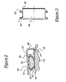
- a seal assembly is provided to prevent the entry of contaminants into the one end 34 of the annular, axially extending space wherein the.external and internal spline teeth 16 and 24 of the inner shaft 10 and the outer sleeve shaft 22, respectively, engage one another.
- the seal assembly includes a seal can 44 having a hollow cylindrical portion 46 that extends axially about a relatively lengthy portion of the outer surface of the outer sleeve shaft 22.
- a first end of the seal can 44 is formed having a reduced diameter flange portion 50, which can be provided to press fit or otherwise support the seal can 44 on an outer surface of the shoulder or other portion of the inner shaft 10.
- a second end of the seal can 44 is open and extends about a shoulder 48 provided on the outer surface of the outer sleeve shaft 22.
- the enlarged diameter shoulder 48 cooperates with an inner surface 52 of the seal can 44 to provide a constricted space that resists the entry of contaminants therein.
- the seal can 44 is formed from a stamped metallic or other relatively rigid material.
- the inner surface 52 of the seal can 44 is preferably formed in such a manner as to provide a smooth sealing surface, for a purpose that will be explained in detail below.
- the seal assembly also includes a pair of seals 60 and 62 that are located in an annular space that is defined between an outer surface 56 of the outer sleeve shaft 22 and the inner surface 52 of seal can 44.
- the seals 60 and 62 are preferably molded or otherwise secured to an outer surface of a backing member 66.
- the backing member 66 is generally hollow and cylindrical in shape and may, for example, be press fit on the outer surface 56 of the outer sleeve shaft 22. If desired, the backing member 66 can include a radially extending flange portion 68 that extends partially over the end 36 of outer sleeve shaft 22.
- a chamfer 70 may be formed on the outer peripheral edge of such end 36.
- the flange portion 68 can be provided to precisely position the backing member 66 and the seals 60 and 62 relative to the outer sleeve shaft 22.
- Each of the seals 60 and 62 is preferably formed from a flexible material, such as rubber or other conventional elastomeric material.
- the seals 60 and 62 project radially outwardly from the backing member 66 and terminate at respective sealing lips 76 and 78.
- the sealing lips 76 and 78 are sized to be urged into sealing engagement with the inner surface 52 of the seal can 44 with a relative light, elastic pre-loading force.
- the seals 60 and 62 are generally concave in shape, having radially innermost and outermost ends that are located closer to one another than their radially intermediate portions.
- each of the seals 60 and 62 has a generally V-shaped cross sectional shape, with the open ends of the V-shaped seals 60 and 62 facing toward one another and the closed ends thereof facing away from one another.
- the seals 60 and 62 may be formed having any desired shape or shapes.
- the seals 60 and 62 are axially spaced apart from one another so as to define an annular space therebetween.
- This annular space is preferably filled with a sealing material 64 to further prevent the passage of contaminants therethrough.
- Any desired sealing material may used, such as a conventional waterproof grease.
- the inner shaft 10 and the outer sleeve shaft 22 of the slip joint are rotatably driven to transfer rotational power from the source to the driven device.
- the hollow cylindrical portion 46 of the seal can 44 extends axially about a relatively lengthy portion of the outer surface of the outer sleeve shaft 22.
- the enlarged diameter shoulder 48 provided on the outer surface 56 of the outer sleeve shaft 22 cooperates with the inner surface 52 of the second, open end of the seal can 44 to create a constricted space that resists the entry of contaminants therein. Thus, most of the contaminants that are encountered during operation are prevented from entering into the slip joint by this constricted space.
- any such contaminants that do enter the slip joint through this constricted space must then pass along the axial length of the seal can 44 before reaching the seals 60 and 62.
- the sealing lips 76 and 78 of the seals 60 and 62 are urged into sealing engagement with the inner surface 52 of the seal can 44.
- the passage of the contaminants through the seals 60 and 62 is effectively deterred.
- the presence of the sealing material 64 in the annular space between the seals 60 and 62 further deters the passage of the contaminants therethrough.
- the inner shaft 10 and the outer sleeve shaft 22 of the slip joint may move axially relative to one another.
- the seal can 44 (which is connected for movement with the inner shaft 10) moves axially relative to the seals 60 and 62 (which are connected for movement with the outer sleeve shaft 22.
- the sealing lips 76 and 78 of the seals 60 and 62 slide along the inner surface 52 of the seal can 44.
- the inner surface 52 of the seal can 44 is preferably formed in such a manner as to provide a smooth sealing surface.
- the seal can 44 protects the seals 60 and 62 from the environment, and further functions to minimize the amount of contaminants that reach the seals 60 and 62.
- the spaced apart seals 60 and 62 provide an annular space for retaining a sealing material 64, such as a waterproof grease, packed therebetween, thereby providing additional sealing.
- the surface finish of the inner sealing surface 52 of the seal can 44 provides adequate sealing, promotes seal lip durability, and eliminates the need for seal surface machining on the outer sleeve shaft 22.
Landscapes
- Engineering & Computer Science (AREA)
- General Engineering & Computer Science (AREA)
- Mechanical Engineering (AREA)
- Shafts, Cranks, Connecting Bars, And Related Bearings (AREA)
- Sealing Devices (AREA)
- Motor Power Transmission Devices (AREA)
Applications Claiming Priority (2)
| Application Number | Priority Date | Filing Date | Title |
|---|---|---|---|
| US436885 | 2003-05-13 | ||
| US10/436,885 US6863613B2 (en) | 2003-05-13 | 2003-05-13 | Sealed axially displaceable slip joint |
Publications (1)
| Publication Number | Publication Date |
|---|---|
| EP1477696A2 true EP1477696A2 (en) | 2004-11-17 |
Family
ID=33029783
Family Applications (1)
| Application Number | Title | Priority Date | Filing Date |
|---|---|---|---|
| EP04252740A Withdrawn EP1477696A2 (en) | 2003-05-13 | 2004-05-12 | Sealed axially displaceable slip joint |
Country Status (5)
| Country | Link |
|---|---|
| US (1) | US6863613B2 (pt) |
| EP (1) | EP1477696A2 (pt) |
| CN (1) | CN1550687A (pt) |
| AU (1) | AU2004202008A1 (pt) |
| BR (1) | BRPI0401741A (pt) |
Families Citing this family (15)
| Publication number | Priority date | Publication date | Assignee | Title |
|---|---|---|---|---|
| US7354216B2 (en) * | 2005-04-12 | 2008-04-08 | Honeywell International, Inc. | Grease seal cup to retain lubrication for life extension in existing splined joint |
| WO2007108234A1 (ja) * | 2006-03-23 | 2007-09-27 | Ihi Corporation | 過給機の高速回転軸 |
| JP4671177B2 (ja) * | 2006-06-02 | 2011-04-13 | 株式会社Ihi | 電動過給機 |
| US8152489B2 (en) * | 2006-08-18 | 2012-04-10 | Ihi Corporation | Motor-driven supercharger |
| CN101506489B (zh) * | 2006-08-18 | 2011-11-16 | 株式会社Ihi | 电动增压器 |
| DE502008002779D1 (de) * | 2007-10-25 | 2011-04-14 | Schaeffler Technologies Gmbh | Drehmomentübertragungseinrichtung |
| WO2009095985A1 (ja) * | 2008-01-28 | 2009-08-06 | Ihi Corporation | 過給機 |
| DE102009052381A1 (de) * | 2009-11-09 | 2011-05-26 | Schwing Gmbh | Dichtungselement, insbesondere für Dickstofffördervorrichtungen |
| JP5516157B2 (ja) * | 2010-07-06 | 2014-06-11 | 株式会社ジェイテクト | 動力伝達軸装置 |
| CN102767577B (zh) * | 2012-07-11 | 2015-04-01 | 南京冠盛汽配有限公司 | 低震动自动滑移补偿复式花键万向节 |
| US20150075897A1 (en) * | 2013-09-12 | 2015-03-19 | Sonnax Industries, Inc. | Slip Yoke Assembly For Automotive Drive Train |
| JP6497997B2 (ja) * | 2015-03-19 | 2019-04-10 | 日立オートモティブシステムズ株式会社 | 動力伝達軸 |
| US10323692B2 (en) * | 2017-01-16 | 2019-06-18 | Arvinmeritor Technology, Llc | Slip yoke assembly |
| EP3767136B1 (en) * | 2018-03-14 | 2024-10-23 | Sealink Corp. | Rotating sealing device |
| US11767050B2 (en) * | 2020-04-30 | 2023-09-26 | Steering Solutions Ip Holding Corporation | Plastic injected rigid splined shaft connection |
Family Cites Families (13)
| Publication number | Priority date | Publication date | Assignee | Title |
|---|---|---|---|---|
| US3123990A (en) | 1964-03-10 | Lubrication arrangement for tele- | ||
| US2867482A (en) * | 1958-01-31 | 1959-01-06 | Joseph J Schmidt | Piston rings |
| US3349973A (en) * | 1964-02-04 | 1967-10-31 | Chemetron Corp | Receptacle filling machines |
| US3248900A (en) | 1964-02-13 | 1966-05-03 | Twin Disc Clutch Co | Anti-friction slip joint |
| CH472573A (de) * | 1967-03-22 | 1969-05-15 | Eisenegger Edwin | Einrichtung zur Schmierung von Kolbenmaschinen |
| DE2308820C3 (de) | 1973-02-22 | 1984-09-20 | Gelenkwellenbau Gmbh, 4300 Essen | Axial bewegliche Lippendichtung für die Keilwellennabe einer Gelenkwelle |
| US4094512A (en) | 1976-07-14 | 1978-06-13 | Crane Packing Limited | Shaft seals |
| US4427201A (en) * | 1982-08-30 | 1984-01-24 | Allis-Chalmers Corporation | Double seal having vibration damping and lubricating means |
| US4592556A (en) | 1984-12-17 | 1986-06-03 | Dana Corporation | Slip joint seal assembly |
| WO1991013277A1 (de) | 1990-02-26 | 1991-09-05 | Zahnradfabrik Friedrichshafen Ag | Dichtungsanordnung |
| US5230658A (en) * | 1992-04-06 | 1993-07-27 | Burton Robert A | Driveshaft with slip joint seal |
| CA2130786A1 (en) | 1994-06-30 | 1995-12-31 | Robert A. Burton | Driveshaft with sealed slip joint seal |
| US5853177A (en) | 1996-05-28 | 1998-12-29 | Meritor Heavy Vehicle Systems, Llc | Drive transmission sealing device |
-
2003
- 2003-05-13 US US10/436,885 patent/US6863613B2/en not_active Expired - Fee Related
-
2004
- 2004-05-12 BR BR0401741-2A patent/BRPI0401741A/pt not_active Application Discontinuation
- 2004-05-12 EP EP04252740A patent/EP1477696A2/en not_active Withdrawn
- 2004-05-12 AU AU2004202008A patent/AU2004202008A1/en not_active Abandoned
- 2004-05-13 CN CNA2004100451784A patent/CN1550687A/zh active Pending
Also Published As
| Publication number | Publication date |
|---|---|
| BRPI0401741A (pt) | 2005-01-18 |
| CN1550687A (zh) | 2004-12-01 |
| AU2004202008A1 (en) | 2004-12-02 |
| US20040229703A1 (en) | 2004-11-18 |
| US6863613B2 (en) | 2005-03-08 |
Similar Documents
| Publication | Publication Date | Title |
|---|---|---|
| US6863613B2 (en) | Sealed axially displaceable slip joint | |
| US8864591B2 (en) | Propeller shaft and constant velocity universal joint used therein | |
| US5961388A (en) | Seal for slip yoke assembly | |
| CN108474419B (zh) | 等速万向联轴器 | |
| US7007362B2 (en) | Method of forming a slip joint | |
| US7534172B2 (en) | Direct torque flow constant velocity joint having a non-rotating boot | |
| GB2171173A (en) | Boot for universal joint | |
| JP2019515201A (ja) | 等速ジョイント用ブーツアセンブリ | |
| US11698110B2 (en) | Direct pinion mount joint assembly | |
| US7044860B2 (en) | Slip joint for vehicle driveshaft assembly | |
| US6926612B2 (en) | Joint assembly and sealing boot | |
| US6158916A (en) | Universal joint connector | |
| US7090584B2 (en) | High temperature slip spline boot | |
| US7052398B2 (en) | Pressure regulator assembly for use with a slip joint in a driveshaft assembly | |
| US7338378B1 (en) | Retainer for universal joint bearing cups | |
| JPH11227478A (ja) | 自動車用プロペラシャフト | |
| EP1286067B1 (en) | Pressure regulator assembly for use with a slip joint in a driveshaft assembly | |
| US20200284301A1 (en) | Constant velocity universal joint | |
| JP5118149B2 (ja) | 直接トルクフロー等速ジョイント雄スプライン連結部 | |
| JP2019056455A (ja) | 等速自在継手 | |
| JP2010025207A (ja) | 等速自在継手 | |
| RU46717U1 (ru) | Привод раздаточной коробки | |
| US20070123357A1 (en) | Direct torque flow constant velocity joint with male connector | |
| AU2006201814A1 (en) | Method of manufacturing a driveshaft assembly | |
| CN108884877B (zh) | 用于等速万向节的护套和保持构件组件 |
Legal Events
| Date | Code | Title | Description |
|---|---|---|---|
| PUAI | Public reference made under article 153(3) epc to a published international application that has entered the european phase |
Free format text: ORIGINAL CODE: 0009012 |
|
| AK | Designated contracting states |
Kind code of ref document: A2 Designated state(s): AT BE BG CH CY CZ DE DK EE ES FI FR GB GR HU IE IT LI LU MC NL PL PT RO SE SI SK TR |
|
| AX | Request for extension of the european patent |
Extension state: AL HR LT LV MK |
|
| STAA | Information on the status of an ep patent application or granted ep patent |
Free format text: STATUS: THE APPLICATION IS DEEMED TO BE WITHDRAWN |
|
| 18D | Application deemed to be withdrawn |
Effective date: 20071201 |