EP1477762A2 - Thermosyphon und Verfahren zu dessen Herstellung - Google Patents
Thermosyphon und Verfahren zu dessen Herstellung Download PDFInfo
- Publication number
- EP1477762A2 EP1477762A2 EP04076228A EP04076228A EP1477762A2 EP 1477762 A2 EP1477762 A2 EP 1477762A2 EP 04076228 A EP04076228 A EP 04076228A EP 04076228 A EP04076228 A EP 04076228A EP 1477762 A2 EP1477762 A2 EP 1477762A2
- Authority
- EP
- European Patent Office
- Prior art keywords
- thermosyphon
- lid
- base
- evaporator
- condenser
- Prior art date
- Legal status (The legal status is an assumption and is not a legal conclusion. Google has not performed a legal analysis and makes no representation as to the accuracy of the status listed.)
- Withdrawn
Links
Images



Classifications
-
- F—MECHANICAL ENGINEERING; LIGHTING; HEATING; WEAPONS; BLASTING
- F28—HEAT EXCHANGE IN GENERAL
- F28D—HEAT-EXCHANGE APPARATUS, NOT PROVIDED FOR IN ANOTHER SUBCLASS, IN WHICH THE HEAT-EXCHANGE MEDIA DO NOT COME INTO DIRECT CONTACT
- F28D15/00—Heat-exchange apparatus with the intermediate heat-transfer medium in closed tubes passing into or through the conduit walls ; Heat-exchange apparatus employing intermediate heat-transfer medium or bodies
- F28D15/02—Heat-exchange apparatus with the intermediate heat-transfer medium in closed tubes passing into or through the conduit walls ; Heat-exchange apparatus employing intermediate heat-transfer medium or bodies in which the medium condenses and evaporates, e.g. heat pipes
- F28D15/0233—Heat-exchange apparatus with the intermediate heat-transfer medium in closed tubes passing into or through the conduit walls ; Heat-exchange apparatus employing intermediate heat-transfer medium or bodies in which the medium condenses and evaporates, e.g. heat pipes the conduits having a particular shape, e.g. non-circular cross-section, annular
-
- F—MECHANICAL ENGINEERING; LIGHTING; HEATING; WEAPONS; BLASTING
- F28—HEAT EXCHANGE IN GENERAL
- F28D—HEAT-EXCHANGE APPARATUS, NOT PROVIDED FOR IN ANOTHER SUBCLASS, IN WHICH THE HEAT-EXCHANGE MEDIA DO NOT COME INTO DIRECT CONTACT
- F28D15/00—Heat-exchange apparatus with the intermediate heat-transfer medium in closed tubes passing into or through the conduit walls ; Heat-exchange apparatus employing intermediate heat-transfer medium or bodies
- F28D15/02—Heat-exchange apparatus with the intermediate heat-transfer medium in closed tubes passing into or through the conduit walls ; Heat-exchange apparatus employing intermediate heat-transfer medium or bodies in which the medium condenses and evaporates, e.g. heat pipes
- F28D15/0266—Heat-exchange apparatus with the intermediate heat-transfer medium in closed tubes passing into or through the conduit walls ; Heat-exchange apparatus employing intermediate heat-transfer medium or bodies in which the medium condenses and evaporates, e.g. heat pipes with separate evaporating and condensing chambers connected by at least one conduit; Loop-type heat pipes; with multiple or common evaporating or condensing chambers
-
- F—MECHANICAL ENGINEERING; LIGHTING; HEATING; WEAPONS; BLASTING
- F28—HEAT EXCHANGE IN GENERAL
- F28F—DETAILS OF HEAT-EXCHANGE AND HEAT-TRANSFER APPARATUS, OF GENERAL APPLICATION
- F28F3/00—Plate-like or laminated elements; Assemblies of plate-like or laminated elements
- F28F3/02—Elements or assemblies thereof with means for increasing heat-transfer area, e.g. with fins, with recesses, with corrugations
- F28F3/04—Elements or assemblies thereof with means for increasing heat-transfer area, e.g. with fins, with recesses, with corrugations the means being integral with the element
- F28F3/048—Elements or assemblies thereof with means for increasing heat-transfer area, e.g. with fins, with recesses, with corrugations the means being integral with the element in the form of ribs integral with the element or local variations in thickness of the element, e.g. grooves, microchannels
-
- H—ELECTRICITY
- H10—SEMICONDUCTOR DEVICES; ELECTRIC SOLID-STATE DEVICES NOT OTHERWISE PROVIDED FOR
- H10W—GENERIC PACKAGES, INTERCONNECTIONS, CONNECTORS OR OTHER CONSTRUCTIONAL DETAILS OF DEVICES COVERED BY CLASS H10
- H10W40/00—Arrangements for thermal protection or thermal control
- H10W40/70—Fillings or auxiliary members in containers or in encapsulations for thermal protection or control
- H10W40/73—Fillings or auxiliary members in containers or in encapsulations for thermal protection or control for cooling by change of state
-
- F—MECHANICAL ENGINEERING; LIGHTING; HEATING; WEAPONS; BLASTING
- F28—HEAT EXCHANGE IN GENERAL
- F28F—DETAILS OF HEAT-EXCHANGE AND HEAT-TRANSFER APPARATUS, OF GENERAL APPLICATION
- F28F2255/00—Heat exchanger elements made of materials having special features or resulting from particular manufacturing processes
- F28F2255/16—Heat exchanger elements made of materials having special features or resulting from particular manufacturing processes extruded
Definitions
- the present invention relates to thermosyphons, in particular for use in the cooling of electronic components.
- Thermal management is a key issue in the design of the electronic package.
- the proper design insures that the peak temperatures remain within a specified operating range to produce a reliable module.
- the main objective is to maintain the semiconductor device junction temperature below the maximum operating temperature of the module.
- Design challenges included in heat removal are higher circuit densities, close proximity of adjacent devices or components, low thermal conductivity substrates, inner layers of metal forming the interconnect, and the thermal resistance of heat sink systems.
- any heat transfer design is to allow the flow of thermal energy from heat source to heat sink within the constraints of specified temperature levels.
- the current trend towards miniaturisation of electronic devices, greater functionality and faster processor results in a steady increase in heat dissipated per unit area.
- Multi-chip modules having an increasingly close placement of components having high heat fluxes means that the various thermal resistances, from the internal heat sources to the external final heat sink, must be reduced. This puts new demands on cooling and heat spreading technology.
- thermosyphons and heat pipes. These components take advantage of the heat of vaporisation of the fluid by transporting heat from an evaporator to a condenser through the liquid-vapour phase change.
- thermosyphon has an evaporator section, an adiabatic section, and a condenser section.
- electronic devices produce heat which is absorbed in the evaporator section of the thermosyphon which causes evaporation into vapour of a working fluid that is in the evaporator section.
- Working fluid in the form of vapour moves through the adiabatic section to the condenser section where it gives up its latent heat and condenses into liquid.
- the condensed liquid returns to the evaporator section from the condenser section with the aid of gravity.
- the evaporator should always be placed lower than condenser.
- FIG. 3-6 of this prior art patent shows different embodiments of micro channel heat pipe.
- a corrugated fin element 18 wherein material is removed is used. In this way fabrication is simplified by reducing machining time.
- Other configurations are possible, such as removal of material across the entire longitudinal axis, creating only open micro capillary channels, such as those marked 22 in figure 5.
- FIG. 7 shows a micro channel heat pipe 100 made according to the prior art groove machining techniques.
- the open capillary channels 102 are separated by solid ridges 104 of housing material.
- the micro channel heat pipes of the prior art is fabricated by difficult and time consuming manufacturing techniques.
- US-6418017 describes an integrated heat pipe/heat sink manufactured by mechanically scribing grooves length-wise in a channel drilled into a chassis for electronic components.
- the chassis is cast or moulded and may comprise fins to more effectively dissipate heat.
- the use of extrusion as a manufacturing method is not mentioned.
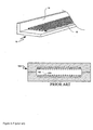
- thermosyphons From GB-2151769 it is known to manufacture extruded heat sinks having internal cavities acting as thermosyphons (see figure 8). The cavities are elongated without any internal structure. The cooling efficiency of this kind of thermosyphon is limited.
- thermosyphon concept for cooling of PCB In "Thermosyphon concept for cooling of PCB", Rahmatollah, K et al, 8 th THERMINIC Workshop, 1-4 October 2002, Madrid, a concept of cooling PCB:s by using an aluminium sheet having a milled channel system. The thermosyphon is attached to the heat sink, and thus not integrated with it as in the present invention.
- thermosyphon of the present invention it is an object of the present invention to provide a method suitable for mass production of the thermosyphon of the present invention.
- thermosyphon with a more efficient heat transfer than could be obtained by the thermosyphons of the prior art.
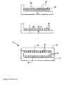
- FIG 1a the principle of the integrated thermosyphon according to a first embodiment is shown.
- a working fluid is heated in the evaporator section whereby the working fluid evaporates and the vapour formed travels in the direction of the arrows, and is condensed back to liquid in the condenser section.
- Figure 1b is a cross section taken across the line B-B.
- the evaporator fins (4) are integrally produced with the lid (3) by extruding the lid and cutting the extruded profile in desired lengths, whereafter the fins in areas outside the evaporator section are removed by milling.
- the condenser section shown in figure 1c as a cross section taken across the line A-A in figure 1a.
- thermosyphon further comprises extruded heat dissipating fins (1) extending from the base.
- Other solutions resulting in the same or similar s may be obtained by extruding part of the condenser as a part of the lid, or manufacturing the evaporator section as a part of the heat sink base.
- the fins of the evaporator and/or condenser section at least partially produced by extrusion, form an internal structure with an extended surface area, providing a more efficient heat transfer between the working fluid and the thermosyphon.
- thermosyphon having a base (B) and a plurality of condenser fins (A) extending vertically from the base.
- a lid comprising a number of evaporator fins (E) with a separating distance smaller than the distance between the condenser fins extending vertically from the lid is placed over the channel structure (D) so that a thermosyphon of an expanding channel system is formed.
- a heat dissipating component (F) is attached to the outside of the lid.
- the contact thermal resistance between the lid and the fins is eliminated, which makes the thermosyphon more efficient.
- the heat dissipating fins are integrated in the thermosyphon, which eliminates the contact thermal resistance between the condenser fins and the outer heat dissipating fins.
- Figure 2b shows an alternative embodiment, the reference letters referring to the same components as in figure 2a, where the condenser section and the evaporator section are separated and connected by pipes (D) conducting the evaporated working media from the evaporator to the condenser where it is condensed to a liquid and transferred by gravity back to the evaporator. Lids are placed over the evaporator and condenser sections in a similar way as in the first embodiment.
- joining is preferably done by, but not limited to, friction stir welding.
- This joining technique is described in EP-A-615480.
- a friction welding tool inserted into a joint region to be welded, undergoes a cyclic motion to generate a plastizised material and is typically traversed along the joint region. When the material cools a joint of high quality is produced.
- the present invention provides a new way of efficiently manufacturing an integrated structure, while keeping the heat transfer of the structure high.
- the material selection for the base and lid depends on application requirements for ease of fabrication and service reliability. Aluminum is preferred because of its ease of machinability and lower density compared to other metals, but other materials may also be used.
- a lid is extruded from an aluminium billet so that a plate is formed having fins extending from one side along the centre of the plate.
- the fins extending beyond the area dedicated to the evaporator are removed by milling to form the evaporator section, E, according to figure 2a.
- a base is then extruded to form a plate having heat dissipating fins extending from one side.
- the flat side of the base is machined so that condenser channels, A, are formed in a pattern according to figure 2a as well as a cavity for the evaporator fins to fit into.
- the lid is joined to the base by traversing a friction stir welding tool along the joint (shown as the contour of the thermosyphon in figure 1a).
- thermosyphon When the lid and the base are joined a sealed chamber constituting a thermosyphon is formed inside the chamber.
- the evaporator is filled with liquid.
- the choice of working fluid is based upon the working temperature of the thermosyphon, and may be chosen according to the specific demands in each case.
- the heat source (F) is attached to the lid. Under thermal loading, a part of the liquid in the evaporator transforms to gas and flows up to condenser where the vapour is condensed to liquid and flows back to evaporator via the liquid return channel.
- the evaporator may for example be a part of the base and the condenser a part of the lid. All parts may be extruded including the fins of the condenser and the fins removed from areas used for joining of the parts. In the latter case all of the fins may be produced integrally with either the lid or the heat sink base or as parts of either the lid or the base.
- thermosyphon manufacturing By extruding parts or all of the parts of the thermosyphon manufacturing is simplified and heat transfer improved.
Landscapes
- Engineering & Computer Science (AREA)
- Physics & Mathematics (AREA)
- Thermal Sciences (AREA)
- Mechanical Engineering (AREA)
- General Engineering & Computer Science (AREA)
- Life Sciences & Earth Sciences (AREA)
- Sustainable Development (AREA)
- Cooling Or The Like Of Semiconductors Or Solid State Devices (AREA)
- Cooling Or The Like Of Electrical Apparatus (AREA)
Applications Claiming Priority (2)
| Application Number | Priority Date | Filing Date | Title |
|---|---|---|---|
| SE0301381 | 2003-05-12 | ||
| SE0301381A SE0301381D0 (sv) | 2003-05-12 | 2003-05-12 | Extruded heat sink with integrated thermosyphon |
Publications (2)
| Publication Number | Publication Date |
|---|---|
| EP1477762A2 true EP1477762A2 (de) | 2004-11-17 |
| EP1477762A3 EP1477762A3 (de) | 2006-06-07 |
Family
ID=20291279
Family Applications (1)
| Application Number | Title | Priority Date | Filing Date |
|---|---|---|---|
| EP04076228A Withdrawn EP1477762A3 (de) | 2003-05-12 | 2004-04-26 | Thermosyphon und Verfahren zu dessen Herstellung |
Country Status (4)
| Country | Link |
|---|---|
| US (1) | US20050056403A1 (de) |
| EP (1) | EP1477762A3 (de) |
| CN (1) | CN1551724B (de) |
| SE (1) | SE0301381D0 (de) |
Cited By (4)
| Publication number | Priority date | Publication date | Assignee | Title |
|---|---|---|---|---|
| EP1923770A1 (de) * | 2006-11-14 | 2008-05-21 | Orra Corporation | Computermodul |
| WO2010026486A3 (en) * | 2008-09-05 | 2010-06-10 | Molex Kiire Co., Ltd. | Heat pipe and electronic device |
| ITBO20120618A1 (it) * | 2012-11-09 | 2014-05-10 | Mecc Al S R L A Socio Unico | Procedimento per la realizzazione di un dissipatore e dissipatore cosi' ottenuto |
| CN108917439A (zh) * | 2018-08-30 | 2018-11-30 | 无锡格林沃科技有限公司 | 新型相变散热器 |
Families Citing this family (28)
| Publication number | Priority date | Publication date | Assignee | Title |
|---|---|---|---|---|
| US6935409B1 (en) * | 1998-06-08 | 2005-08-30 | Thermotek, Inc. | Cooling apparatus having low profile extrusion |
| US7147045B2 (en) | 1998-06-08 | 2006-12-12 | Thermotek, Inc. | Toroidal low-profile extrusion cooling system and method thereof |
| US7305843B2 (en) * | 1999-06-08 | 2007-12-11 | Thermotek, Inc. | Heat pipe connection system and method |
| US7857037B2 (en) | 2001-11-27 | 2010-12-28 | Thermotek, Inc. | Geometrically reoriented low-profile phase plane heat pipes |
| US9113577B2 (en) | 2001-11-27 | 2015-08-18 | Thermotek, Inc. | Method and system for automotive battery cooling |
| US7198096B2 (en) * | 2002-11-26 | 2007-04-03 | Thermotek, Inc. | Stacked low profile cooling system and method for making same |
| US7958935B2 (en) * | 2004-03-31 | 2011-06-14 | Belits Computer Systems, Inc. | Low-profile thermosyphon-based cooling system for computers and other electronic devices |
| CA2561769C (en) * | 2004-03-31 | 2009-12-22 | Belits Computer Systems, Inc. | Low-profile thermosyphon-based cooling system for computers and other electronic devices |
| US7772456B2 (en) * | 2004-06-30 | 2010-08-10 | Kimberly-Clark Worldwide, Inc. | Stretchable absorbent composite with low superaborbent shake-out |
| TWI262285B (en) * | 2005-06-03 | 2006-09-21 | Foxconn Tech Co Ltd | Loop-type heat exchange apparatus |
| JP2007003164A (ja) * | 2005-06-27 | 2007-01-11 | Nakamura Mfg Co Ltd | 平板状ヒートパイプまたはベーパーチャンバー、および、その形成方法 |
| US7900692B2 (en) * | 2005-10-28 | 2011-03-08 | Nakamura Seisakusho Kabushikigaisha | Component package having heat exchanger |
| CN101155497A (zh) * | 2006-09-29 | 2008-04-02 | 诺亚公司 | 相变散热装置与方法 |
| EP2246653B1 (de) * | 2009-04-28 | 2012-04-18 | ABB Research Ltd. | Wärmerohr mit gewundenem Rohr |
| EP2246654B1 (de) * | 2009-04-29 | 2013-12-11 | ABB Research Ltd. | Mehrreihiger Thermosyphon-Wärmetauscher |
| US9091489B2 (en) | 2010-05-14 | 2015-07-28 | Paragon Space Development Corporation | Radiator systems |
| CN102338581B (zh) * | 2010-07-23 | 2013-10-30 | 奇鋐科技股份有限公司 | 热虹吸板结构 |
| CN102338583B (zh) * | 2010-07-23 | 2014-05-07 | 奇鋐科技股份有限公司 | 一种压力差驱动热板 |
| WO2012115214A1 (ja) * | 2011-02-22 | 2012-08-30 | 日本電気株式会社 | 冷却装置及びその製造方法 |
| WO2013169774A2 (en) | 2012-05-07 | 2013-11-14 | Phononic Devices, Inc. | Thermoelectric heat exchanger component including protective heat spreading lid and optimal thermal interface resistance |
| US20130291555A1 (en) | 2012-05-07 | 2013-11-07 | Phononic Devices, Inc. | Thermoelectric refrigeration system control scheme for high efficiency performance |
| JP5754431B2 (ja) * | 2012-10-10 | 2015-07-29 | 日本軽金属株式会社 | ヒートシンクの製造方法及び伝熱板の製造方法 |
| CN103813695B (zh) * | 2012-11-13 | 2016-08-17 | 台达电子工业股份有限公司 | 虹吸式散热装置 |
| US9593871B2 (en) | 2014-07-21 | 2017-03-14 | Phononic Devices, Inc. | Systems and methods for operating a thermoelectric module to increase efficiency |
| US10458683B2 (en) | 2014-07-21 | 2019-10-29 | Phononic, Inc. | Systems and methods for mitigating heat rejection limitations of a thermoelectric module |
| JP6679573B2 (ja) | 2014-08-28 | 2020-04-15 | アアヴィッド・サーマロイ・エルエルシー | 一体構成要素を備えたサーモサイホン |
| CN109900146A (zh) * | 2019-03-28 | 2019-06-18 | 南昌大学 | 一种带有热虹吸回路的双锥度微通道散热器 |
| CN118670176A (zh) * | 2023-03-16 | 2024-09-20 | 台达电子工业股份有限公司 | 虹吸式散热器 |
Citations (3)
| Publication number | Priority date | Publication date | Assignee | Title |
|---|---|---|---|---|
| GB2151769A (en) | 1983-12-21 | 1985-07-24 | Marconi Electronic Devices | Heat sink arrangement |
| US6216343B1 (en) | 1999-09-02 | 2001-04-17 | The United States Of America As Represented By The Secretary Of The Air Force | Method of making micro channel heat pipe having corrugated fin elements |
| US6418017B1 (en) | 2000-03-30 | 2002-07-09 | Hewlett-Packard Company | Heat dissipating chassis member |
Family Cites Families (27)
| Publication number | Priority date | Publication date | Assignee | Title |
|---|---|---|---|---|
| DE3504992A1 (de) * | 1985-02-14 | 1986-08-14 | Brown, Boveri & Cie Ag, 6800 Mannheim | Leistungshalbleitermodul mit integriertem waermerohr |
| DE3825981A1 (de) * | 1988-07-27 | 1990-02-15 | Licentia Gmbh | Isothermisierter kuehlkoerper |
| US5308920A (en) * | 1992-07-31 | 1994-05-03 | Itoh Research & Development Laboratory Co., Ltd. | Heat radiating device |
| US5303768A (en) * | 1993-02-17 | 1994-04-19 | Grumman Aerospace Corporation | Capillary pump evaporator |
| US5394936A (en) * | 1993-03-12 | 1995-03-07 | Intel Corporation | High efficiency heat removal system for electric devices and the like |
| JPH06266474A (ja) * | 1993-03-17 | 1994-09-22 | Hitachi Ltd | 電子機器装置及びラップトップ型電子機器装置 |
| JP3385482B2 (ja) * | 1993-11-15 | 2003-03-10 | 株式会社日立製作所 | 電子機器 |
| US5529115A (en) * | 1994-07-14 | 1996-06-25 | At&T Global Information Solutions Company | Integrated circuit cooling device having internal cooling conduit |
| TW307837B (de) * | 1995-05-30 | 1997-06-11 | Fujikura Kk | |
| JP3634028B2 (ja) * | 1995-09-08 | 2005-03-30 | 住友精密工業株式会社 | 半導体素子冷却装置 |
| US5725049A (en) * | 1995-10-31 | 1998-03-10 | The United States Of America As Represented By The Administrator Of The National Aeronautics And Space Administration | Capillary pumped loop body heat exchanger |
| JPH10154781A (ja) * | 1996-07-19 | 1998-06-09 | Denso Corp | 沸騰冷却装置 |
| DE19805930A1 (de) * | 1997-02-13 | 1998-08-20 | Furukawa Electric Co Ltd | Kühlvorrichtung |
| US6227287B1 (en) * | 1998-05-25 | 2001-05-08 | Denso Corporation | Cooling apparatus by boiling and cooling refrigerant |
| EP1035398B1 (de) * | 1999-03-05 | 2004-01-14 | Denso Corporation | Kühlungsvorrichtung mit siedendem und kondensierendem Kühlmittel |
| US6360814B1 (en) * | 1999-08-31 | 2002-03-26 | Denso Corporation | Cooling device boiling and condensing refrigerant |
| KR100338810B1 (ko) * | 1999-11-08 | 2002-05-31 | 윤종용 | 냉각장치 |
| DE10006215A1 (de) * | 2000-02-11 | 2001-08-16 | Abb Semiconductors Ag Baden | Kühlvorrichtung für ein Hochleistungs-Halbleitermodul |
| JP2002141449A (ja) * | 2000-10-31 | 2002-05-17 | Denso Corp | 沸騰冷却器 |
| US6483705B2 (en) * | 2001-03-19 | 2002-11-19 | Harris Corporation | Electronic module including a cooling substrate and related methods |
| US6609560B2 (en) * | 2001-04-28 | 2003-08-26 | Samsung Electronics Co., Ltd. | Flat evaporator |
| JP2003035470A (ja) * | 2001-05-15 | 2003-02-07 | Samsung Electronics Co Ltd | 微細ウィック構造を有するcpl冷却装置の蒸発器 |
| JP3946018B2 (ja) * | 2001-09-18 | 2007-07-18 | 株式会社日立製作所 | 液冷却式回路装置 |
| KR100438825B1 (ko) * | 2001-10-29 | 2004-07-05 | 삼성전자주식회사 | 단열 수단을 구비하는 열 전달 장치 |
| JP4032954B2 (ja) * | 2002-07-05 | 2008-01-16 | ソニー株式会社 | 冷却装置、電子機器装置、音響装置及び冷却装置の製造方法 |
| JP2004037039A (ja) * | 2002-07-05 | 2004-02-05 | Sony Corp | 冷却装置、電子機器装置、表示装置及び冷却装置の製造方法 |
| JP2004077051A (ja) * | 2002-08-20 | 2004-03-11 | Sony Corp | 熱輸送装置およびその製造方法 |
-
2003
- 2003-05-12 SE SE0301381A patent/SE0301381D0/xx unknown
-
2004
- 2004-04-26 EP EP04076228A patent/EP1477762A3/de not_active Withdrawn
- 2004-04-28 US US10/833,324 patent/US20050056403A1/en not_active Abandoned
- 2004-05-12 CN CN2004100431418A patent/CN1551724B/zh not_active Expired - Fee Related
Patent Citations (3)
| Publication number | Priority date | Publication date | Assignee | Title |
|---|---|---|---|---|
| GB2151769A (en) | 1983-12-21 | 1985-07-24 | Marconi Electronic Devices | Heat sink arrangement |
| US6216343B1 (en) | 1999-09-02 | 2001-04-17 | The United States Of America As Represented By The Secretary Of The Air Force | Method of making micro channel heat pipe having corrugated fin elements |
| US6418017B1 (en) | 2000-03-30 | 2002-07-09 | Hewlett-Packard Company | Heat dissipating chassis member |
Cited By (4)
| Publication number | Priority date | Publication date | Assignee | Title |
|---|---|---|---|---|
| EP1923770A1 (de) * | 2006-11-14 | 2008-05-21 | Orra Corporation | Computermodul |
| WO2010026486A3 (en) * | 2008-09-05 | 2010-06-10 | Molex Kiire Co., Ltd. | Heat pipe and electronic device |
| ITBO20120618A1 (it) * | 2012-11-09 | 2014-05-10 | Mecc Al S R L A Socio Unico | Procedimento per la realizzazione di un dissipatore e dissipatore cosi' ottenuto |
| CN108917439A (zh) * | 2018-08-30 | 2018-11-30 | 无锡格林沃科技有限公司 | 新型相变散热器 |
Also Published As
| Publication number | Publication date |
|---|---|
| EP1477762A3 (de) | 2006-06-07 |
| CN1551724B (zh) | 2010-08-04 |
| CN1551724A (zh) | 2004-12-01 |
| SE0301381D0 (sv) | 2003-05-12 |
| US20050056403A1 (en) | 2005-03-17 |
Similar Documents
| Publication | Publication Date | Title |
|---|---|---|
| EP1477762A2 (de) | Thermosyphon und Verfahren zu dessen Herstellung | |
| RU2247912C2 (ru) | Микрохолодильное устройство | |
| US7106589B2 (en) | Heat sink, assembly, and method of making | |
| JP3936308B2 (ja) | フィン一体型ヒートシンクおよびその製造方法 | |
| EP3174093B1 (de) | Gekühlte leistungselektronikanordnung | |
| US20090308571A1 (en) | Heat transfer assembly and methods therefor | |
| US6749013B2 (en) | Heat sink | |
| WO2002081996A2 (en) | Orientation-independent thermosyphon heat spreader | |
| JP2004523911A (ja) | 熱放散デバイス | |
| JP2005114341A (ja) | ヒートパイプを備えたヒートシンクおよびその製造方法 | |
| US7843693B2 (en) | Method and system for removing heat | |
| JP2004518269A (ja) | 冷却装置及びその製造プロセス | |
| CN111818756B (zh) | 带有集成的两相散热器的热交换器 | |
| US20050135061A1 (en) | Heat sink, assembly, and method of making | |
| JP2003322483A (ja) | 板型ヒートパイプおよびその製造方法 | |
| JP2001156229A (ja) | ヒートシンク及びその製造方法 | |
| JPH10288481A (ja) | 板型ヒートパイプとそれを用いた冷却構造 | |
| JPH04225791A (ja) | ヒートパイプ式放熱器およびその製造方法 | |
| JP4267977B2 (ja) | 冷却モジュール | |
| JP7651699B2 (ja) | 熱デバイス冷却用ヒートシンク | |
| JPH04198690A (ja) | ヒートパイプとその製造方法 | |
| CN222750737U (zh) | 传热系统 | |
| CN216624252U (zh) | 一种密封器件的散热装置 | |
| WO2023276940A1 (ja) | 熱デバイス冷却用ヒートシンク | |
| WO2023276939A1 (ja) | 熱デバイス用ヒートシンク |
Legal Events
| Date | Code | Title | Description |
|---|---|---|---|
| PUAI | Public reference made under article 153(3) epc to a published international application that has entered the european phase |
Free format text: ORIGINAL CODE: 0009012 |
|
| AK | Designated contracting states |
Kind code of ref document: A2 Designated state(s): AT BE BG CH CY CZ DE DK EE ES FI FR GB GR HU IE IT LI LU MC NL PL PT RO SE SI SK TR |
|
| AX | Request for extension of the european patent |
Extension state: AL HR LT LV MK |
|
| 17P | Request for examination filed |
Effective date: 20050510 |
|
| PUAL | Search report despatched |
Free format text: ORIGINAL CODE: 0009013 |
|
| AK | Designated contracting states |
Kind code of ref document: A3 Designated state(s): AT BE BG CH CY CZ DE DK EE ES FI FR GB GR HU IE IT LI LU MC NL PL PT RO SE SI SK TR |
|
| AX | Request for extension of the european patent |
Extension state: AL HR LT LV MK |
|
| RIC1 | Information provided on ipc code assigned before grant |
Ipc: F28D 15/02 20060101ALI20060503BHEP Ipc: H01L 23/427 20060101ALI20060503BHEP Ipc: F28D 15/04 20060101AFI20040915BHEP |
|
| AKX | Designation fees paid |
Designated state(s): AT BE BG CH CY CZ DE DK EE ES FI FR GB GR HU IE IT LI LU MC NL PL PT RO SE SI SK TR |
|
| R17P | Request for examination filed (corrected) |
Effective date: 20050419 |
|
| R17P | Request for examination filed (corrected) |
Effective date: 20050419 |
|
| R17P | Request for examination filed (corrected) |
Effective date: 20050419 |
|
| R17P | Request for examination filed (corrected) |
Effective date: 20050419 |
|
| 17Q | First examination report despatched |
Effective date: 20080708 |
|
| STAA | Information on the status of an ep patent application or granted ep patent |
Free format text: STATUS: THE APPLICATION IS DEEMED TO BE WITHDRAWN |
|
| 18D | Application deemed to be withdrawn |
Effective date: 20131101 |