EP1477794B1 - Inspektionsvorrichtung für Flaschen - Google Patents
Inspektionsvorrichtung für Flaschen Download PDFInfo
- Publication number
- EP1477794B1 EP1477794B1 EP04008175A EP04008175A EP1477794B1 EP 1477794 B1 EP1477794 B1 EP 1477794B1 EP 04008175 A EP04008175 A EP 04008175A EP 04008175 A EP04008175 A EP 04008175A EP 1477794 B1 EP1477794 B1 EP 1477794B1
- Authority
- EP
- European Patent Office
- Prior art keywords
- bottle
- light
- bottles
- illumination
- illumination device
- Prior art date
- Legal status (The legal status is an assumption and is not a legal conclusion. Google has not performed a legal analysis and makes no representation as to the accuracy of the status listed.)
- Expired - Lifetime
Links
Images

Classifications
-
- G—PHYSICS
- G01—MEASURING; TESTING
- G01N—INVESTIGATING OR ANALYSING MATERIALS BY DETERMINING THEIR CHEMICAL OR PHYSICAL PROPERTIES
- G01N21/00—Investigating or analysing materials by the use of optical means, i.e. using sub-millimetre waves, infrared, visible or ultraviolet light
- G01N21/84—Systems specially adapted for particular applications
- G01N21/88—Investigating the presence of flaws or contamination
- G01N21/90—Investigating the presence of flaws or contamination in a container or its contents
Definitions
- the invention relates to an inspection device for bottles or the like. Vessels according to the preamble of claim 1.
- DE 199 04 732 A1 and DE 195 38 013 A1 disclose inspection devices for contour detection or dimension determination of bottles.
- image acquisition and illumination take place from opposite sides of a bottle to be tested, ie the inspection process takes place in the case of backlight, wherein transparent bottles are transilluminated (transmitted light method).
- combined inspection devices which can perform both a label inspection and contour recognition.
- incident light illumination for label or print image recognition as well as transmitted light illumination for contour control
- two illumination devices radiating from different directions are used.
- disadvantageously the coordination of the individual lighting intensity and duration is problematic. Even at the initial optimum setting, it is not possible to reliably prevent the setting values from divergence with increasing age or temperature of the light sources.
- EP-A-0 657 732 describes a device for the top view of the mouth region of a container, in which the light of an annular light source arranged above the container is directed obliquely via optical luminous surfaces onto the container mouth and the region of the lateral surface adjoining thereto. As a result, both transmitted light and incident light is generated.
- the image-side beam path extends through the central opening of the light source vertically upwards.
- US 2001/048524 A1 further describes a device for inspecting a bottle closure with the aid of reflected light, the reflections of which are imaged on the surface to be examined by a camera arranged above the bottle.
- the light source consists of an annular collection of LEDs, whose light is directed obliquely on each individually adjustable mirror elements on the bottle closure.
- the object of the invention is to provide an inspection device with improved and simplified illumination.
- the illumination device is arranged above a bottle to be examined and irradiates it mainly from the outside predominantly along the bottle vertical axis, in particular at an acute angle obliquely from above.
- a part of the light originating from the illumination device can be deflected approximately transversely to the bottle axis by the said optical means and is directed, at least for the most part, radially extending onto the lateral surface of the bottle.
- the optical means are as or reflecting surface elements formed, for example as flat plates with a light surface. These include white plastic plates or the like. Usable. These optical means can be arranged laterally next to a transport device continuously transporting the bottles in a single-track row, wherein an image recording device images the lateral surface of a bottle to be examined approximately transversely to the bottle axis on the opposite side of the transport device.
- optical means in particular mirrors, can be arranged to produce a plurality of imaging beam paths passing through the lateral surface of a bottle from circumferentially different directions.
- the aforementioned light-diffusing or light-reflecting surface elements are preferably positioned perpendicular to the optical axis of the respectively associated imaging beam path.
- optical fibers, prisms, mirrors or mirrors combined with lenses are also conceivable. They can also be designed and arranged so that a bottle to be checked can be illuminated simultaneously from several directions.
- the surface elements for adjusting the illumination intensity are relatively, in particular radially, adjustable to a bottle to be examined and the light source arranged above, preferably along the optical axis of an associated imaging beam path.
- a distance adjustment of the surface elements with respect to a bottle to be examined is with relatively little effort vorappelbar relatively quickly.
- the illumination device arranged above the transport device has a light exit surface that is larger than the vertical projection surface of a bottle to be examined.
- the outer surface of a bottle can be reliably exposed from the outside to light at least approximately over its entire height, in particular in conjunction with lenses arranged between the illumination device and the bottle, e.g. Fresnel lenses.
- Both light reflected from the outer surface and light falling directly from the lamp onto the light-diffusing or light-reflecting surface elements is predominantly deflected transversely to the axis of the bottle. In this way, the outer contour of a bottle before the bright background formed by the surface elements can be clearly recognized and evaluated.
- the inspection device 1 is arranged on a bottle 2 in a single-track row with at least small intermediate distances transporting conveyor 3, the bottles to be examined 2 upright by means of a conveyed by friction on its bottom surface attacking hinge belt continuously.
- the inspection device 1 has an image pickup device 5, for example a CCD camera, accommodated in a housing 11 located laterally next to the feed dog 3.
- a transporter with intermediate spacing cross-arm 12 is fixed to the underside of a centrally above the conveyor 3 aligned lighting device 4 is mounted.
- light-reflecting or-scattering surface elements 6 are suspended. These surface elements 6 are located on the side opposite the image pickup device 5 side of the conveyor 3 radially adjacent to the lateral surface of a bottle to be examined 2 and extending parallel to the bottle axis 2 'extending over the entire height.
- a light sensor 13 is arranged on the boom 12 also hanging a light sensor 13 is arranged, the optical axis 13 'crosses the conveyor track of the bottles approximately at right angles.
- the light scanner opposite a reflector 14 is disposed in the housing 11. It is located immediately behind a protective pane 15 fitted in a housing opening on the side facing the feed dog 3.
- the two surface elements 6 are each positioned at an angle approximately at 40 ° to 45 ° to the conveying direction of the transporter 3 at an angle to each other, wherein the radial distance of the flat, perpendicularly downwardly depending surface elements 6 to one to be tested Bottle 2 and the concentrically arranged above lighting device 4 is adjustable.
- the already mentioned lighting device 4 has as a light source a plurality of densely packed on a flat, horizontally arranged support disc arranged LEDs 9 with an underlying Fresnel lens 10, which defines a circular light exit surface of the illumination device 4, whose diameter D is greater than the diameter of a bottle with its axis. 2 'concentrically below bottle 2 is.
- the alignment of the two outer mirrors 7a, 7b is made such that the beam paths intersect over the feed dog 3 in the region of the bottle axis 2 'of a bottle 2 concentrically under the circular light exit surface of the lighting device 4 and extend at right angles to the light-scattering surface of the surface elements 6.
- a deflection mirror 7 " which is common to both beam paths and is arranged in the region in front of the vertically downward-facing, height-adjustable CCD camera 5, permits a small overall depth of the housing 11.
- a bottle 2 to be inspected is fed to the inspection device 1 in the direction of the arrow and passes through a light beam 13 'emitted by the light scanner 13 at right angles to the conveying direction in a horizontal plane.
- the light sensor 13 then sends a signal to a controller, not shown, which simultaneously controls the illumination device 4 and the CCD camera 5.
- the light impinging on the side of the bottle 2 facing the CCD camera 5 from above is predominantly reflected, largely radially outwards in the direction of the protective screen 15 in the housing 11.
- Both via the mirrors 7a, 7a ', 7 " the path of the beam path 8a as well as the mirror 7b, 7b ', 7 "on the path of the beam path 8b incident light arriving at the CCD camera 5 generates in each case an identically sized image of the side wall of the bottle 2, from which, for example, a burn-in label possibly present on the bottle can be recognized.
- the light falling from above onto the side of the bottle 2 facing away from the CCD camera 5 is for the most part reflected laterally in the direction of the surface elements 6.
- the surface elements 6 also directly from the one emitting cone having LEDs 9 coming light hits. Both portions are scattered or reflected by the surface elements 6 and thereby deflected to a large extent transversely to the axis 2 'of the bottle 2.
- transparent bottles they penetrate mainly to the central portion, i. Near the center of the area of the lateral surface falling light components, the bottle walls, while the incident on the more curved edge regions light is predominantly reflected. A part of this reflected light entering the beam paths 8a, 8b can amplify the incident light illumination mentioned above.
- the light which passes through the bottle walls and enters the beam paths 8a, 8b likewise reaches the CCD camera 5 and forms the bottle sidewall in a well contoured contour in front of the surface elements 6 which supply a light image background. In this way, the contour and any existing labels are perfectly imaged.
- the image evaluation is carried out by an integrated into the CCD camera 5 evaluation in conjunction with stored image processing software.
- signals can be generated which, for example, can be used downstream of the inspection device 1 downstream, sorting and / or discharge devices, not shown, in order to sort bottles with different contours and / or with such Separate labels, in particular burn-in labels, from label-free bottles.
Landscapes
- Physics & Mathematics (AREA)
- Health & Medical Sciences (AREA)
- Life Sciences & Earth Sciences (AREA)
- Chemical & Material Sciences (AREA)
- Analytical Chemistry (AREA)
- Biochemistry (AREA)
- General Health & Medical Sciences (AREA)
- General Physics & Mathematics (AREA)
- Immunology (AREA)
- Pathology (AREA)
- Investigating Materials By The Use Of Optical Means Adapted For Particular Applications (AREA)
- Image Input (AREA)
Description
- Die Erfindung betrifft eine Inspektionsvorrichtung für Flaschen oder dgl. Gefäße gemäß dem Oberbegriff des Anspruchs 1.
- Aus
US 4 509 081 ist eine Inspektionsvorrichtung zur Etikettenkontrolle an Flaschen bekannt. Die zu überprüfenden Flaschen werden in einer einspurigen Reihe an einer Beleuchtungseinrichtung vorbeigeführt und von der Seite quer zu ihrer Hochachse mit Licht beaufschlagt. Die zur Abbildung der Flaschen vorgesehene Kamera betrachtet die zu untersuchenden Flaschen von der gleichen Seite, von der auch die Beleuchtung erfolgt; die Inspektion erfolgt somit im Auflichtverfahren. -
DE 199 04 732 A1 undDE 195 38 013 A1 offenbaren Inspektionsvorrichtungen zur Konturerkennung bzw. Dimensionsbestimmung von Flaschen. Hier erfolgen Bildaufnahme und Beleuchtung von gegenüberliegenden Seiten einer zu prüfenden Flasche, d.h. der Inspektionsvorgang findet bei Gegenlicht statt, wobei transparente Flaschen durchleuchtet werden (Durchlichtverfahren). - Desweiteren sind kombinierte Inspektionsvorrichtungen bekannt, die sowohl eine Etikettenkontrolle als auch Konturerkennung durchführen können. Für die Auflichtbeleuchtung zur Etiketten- bzw. Druckbilderkennung sowie die Durchlichtbeleuchtung für die Konturkontrolle werden zwei aus verschiedenen Richtungen strahlende Beleuchtungseinrichtungen eingesetzt. Bei der Verwendung von zwei Lichtquellen hat sich gezeigt, dass nachteiligerweise die Abstimmung der Einzelbeleuchtungsstärke und -dauer problematisch ist. Selbst bei anfänglich optimaler Einstellung ist ein Auseinandertriften der Einstellwerte mit zunehmendem Alter oder Temperatur der Lichtquellen nicht zuverlässig vermeidbar.
-
EP-A-0 657 732 beschreibt eine Vorrichtung zur Aufsicht-Darstellung des Mündungsbereichs eines Behälters, bei der das Licht einer ringförmigen, über dem Behälter angeordneten Lichtquelle über optische Leuchtflächen schräg auf die Behältermündung und den daran angrenzenden Bereich der Mantelfläche gerichtet wird. Dadurch wird sowohl Durchlicht als auch Auflicht erzeugt. Der bildseitige Strahlengang verläuft durch die zentrale Öffnung der Lichtquelle senkrecht nach oben. -
US 2001/048524 A1 beschreibt ferner eine Vorrichtung zur Inspektion eines Flaschenverschlusses mit Hilfe von Auflicht, dessen Reflexionen an der zu untersuchenden Oberfläche durch eine über der Flasche angeordnete Kamera abgebildet werden. Die Lichtquelle besteht aus einer ringförmigen Ansammlung von Leuchtdioden, deren Licht schräg über jeweils einzeln verstellbare Spiegelelemente auf den Flaschenverschluss gerichtet wird. - Davon ausgehend liegt der Erfindung die Aufgabe zu Grunde, eine Inspektionsvorrichtung mit verbesserter und vereinfachter Beleuchtung anzugeben.
- Gelöst wird diese Aufgabe durch die kennzeichnenden Merkmale des Anspruchs 1.
- Durch die erfindungsgemäße Maßnahme, die äußere Mantelfläche einer zu untersuchenden Flasche von nur noch einer einzigen Beleuchtungseinrichtung in Verbindung mit optischen Mitteln sowohl mit Durchlicht als auch Auflicht zu beaufschlagen, ist die Abstimmung der Beleuchtungsintensitäten aus den verschiedenen Richtungen auf Grund der nur einen für beide Aufgaben gemeinsamen Lichtquelle leichter zu bewerkstelligen und bleibt während der gesamten Betriebsdauer im gleichen Verhältnis.
- Die Beleuchtungseinrichtung ist oberhalb einer zu untersuchenden Flasche angeordnet und bestrahlt diese hauptsächlich von außen überwiegend längs zur Flaschenhochachse, insbesondere unter einem spitzen Winkel schräg von oben.
- Ein Teil des von der Beleuchtungseinrichtung stammenden Lichts ist durch die genannten optischen Mittel annähernd quer zur Flaschenachse umlenkbar und wird zumindest größtenteils radial verlaufend auf die Mantelfläche der Flasche gerichtet. Die optischen Mittel sind als oder -reflektierende Flächenelemente ausgebildet, z.B. als ebene Platten mit heller Oberfläche. Dazu sind u.a. weiße Kunststoffplatten oder dgl. verwendbar. Diese optischen Mittel können seitlich neben einer die Flaschen kontinuierlich in einer einspurigen Reihe transportierenden Transporteinrichtung angeordnet sein, wobei auf der gegenüberliegenden Seite der Transporteinrichtung eine Bildaufnahmeeinrichtung die Mantelfläche einer zu untersuchenden Flasche annähernd quer zur Flaschenachse abbildet.
- Zwischen der Bildaufnahmeeinrichtung und einer zuuntersuchenden Flasche können optische Mittel, insbesondere Spiegel, zur Erzeugung mehrerer die Mantelfläche einer Flasche aus umfänglich verschiedenen Richtungen durchsetzenden Abbildungsstrahlengängen angeordnet sein.
- In Verlängerung der Abbildungsstrahlengänge befinden sich die vorhergehend genannten lichtstreuenden oder lichtreflektierenden Flächenelemente. Sie sind bevorzugt senkrecht zur optischen Achse des jeweils zugeordneten Abbildungsstrahlengangs positioniert.
- Als optische Mittel sind alternativ auch Lichtleiter, Prismen, mit Linsen kombinierte Spiegel oder Teilerspiegel denkbar. Sie können ebenfalls so ausgebildet und angeordnet sein, dass eine zu überprüfende Flasche aus mehreren Richtungen gleichzeitig beleuchtbar ist.
- Gemäß einer vorteilhaften Weiterbildung sind die Flächenelemente zur Einstellung der Beleuchtungsintensität relativ, insbesondere radial, zu einer zu untersuchenden Flasche und der darüber angeordneten Lichtquelle einstellbar, bevorzugt längs zur optischen Achse eines zugeordneten Abbildungsstrahlengangs. Eine Abstandsverstellung der Flächenelemente bezüglich einer zu untersuchenden Flasche ist mit nur sehr geringem Aufwand verhältnismäßig schnell vornehmbar.
- Die über der Transporteinrichtung angeordnete Beleuchtungseinrichtung besitzt eine Lichtausstrittsfläche, die größer als die senkrechte Projektionsfläche einer zu untersuchenden Flasche ist. Damit kann die Mantelfläche einer Flasche wenigstens annähernd über ihre gesamte Höhe zuverlässig von außen mit Licht beaufschlagt werden, insbesondere in Verbindung mit zwischen der Beleuchtungseinrichtung und der Flasche angeordneten Linsen, z.B. Fresnellinsen. Sowohl von der Mantelfläche nach außen reflektiertes Licht als auch direkt von der Lampe auf die lichtstreuenden oder lichtreflektierenden Flächenelemente fallendes Licht wird überwiegend quer zur Flaschenachse umgelenkt. Auf diese Weise ist die äußere Kontur einer Flasche vor dem durch die Flächenelemente gebildeten hellen Hintergrund einwandfrei erkenn- und auswertbar.
- Weitere vorteilhafte Ausgestaltungen der. Erfindung sind Gegenstand der verbleibenden Unteransprüche.
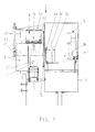
- Nachfolgend wird ein bevorzugtes Ausführungsbeispiel anhand der Figuren erläutert. Es zeigt:
- Fig. 1
- eine Draufsicht auf eine Inspektionsvorrichtung und
- Fig. 2
- eine Ansicht der Inspektionsvorrichtung entlang der Linie A-A in
Fig. 1 in Transportrichtung der Flaschen betrachtet. - Die Inspektionsvorrichtung 1 ist an einem Flaschen 2 in einer einspurigen Reihe mit zumindest geringen Zwischenabständen transportierenden Transporteur 3 angeordnet, der die zu untersuchenden Flaschen 2 aufrechtstehend mittels einer reibschlüssig an ihrer Bodenfläche angreifenden Scharnierbandkette kontinuierlich befördert. Die Inspektionsvorrichtung 1 weist eine in einem seitlich neben dem Transporteur 3 stehenden Gehäuse 11 untergebrachte Bildaufnahmeeinrichtung 5, z.B. CCD-Kamera auf.
- An der zum Transporteur 3 weisenden Seite des Gehäuses 11 ist ein den Transporteur mit Zwischenabstand übergreifender Ausleger 12 befestigt, an dessen Unterseite eine mittig über dem Transporteur 3 ausgerichtete Beleuchtungseinrichtung 4 angebracht ist. An dem selben Ausleger 12 sind lichtreflektierende bzw. -streuende Flächenelemente 6 hängend gelagert. Diese Flächenelemente 6 befinden sich auf der der Bildaufnahmeeinrichtung 5 gegenüberliegenden Seite des Transporteurs 3 radial neben der Mantelfläche einer zu untersuchenden Flasche 2 und erstrecken sich parallel zur Flaschenachse 2' verlaufend über deren gesamte Höhe.
- Außerdem ist an dem Ausleger 12 ebenfalls hängend ein Lichttaster 13 angeordnet, dessen optische Achse 13' die Förderbahn der Flaschen annähernd rechtwinklig kreuzt. Dem Lichttaster gegenüberliegend ist im Gehäuse 11 ein Reflektor 14 angeordnet. Er befindet sich unmittelbar hinter einer in eine Gehäuseöffnung an der zum Transporteur 3 weisenden Seite eingepasste Schutzscheibe 15.
- Insbesondere aus der
Figur 1 ist gut zu erkennen, dass die beiden Flächenelemente 6 jeweils mit einem in etwa 40° bis 45° betragenden Winkel zur Förderrichtung des Transporteurs 3 schräg zueinander weisend positioniert sind, wobei der radiale Abstand der ebenen, lotrecht nach unten hängenden Flächenelemente 6 zu einer zu prüfenden Flasche 2 bzw. der darüber konzentrisch angeordneten Beleuchtungseinrichtung 4 verstellbar ist. Hierzu sind die die Flächenelemente 6 haltenden Stangen 16 mit schräg zur Förderrichtung im Ausleger 12 eingeformte Schlitze 17 durchgreifenden Klemmschrauben befestigt. - Zwischen den beiden Flächenelementen 6 befindet sich ein freier Spalt, durch den der zur Erzeugung von Triggersignalen dienende Lichttaster 13 vorbeilaufende Flaschen 2 vor dem Reflektor 14 erkennen kann.
- Die bereits erwähnte Beleuchtungseinrichtung 4 besitzt als Leuchtmittel eine Vielzahl von dichtgepackt auf einer ebenen, horizontal angeordneten Trägerscheibe angeordnete LEDs 9 mit einer darunter liegenden Fresnellinse 10, die eine kreisrunde Lichtaustrittsfläche der Beleuchtungseinrichtung 4 definiert, deren Durchmesser D größer als der Flaschendurchmesser einer mit ihrer Achse 2' konzentrisch darunterstehenden Flasche 2 ist.
- Ferner befinden sich im Gehäuse 11 im Bereich zwischen einer zu überprüfenden Flasche 2 und der Bildaufnahmeeinrichtung 5 mehrere auf einer horizontalen Stützplatte vertikal stehende, ebene Umlenkspiegel 7a, 7b, 7a', 7b', die zwei umfänglich versetzt auf die Mantelfläche einer Flasche 2 treffende, gleich lange Strahlengänge 8a,8b zur seitlichen Abbildung der Flaschenmantelfläche über deren gesamte Höhe erzeugen.
- Von den beiden Strahlengängen 8a,8b ist in
Fig.1 jeweils nur die optische Achse angedeutet. Die Ausrichtung der beiden äußeren Spiegel 7a,7b ist so getroffen, dass sich die Strahlengänge über dem Transporteur 3 im Bereich der Flaschenachse 2' einer konzentrisch unter der kreisrunden Lichtaustrittsfläche der Beleuchtungseinrichtung 4 stehenden Flasche 2 schneiden und rechtwinklig zur lichtstreuenden Oberfläche der Flächenelemente 6 verlaufen. - Die erwähnten Schlitze 17 sind zu diesen Strahlengängen 8a,8b fluchtend ausgerichtet. Ein für beide Strahlengänge gemeinsamer, im Bereich vor der vertikal nach unten blickenden, höhenverstellbaren CCD-Kamera 5 angeordneter Umlenkspiegel 7" gestattet eine geringe Bautiefe des Gehäuses 11.
- Nachfolgend wird die Funktionsweise der Inspektionsvorrichtung 1 erläutert:
- Durch den kontinuierlich angetriebenen Transporteur 3 wird eine zu inspizierende, beispielsweise von einer nicht dargestellten Waschmaschine kommende Flasche 2 der Inspektionsvorrichtung 1 in Pfeilrichtung zugeführt und passiert dabei einen vom Lichttaster 13 rechtwinklig zur Förderrichtung in horizontaler Ebene ausgesandten Lichtstrahl 13'. Der Lichttaster 13 sendet daraufhin ein Signal an eine nicht dargestellte Steuerung, die gleichzeitig die Beleuchtungseinrichtung 4 und die CCD-Kamera 5 ansteuert. Die in diesem Augenblick mit ihrer Achse 2'konzentrisch unter der den Durchmesser D aufweisenden kreisrunden Lichtaustrittsfläche der Beleuchtungseinrichtung 4 ausgerichtete Flasche 2 wird von den kurzzeitig aufleuchtenden LEDs 9 von oben bestrahlt, wobei das die Fresnellinse 10 durchdringende Licht mit ansteigendem radialen Abstand vom Zentrum bzw. Mittelpunkt zunehmend zur Achse 2' geneigt auf die gesamte äußere Mantelfläche gerichtet wird.
- Das von oben auf die zur CCD-Kamera 5 weisende Seite der Flasche 2 treffende Licht wird überwiegend reflektiert, und zwar größtenteils radial nach außen in Richtung zur Schutzscheibe 15 im Gehäuse 11. Sowohl das über die Spiegel 7a, 7a', 7'' auf dem Pfad des Strahlengangs 8a als auch das über die Spiegel 7b, 7b', 7" auf dem Pfad des Strahlengangs 8b zur CCD-Kamera 5 gelangende Auflicht erzeugt jeweils ein gleich großes Bild von der Seitenwand der Flasche 2, aus dem beispielsweise ein auf der Flasche eventuell vorhandenes Einbrandetikett erkennbar ist.
- Gleichzeitig wird das von oben auf die von der CCD-Kamera 5 wegweisende Seite der Flasche 2 fallende Licht größtenteils seitlich in Richtung zu den Flächenelementen 6 reflektiert. Außerdem trifft auf die Flächenelemente 6 auch unmittelbar von den einen Abstrahlkegel aufweisenden LEDs 9 kommendes Licht. Beide Anteile werden von den Flächenelementen 6 gestreut bzw. reflektiert und dabei zu einem großen Teil quer zur Achse 2' der Flasche 2 umgelenkt. Bei transparenten Flaschen durchdringen die hauptsächlich auf den Mittelabschnitt, d.h. zentrumsnahen Bereich der Mantelfläche fallenden Lichtanteile die Flaschenwandungen, während das auf die stärker gekrümmten Randbereiche treffende Licht überwiegend reflektiert wird. Ein Teil dieses reflektierten und in die Strahlengänge 8a,8b gelangenden Lichts kann die zuvor genannte Auflichtbeleuchtung verstärken. Das die Flaschenwandungen durchdringende, in die Strahlengänge 8a,8b gelangende Licht erreicht ebenfalls die CCD-Kamera 5 und bildet die Flaschenseitenwand vor den einen hellen Bildhintergrund liefernden Flächenelementen 6 gut umrißkonturiert ab. Auf diese Weise sind die Kontur und ggf. vorhandene Etiketten einwandfrei abbildbar.
- Die Bildauswertung erfolgt durch eine in die CCD-Kamera 5 integrierte Auswertelektronik in Verbindung mit gespeicherter Bildverarbeitungssoftware. Vorgebbaren Kriterien entsprechend können Signale erzeugt werden, die beispielsweise zur Ansteuerung von der Inspektionsvorrichtung 1 stromab nachgeordneten, nicht dargestellten Sortier- und/oder Ausschleuseinrichtungen verwendbar sind, um Flaschen mit unterschiedlicher Kontur zu sortieren und/oder solche mit Etiketten, insbesondere Einbrandetiketten, von etikettenfreien Flaschen zu separieren.
Claims (9)
- Inspektionsvorrichtung(1) für Flaschen(2) oder dgl. Gefäße mit Beleuchtungseinrichtungen(4) für eine Durchlicht- und Auflichtbeleuchtung und wenigstens einer Bildaufnahmeeinrichtung(5) zum Abbilden der Mantelfläche der beleuchteten Flaschen und Auswerten der Abbildungen, insbesondere in Bezug auf die Kontur von Flaschen und/oder Etiketten bzw. Abbildungen auf Flaschen, bei der die Mantelfläche einer zu untersuchenden Flasche(2) von nur einer einzigen Beleuchtungseinrichtung(4) in Verbindung mit optischen Mitteln(6) sowohl mit Durchlicht als auch Auflicht beaufschlagbar ist, und die Beleuchtungseinrichtung(4) oberhalb einer zu untersuchenden Flasche(2) angeordnet ist,
dadurch gekennzeichnet, dass
die Beleuchtungseinrichtung die Flasche überwiegend parallel zu ihrer Flaschenachse(2') von oben beleuchtet,
ein Teil des von der Beleuchtungseinrichtung(4) stammenden Lichts durch die optischen Mittel(6) annähernd quer zur Flaschenachse(2') umlenkbar und auf die Mantelfläche der Flasche(2) richtbar ist,
die optischen Mittel(6) als lichtstreuende oder reflektierende Flächenelemente ausgebildet sind, und
die Lichtaustrittsfläche der Beleuchtungseinrichtung(4) größer als die senkrechte Projektionsfläche einer zu prüfenden Flasche(2) ist. - Vorrichtung nach Anspruch 1,
dadurch gekennzeichnet, dass
die Bildaufnahmeeinrichtung(5) die Mantelfläche der Flasche(2) annähernd quer zur Flaschenachse(2') abbildet. - Vorrichtung nach Anspruch 1 oder 2,
dadurch gekennzeichnet, dass
eine Transporteinrichtung(3) zum insbesondere kontinuierlichen Fördern von Flaschen(2) vorhanden ist, über der die Beleuchtungseinrichtung(4) angeordnet ist. - Vorrichtung nach Anspruch 3,
dadurch gekennzeichnet, dass
die Bildaufnahmeeinrichtung(5) seitlich neben der Transporteinrichtung(3) angeordnet ist. - Vorrichtung nach Anspruch 3 oder 4,
dadurch gekennzeichnet, dass
die optischen Mittel(6) seitlich neben der Transporteinrichtung(3) angeordnet sind, vorzugsweise an der der Bildaufnahmeeinrichtung(5) gegenüberliegenden Seite der Transporteinrichtung. - Vorrichtung nach wenigstens einem der vorhergehenden Ansprüche 1 bis 5,
dadurch gekennzeichnet, dass
zwischen der Bildaufnahmeeinrichtung(5) und einer zu untersuchenden Flasche(2) Mittel(7a,7b,7a',7b'), insbesondere Spiegel, zur Erzeugung mehrerer die Mantelfläche der Flasche(2) aus umfänglich verschiedenen Richtungen durchsetzenden Abbildungsstrahlengängen(8a,8b) angeordnet sind. - Vorrichtung nach Anspruch 1 und 6,
dadurch gekennzeichnet, dass
die Flächenelemente(6) in Verlängerung der Abbildungsstrahlengänge(8a,8b) angeordnet sind, insbesondere senkrecht zur optischen Achse des zugeordneten Abbildungsstrahlengangs. - Vorrichtung nach wenigstens einem der vorhergehenden Ansprüche 1 bis 7,
dadurch gekennzeichnet, dass
die Beleuchtungseinrichtung(4) eine Linse(10) aufweist. - Vorrichtung nach Anspruch 1 und 8,
dadurch gekennzeichnet, dass
das Licht mit steigendem radialen Abstand vom Zentrum der Beleuchtungseinrichtung(4) mit einem zunehmend größeren Winkel zur Flaschenachse(2') geneigt austritt.
Applications Claiming Priority (2)
| Application Number | Priority Date | Filing Date | Title |
|---|---|---|---|
| DE10322459A DE10322459B3 (de) | 2003-05-16 | 2003-05-16 | Inspektionsvorrichtung für Flaschen |
| DE10322459 | 2003-05-16 |
Publications (2)
| Publication Number | Publication Date |
|---|---|
| EP1477794A1 EP1477794A1 (de) | 2004-11-17 |
| EP1477794B1 true EP1477794B1 (de) | 2009-08-05 |
Family
ID=33016443
Family Applications (1)
| Application Number | Title | Priority Date | Filing Date |
|---|---|---|---|
| EP04008175A Expired - Lifetime EP1477794B1 (de) | 2003-05-16 | 2004-04-03 | Inspektionsvorrichtung für Flaschen |
Country Status (4)
| Country | Link |
|---|---|
| EP (1) | EP1477794B1 (de) |
| AT (1) | ATE438846T1 (de) |
| DE (3) | DE10322459B3 (de) |
| ES (1) | ES2328133T3 (de) |
Cited By (1)
| Publication number | Priority date | Publication date | Assignee | Title |
|---|---|---|---|---|
| US11371946B2 (en) | 2018-04-09 | 2022-06-28 | Sacmi Cooperativa Meccanici Imola Societa' Cooperativa | Apparatus and method for optical inspection of objects |
Families Citing this family (16)
| Publication number | Priority date | Publication date | Assignee | Title |
|---|---|---|---|---|
| DE102005017957A1 (de) * | 2005-04-18 | 2006-10-26 | Khs Ag | Inspektionsvorrichtung |
| DE202005020478U1 (de) * | 2005-12-30 | 2007-05-24 | Krones Ag | Vorrichtung zum Inspizieren von Etiketten auf Gefäßen |
| DE102007054657A1 (de) | 2006-11-15 | 2008-07-03 | Loell Industry Solutions Gmbh | Optische Erfassungseinrichtung, insbesondere zur Inspektion von Flaschen, sowie entsprechendes Visualisierungsverfahren |
| DE102007010018A1 (de) | 2007-03-01 | 2008-09-11 | Khs Ag | Verfahren und Inspektionsvorrichtung zur Untersuchung von Behältern |
| DE102007020460B3 (de) | 2007-04-27 | 2009-01-08 | Krones Ag | Inspektionsvorrichtung und Inspektionsverfahren für Behältnisse |
| DE102007052302B4 (de) * | 2007-10-31 | 2009-09-03 | Khs Ag | Inspektionsvorrichtung mit Rollbeleuchtung |
| DE102008063076B3 (de) * | 2008-12-24 | 2010-04-29 | Krones Ag | Flascheninspektionsvorrichtung mit abbildungskorrigiertem Spiegelkabinett |
| DE102008063077B4 (de) * | 2008-12-24 | 2017-12-07 | Krones Aktiengesellschaft | Inspektionsvorrichtung |
| DE102009011781A1 (de) * | 2009-03-09 | 2010-09-23 | Multivac Sepp Haggenmüller Gmbh & Co. Kg | Verpackungsanlage bestehend aus einer Verpackungsmaschine und einer Kameravorrichtung |
| DE102010044580B4 (de) | 2010-09-07 | 2022-09-22 | Khs Gmbh | Verfahren zum Betreiben einer Etikettiermaschine |
| DE102012102221A1 (de) * | 2012-03-16 | 2013-09-19 | Krones Ag | Vorrichtung zur verwendung bei einer inspektion eines behälters, inspektionssystem und inspektionsverfahren |
| DE102015213352B4 (de) * | 2015-07-16 | 2018-10-31 | Krones Ag | Inspektionsvorrichtung für einen Vorformling |
| ITUB20159510A1 (it) * | 2015-12-22 | 2017-06-22 | Sacmi | Apparato di ispezione ottica di oggetti |
| DE102017201776B4 (de) * | 2017-02-03 | 2023-03-09 | Krones Ag | Inspektionsvorrichtung und -verfahren zur Seitenwand- und Verschlusskopfinspektion von Behältern |
| FR3070972B1 (fr) | 2017-09-08 | 2021-08-06 | Sidel Participations | Systeme de transport d'articles, equipe un dispositif integre d'inspection a la volee |
| CN120102458B (zh) * | 2025-03-24 | 2025-10-17 | 江苏沃田生物科技有限公司 | 蓝莓瓶口密封性光学无损检测装置及方法 |
Family Cites Families (11)
| Publication number | Priority date | Publication date | Assignee | Title |
|---|---|---|---|---|
| DE3109270A1 (de) * | 1981-03-11 | 1982-09-30 | Siemens AG, 1000 Berlin und 8000 München | Anordnung zur flascheninspektion |
| US4509081A (en) * | 1982-11-29 | 1985-04-02 | Industrial Automation Corp. | Optical system for automatic sorting and inspection equipment |
| JPS60205337A (ja) * | 1984-03-30 | 1985-10-16 | Eisai Co Ltd | 不良アンプル剤を検出する方法及び装置 |
| EP0657732A1 (de) | 1993-12-06 | 1995-06-14 | Elpatronic Ag | Verfahren und Vorrichtung zur optischen Prüfung eines durchsichtigen Behälterbereichs, insbesondere des Mündungsbereichs |
| CH686910A5 (de) * | 1994-02-24 | 1996-07-31 | Elpatronic Ag | Verfahren und Vorrichtung zur Pruefung der Seitenwand eines Behaelters. |
| US5486692A (en) * | 1994-10-19 | 1996-01-23 | Emhart Glass Machinery Investments Inc. | Glassware inspection machine comprising diffused light sources and two-dimensional cameras |
| EP0873510B1 (de) * | 1996-10-30 | 2006-02-01 | Krones Aktiengesellschaft | Inspektionsvorrichtung für flaschen oder dgl. |
| US6031221A (en) * | 1998-02-19 | 2000-02-29 | Emhart Glass S.A. | Container inspection machine |
| US6621569B2 (en) | 2000-05-26 | 2003-09-16 | Applied Vision Company Llc | Illuminator for machine vision |
| JP3965549B2 (ja) * | 2001-03-16 | 2007-08-29 | 凸版印刷株式会社 | 容器の異物や汚れ検査方法および装置 |
| US20020162966A1 (en) * | 2001-05-02 | 2002-11-07 | Yoder Lorinda L. | Method and apparatus for detecting surface defects in a plastic container |
-
2003
- 2003-05-16 DE DE10322459A patent/DE10322459B3/de not_active Expired - Lifetime
-
2004
- 2004-04-03 EP EP04008175A patent/EP1477794B1/de not_active Expired - Lifetime
- 2004-04-03 ES ES04008175T patent/ES2328133T3/es not_active Expired - Lifetime
- 2004-04-03 DE DE502004009849T patent/DE502004009849D1/de not_active Expired - Lifetime
- 2004-04-03 DE DE202004021611U patent/DE202004021611U1/de not_active Expired - Lifetime
- 2004-04-03 AT AT04008175T patent/ATE438846T1/de not_active IP Right Cessation
Cited By (1)
| Publication number | Priority date | Publication date | Assignee | Title |
|---|---|---|---|---|
| US11371946B2 (en) | 2018-04-09 | 2022-06-28 | Sacmi Cooperativa Meccanici Imola Societa' Cooperativa | Apparatus and method for optical inspection of objects |
Also Published As
| Publication number | Publication date |
|---|---|
| DE10322459B3 (de) | 2004-11-11 |
| EP1477794A1 (de) | 2004-11-17 |
| DE502004009849D1 (de) | 2009-09-17 |
| ATE438846T1 (de) | 2009-08-15 |
| ES2328133T3 (es) | 2009-11-10 |
| DE202004021611U1 (de) | 2009-06-18 |
Similar Documents
| Publication | Publication Date | Title |
|---|---|---|
| EP1477794B1 (de) | Inspektionsvorrichtung für Flaschen | |
| DE60032136T2 (de) | Materialinspektion | |
| DE2928844C2 (de) | ||
| EP2290355B1 (de) | Vorrichtung und Verfahren zum Inspizieren etikettierter Gefäße | |
| EP0873510B1 (de) | Inspektionsvorrichtung für flaschen oder dgl. | |
| DE102006047150B4 (de) | Inspektionsvorrichtung für Behältnisse | |
| DE102008063077B4 (de) | Inspektionsvorrichtung | |
| DE3878213T2 (de) | Verfahren und vorrichtung zum pruefen eines transparenten behaelters. | |
| EP2434276B1 (de) | Inspektionsverfahren, Inspektionsstation und Belichtungs- und Auswertevorrichtung | |
| DE02360092T1 (de) | Vorrichtung und Verfahren zur automatischen Inspektion von Gegenständen, die vornehmlich in einem einlagigen Fluss defilieren | |
| EP1079228B1 (de) | Vorrichtung und Verfahren zur optischen Inspektion offener Getränkebehälter | |
| DE69424236T2 (de) | Prüfung von durchsichtigen Behältern | |
| EP1346205A2 (de) | Verfahren und vorrichtung zur optischen inspektion von flaschen | |
| WO2020244817A1 (de) | Verfahren und vorrichtung zur optischen inspektion von behältern | |
| EP4033226A1 (de) | Verfahren zur optischen detektion von fehlern in keramischen artikeln | |
| DE19920007C1 (de) | Vorrichtung zur Inspektion von Dichtflächen an Flaschen | |
| DE102005023534B4 (de) | Vorrichtung zum Inspizieren etikettierter Gefäße | |
| DE3872906T2 (de) | Einrichtung zum ueberpruefen der groesse des vakuums in einem geschlossenen behaelter. | |
| DE19514271C2 (de) | Vorrichtung zum Überprüfen von Flaschen auf Beschädigung | |
| DE2713396A1 (de) | Verfahren und vorrichtung zur kennzeichnung oder identifizierung eines leuchtmaterial enthaltenden oder tragenden koerpers | |
| EP4356116A1 (de) | Verfahren und vorrichtung zur vollbehälterinspektion | |
| JP7071191B2 (ja) | 粒状体選別装置 | |
| DE69711944T2 (de) | Vorrichtung und verfahren zum sortieren von granulaten | |
| EP3111258A1 (de) | Inspektionsvorrichtung mit inverser folienlinse | |
| DE19534724C1 (de) | Verfahren und Vorrichtung zum Ermitteln von Abrieb an transparenten Gefäßen |
Legal Events
| Date | Code | Title | Description |
|---|---|---|---|
| PUAI | Public reference made under article 153(3) epc to a published international application that has entered the european phase |
Free format text: ORIGINAL CODE: 0009012 |
|
| 17P | Request for examination filed |
Effective date: 20040826 |
|
| AK | Designated contracting states |
Kind code of ref document: A1 Designated state(s): AT BE BG CH CY CZ DE DK EE ES FI FR GB GR HU IE IT LI LU MC NL PL PT RO SE SI SK TR |
|
| AX | Request for extension of the european patent |
Extension state: AL HR LT LV MK |
|
| AKX | Designation fees paid |
Designated state(s): AT BE BG CH CY CZ DE DK EE ES FI FR GB GR HU IE IT LI LU MC NL PL PT RO SE SI SK TR |
|
| 17Q | First examination report despatched |
Effective date: 20070131 |
|
| GRAP | Despatch of communication of intention to grant a patent |
Free format text: ORIGINAL CODE: EPIDOSNIGR1 |
|
| GRAS | Grant fee paid |
Free format text: ORIGINAL CODE: EPIDOSNIGR3 |
|
| GRAA | (expected) grant |
Free format text: ORIGINAL CODE: 0009210 |
|
| AK | Designated contracting states |
Kind code of ref document: B1 Designated state(s): AT BE BG CH CY CZ DE DK EE ES FI FR GB GR HU IE IT LI LU MC NL PL PT RO SE SI SK TR |
|
| REG | Reference to a national code |
Ref country code: GB Ref legal event code: FG4D Free format text: NOT ENGLISH |
|
| REG | Reference to a national code |
Ref country code: CH Ref legal event code: EP |
|
| REG | Reference to a national code |
Ref country code: IE Ref legal event code: FG4D |
|
| REF | Corresponds to: |
Ref document number: 502004009849 Country of ref document: DE Date of ref document: 20090917 Kind code of ref document: P |
|
| REG | Reference to a national code |
Ref country code: ES Ref legal event code: FG2A Ref document number: 2328133 Country of ref document: ES Kind code of ref document: T3 |
|
| PG25 | Lapsed in a contracting state [announced via postgrant information from national office to epo] |
Ref country code: SE Free format text: LAPSE BECAUSE OF FAILURE TO SUBMIT A TRANSLATION OF THE DESCRIPTION OR TO PAY THE FEE WITHIN THE PRESCRIBED TIME-LIMIT Effective date: 20090805 Ref country code: FI Free format text: LAPSE BECAUSE OF FAILURE TO SUBMIT A TRANSLATION OF THE DESCRIPTION OR TO PAY THE FEE WITHIN THE PRESCRIBED TIME-LIMIT Effective date: 20090805 |
|
| PG25 | Lapsed in a contracting state [announced via postgrant information from national office to epo] |
Ref country code: SI Free format text: LAPSE BECAUSE OF FAILURE TO SUBMIT A TRANSLATION OF THE DESCRIPTION OR TO PAY THE FEE WITHIN THE PRESCRIBED TIME-LIMIT Effective date: 20090805 Ref country code: PL Free format text: LAPSE BECAUSE OF FAILURE TO SUBMIT A TRANSLATION OF THE DESCRIPTION OR TO PAY THE FEE WITHIN THE PRESCRIBED TIME-LIMIT Effective date: 20090805 |
|
| REG | Reference to a national code |
Ref country code: IE Ref legal event code: FD4D |
|
| PG25 | Lapsed in a contracting state [announced via postgrant information from national office to epo] |
Ref country code: BG Free format text: LAPSE BECAUSE OF FAILURE TO SUBMIT A TRANSLATION OF THE DESCRIPTION OR TO PAY THE FEE WITHIN THE PRESCRIBED TIME-LIMIT Effective date: 20091105 Ref country code: PT Free format text: LAPSE BECAUSE OF FAILURE TO SUBMIT A TRANSLATION OF THE DESCRIPTION OR TO PAY THE FEE WITHIN THE PRESCRIBED TIME-LIMIT Effective date: 20091205 |
|
| PG25 | Lapsed in a contracting state [announced via postgrant information from national office to epo] |
Ref country code: RO Free format text: LAPSE BECAUSE OF FAILURE TO SUBMIT A TRANSLATION OF THE DESCRIPTION OR TO PAY THE FEE WITHIN THE PRESCRIBED TIME-LIMIT Effective date: 20090805 Ref country code: CZ Free format text: LAPSE BECAUSE OF FAILURE TO SUBMIT A TRANSLATION OF THE DESCRIPTION OR TO PAY THE FEE WITHIN THE PRESCRIBED TIME-LIMIT Effective date: 20090805 Ref country code: DK Free format text: LAPSE BECAUSE OF FAILURE TO SUBMIT A TRANSLATION OF THE DESCRIPTION OR TO PAY THE FEE WITHIN THE PRESCRIBED TIME-LIMIT Effective date: 20090805 Ref country code: EE Free format text: LAPSE BECAUSE OF FAILURE TO SUBMIT A TRANSLATION OF THE DESCRIPTION OR TO PAY THE FEE WITHIN THE PRESCRIBED TIME-LIMIT Effective date: 20090805 Ref country code: IE Free format text: LAPSE BECAUSE OF FAILURE TO SUBMIT A TRANSLATION OF THE DESCRIPTION OR TO PAY THE FEE WITHIN THE PRESCRIBED TIME-LIMIT Effective date: 20090805 |
|
| PG25 | Lapsed in a contracting state [announced via postgrant information from national office to epo] |
Ref country code: SK Free format text: LAPSE BECAUSE OF FAILURE TO SUBMIT A TRANSLATION OF THE DESCRIPTION OR TO PAY THE FEE WITHIN THE PRESCRIBED TIME-LIMIT Effective date: 20090805 |
|
| PLBE | No opposition filed within time limit |
Free format text: ORIGINAL CODE: 0009261 |
|
| STAA | Information on the status of an ep patent application or granted ep patent |
Free format text: STATUS: NO OPPOSITION FILED WITHIN TIME LIMIT |
|
| 26N | No opposition filed |
Effective date: 20100507 |
|
| PG25 | Lapsed in a contracting state [announced via postgrant information from national office to epo] |
Ref country code: GR Free format text: LAPSE BECAUSE OF FAILURE TO SUBMIT A TRANSLATION OF THE DESCRIPTION OR TO PAY THE FEE WITHIN THE PRESCRIBED TIME-LIMIT Effective date: 20091106 |
|
| BERE | Be: lapsed |
Owner name: KRONES A.G. Effective date: 20100430 |
|
| PG25 | Lapsed in a contracting state [announced via postgrant information from national office to epo] |
Ref country code: MC Free format text: LAPSE BECAUSE OF NON-PAYMENT OF DUE FEES Effective date: 20100430 |
|
| REG | Reference to a national code |
Ref country code: CH Ref legal event code: PL |
|
| PG25 | Lapsed in a contracting state [announced via postgrant information from national office to epo] |
Ref country code: LI Free format text: LAPSE BECAUSE OF NON-PAYMENT OF DUE FEES Effective date: 20100430 Ref country code: CH Free format text: LAPSE BECAUSE OF NON-PAYMENT OF DUE FEES Effective date: 20100430 |
|
| PG25 | Lapsed in a contracting state [announced via postgrant information from national office to epo] |
Ref country code: BE Free format text: LAPSE BECAUSE OF NON-PAYMENT OF DUE FEES Effective date: 20100430 |
|
| PG25 | Lapsed in a contracting state [announced via postgrant information from national office to epo] |
Ref country code: AT Free format text: LAPSE BECAUSE OF NON-PAYMENT OF DUE FEES Effective date: 20100403 |
|
| PG25 | Lapsed in a contracting state [announced via postgrant information from national office to epo] |
Ref country code: CY Free format text: LAPSE BECAUSE OF FAILURE TO SUBMIT A TRANSLATION OF THE DESCRIPTION OR TO PAY THE FEE WITHIN THE PRESCRIBED TIME-LIMIT Effective date: 20090805 |
|
| PG25 | Lapsed in a contracting state [announced via postgrant information from national office to epo] |
Ref country code: HU Free format text: LAPSE BECAUSE OF FAILURE TO SUBMIT A TRANSLATION OF THE DESCRIPTION OR TO PAY THE FEE WITHIN THE PRESCRIBED TIME-LIMIT Effective date: 20100206 Ref country code: LU Free format text: LAPSE BECAUSE OF NON-PAYMENT OF DUE FEES Effective date: 20100403 |
|
| PG25 | Lapsed in a contracting state [announced via postgrant information from national office to epo] |
Ref country code: TR Free format text: LAPSE BECAUSE OF FAILURE TO SUBMIT A TRANSLATION OF THE DESCRIPTION OR TO PAY THE FEE WITHIN THE PRESCRIBED TIME-LIMIT Effective date: 20090805 |
|
| PGFP | Annual fee paid to national office [announced via postgrant information from national office to epo] |
Ref country code: DE Payment date: 20150331 Year of fee payment: 12 |
|
| REG | Reference to a national code |
Ref country code: FR Ref legal event code: PLFP Year of fee payment: 13 |
|
| REG | Reference to a national code |
Ref country code: DE Ref legal event code: R119 Ref document number: 502004009849 Country of ref document: DE |
|
| PG25 | Lapsed in a contracting state [announced via postgrant information from national office to epo] |
Ref country code: DE Free format text: LAPSE BECAUSE OF NON-PAYMENT OF DUE FEES Effective date: 20161101 |
|
| REG | Reference to a national code |
Ref country code: FR Ref legal event code: PLFP Year of fee payment: 14 |
|
| REG | Reference to a national code |
Ref country code: FR Ref legal event code: PLFP Year of fee payment: 15 |
|
| PGFP | Annual fee paid to national office [announced via postgrant information from national office to epo] |
Ref country code: NL Payment date: 20190313 Year of fee payment: 16 |
|
| PGFP | Annual fee paid to national office [announced via postgrant information from national office to epo] |
Ref country code: ES Payment date: 20190503 Year of fee payment: 16 |
|
| PGFP | Annual fee paid to national office [announced via postgrant information from national office to epo] |
Ref country code: GB Payment date: 20190403 Year of fee payment: 16 |
|
| PGFP | Annual fee paid to national office [announced via postgrant information from national office to epo] |
Ref country code: FR Payment date: 20200312 Year of fee payment: 17 |
|
| PGFP | Annual fee paid to national office [announced via postgrant information from national office to epo] |
Ref country code: IT Payment date: 20200312 Year of fee payment: 17 |
|
| REG | Reference to a national code |
Ref country code: NL Ref legal event code: MM Effective date: 20200501 |
|
| GBPC | Gb: european patent ceased through non-payment of renewal fee |
Effective date: 20200403 |
|
| PG25 | Lapsed in a contracting state [announced via postgrant information from national office to epo] |
Ref country code: NL Free format text: LAPSE BECAUSE OF NON-PAYMENT OF DUE FEES Effective date: 20200501 |
|
| PG25 | Lapsed in a contracting state [announced via postgrant information from national office to epo] |
Ref country code: GB Free format text: LAPSE BECAUSE OF NON-PAYMENT OF DUE FEES Effective date: 20200403 |
|
| REG | Reference to a national code |
Ref country code: ES Ref legal event code: FD2A Effective date: 20210830 |
|
| PG25 | Lapsed in a contracting state [announced via postgrant information from national office to epo] |
Ref country code: ES Free format text: LAPSE BECAUSE OF NON-PAYMENT OF DUE FEES Effective date: 20200404 |
|
| PG25 | Lapsed in a contracting state [announced via postgrant information from national office to epo] |
Ref country code: FR Free format text: LAPSE BECAUSE OF NON-PAYMENT OF DUE FEES Effective date: 20210430 |
|
| PG25 | Lapsed in a contracting state [announced via postgrant information from national office to epo] |
Ref country code: IT Free format text: LAPSE BECAUSE OF NON-PAYMENT OF DUE FEES Effective date: 20200403 |
|
| PG25 | Lapsed in a contracting state [announced via postgrant information from national office to epo] |
Ref country code: IT Free format text: LAPSE BECAUSE OF NON-PAYMENT OF DUE FEES Effective date: 20210403 |