EP1478312B1 - Systeme de soins personnels avec dispositif de soins personnels et dispositif de refroidissement - Google Patents
Systeme de soins personnels avec dispositif de soins personnels et dispositif de refroidissement Download PDFInfo
- Publication number
- EP1478312B1 EP1478312B1 EP03737396A EP03737396A EP1478312B1 EP 1478312 B1 EP1478312 B1 EP 1478312B1 EP 03737396 A EP03737396 A EP 03737396A EP 03737396 A EP03737396 A EP 03737396A EP 1478312 B1 EP1478312 B1 EP 1478312B1
- Authority
- EP
- European Patent Office
- Prior art keywords
- heat
- housing
- personal care
- cooling device
- cooling
- Prior art date
- Legal status (The legal status is an assumption and is not a legal conclusion. Google has not performed a legal analysis and makes no representation as to the accuracy of the status listed.)
- Expired - Lifetime
Links
- 238000001816 cooling Methods 0.000 title claims abstract description 75
- 239000004033 plastic Substances 0.000 claims abstract description 13
- 229920003023 plastic Polymers 0.000 claims abstract description 13
- 239000000463 material Substances 0.000 claims abstract description 11
- 239000002826 coolant Substances 0.000 claims description 15
- 229910052782 aluminium Inorganic materials 0.000 claims description 5
- XAGFODPZIPBFFR-UHFFFAOYSA-N aluminium Chemical compound [Al] XAGFODPZIPBFFR-UHFFFAOYSA-N 0.000 claims description 5
- 229910052751 metal Inorganic materials 0.000 abstract description 4
- 239000002184 metal Substances 0.000 abstract description 4
- 230000035617 depilation Effects 0.000 description 12
- 239000000243 solution Substances 0.000 description 6
- 210000004209 hair Anatomy 0.000 description 3
- 238000001746 injection moulding Methods 0.000 description 3
- 238000007789 sealing Methods 0.000 description 2
- 239000000654 additive Substances 0.000 description 1
- 239000012080 ambient air Substances 0.000 description 1
- 230000006835 compression Effects 0.000 description 1
- 238000007906 compression Methods 0.000 description 1
- 238000001125 extrusion Methods 0.000 description 1
- 238000011835 investigation Methods 0.000 description 1
- 238000004519 manufacturing process Methods 0.000 description 1
- 238000000034 method Methods 0.000 description 1
- 230000008058 pain sensation Effects 0.000 description 1
- XLYOFNOQVPJJNP-UHFFFAOYSA-N water Substances O XLYOFNOQVPJJNP-UHFFFAOYSA-N 0.000 description 1
- 230000003313 weakening effect Effects 0.000 description 1
Images

Classifications
-
- A—HUMAN NECESSITIES
- A61—MEDICAL OR VETERINARY SCIENCE; HYGIENE
- A61F—FILTERS IMPLANTABLE INTO BLOOD VESSELS; PROSTHESES; DEVICES PROVIDING PATENCY TO, OR PREVENTING COLLAPSING OF, TUBULAR STRUCTURES OF THE BODY, e.g. STENTS; ORTHOPAEDIC, NURSING OR CONTRACEPTIVE DEVICES; FOMENTATION; TREATMENT OR PROTECTION OF EYES OR EARS; BANDAGES, DRESSINGS OR ABSORBENT PADS; FIRST-AID KITS
- A61F7/00—Heating or cooling appliances for medical or therapeutic treatment of the human body
- A61F7/10—Cooling bags, e.g. ice-bags
-
- A—HUMAN NECESSITIES
- A45—HAND OR TRAVELLING ARTICLES
- A45D—HAIRDRESSING OR SHAVING EQUIPMENT; EQUIPMENT FOR COSMETICS OR COSMETIC TREATMENTS, e.g. FOR MANICURING OR PEDICURING
- A45D26/00—Hair-singeing apparatus; Apparatus for removing superfluous hair, e.g. tweezers
- A45D26/0061—Hair-singeing apparatus; Apparatus for removing superfluous hair, e.g. tweezers with means for reducing pain during hair removal
-
- A—HUMAN NECESSITIES
- A61—MEDICAL OR VETERINARY SCIENCE; HYGIENE
- A61F—FILTERS IMPLANTABLE INTO BLOOD VESSELS; PROSTHESES; DEVICES PROVIDING PATENCY TO, OR PREVENTING COLLAPSING OF, TUBULAR STRUCTURES OF THE BODY, e.g. STENTS; ORTHOPAEDIC, NURSING OR CONTRACEPTIVE DEVICES; FOMENTATION; TREATMENT OR PROTECTION OF EYES OR EARS; BANDAGES, DRESSINGS OR ABSORBENT PADS; FIRST-AID KITS
- A61F7/00—Heating or cooling appliances for medical or therapeutic treatment of the human body
- A61F2007/0001—Body part
-
- F—MECHANICAL ENGINEERING; LIGHTING; HEATING; WEAPONS; BLASTING
- F25—REFRIGERATION OR COOLING; COMBINED HEATING AND REFRIGERATION SYSTEMS; HEAT PUMP SYSTEMS; MANUFACTURE OR STORAGE OF ICE; LIQUEFACTION SOLIDIFICATION OF GASES
- F25D—REFRIGERATORS; COLD ROOMS; ICE-BOXES; COOLING OR FREEZING APPARATUS NOT OTHERWISE PROVIDED FOR
- F25D2303/00—Details of devices using other cold materials; Details of devices using cold-storage bodies
- F25D2303/08—Devices using cold storage material, i.e. ice or other freezable liquid
- F25D2303/082—Devices using cold storage material, i.e. ice or other freezable liquid disposed in a cold storage element not forming part of a container for products to be cooled, e.g. ice pack or gel accumulator
- F25D2303/0822—Details of the element
- F25D2303/08222—Shape of the element
-
- F—MECHANICAL ENGINEERING; LIGHTING; HEATING; WEAPONS; BLASTING
- F25—REFRIGERATION OR COOLING; COMBINED HEATING AND REFRIGERATION SYSTEMS; HEAT PUMP SYSTEMS; MANUFACTURE OR STORAGE OF ICE; LIQUEFACTION SOLIDIFICATION OF GASES
- F25D—REFRIGERATORS; COLD ROOMS; ICE-BOXES; COOLING OR FREEZING APPARATUS NOT OTHERWISE PROVIDED FOR
- F25D3/00—Devices using other cold materials; Devices using cold-storage bodies
- F25D3/02—Devices using other cold materials; Devices using cold-storage bodies using ice, e.g. ice-boxes
- F25D3/06—Movable containers
- F25D3/08—Movable containers portable, i.e. adapted to be carried personally
Definitions
- the invention relates to a personal care system with a personal care device and a cooling device, which cooling device has a housing of plastics material, in which housing a cooling agent is contained, and which cooling device has a heat-conducting device.
- the invention further relates to a cooling device for a personal care system, which cooling device has a housing of plastics material, in which housing a cooling agent is contained, and which cooling device has a heat-conducting device.
- the heat-conducting device which is made of aluminum, has a first portion that is accommodated in the housing of the cooling device and that is in heat-conducting connection with the cooling agent, which first portion is connected to a second portion of the heat-conducting device that is designed to be of a substantially sleeve-like form and is of an oval configuration, the second portion of sleeve-like form being closed off at one end by a sleeve floor, which sleeve floor forms a third portion of the heat-conducting device that is intended for cooling an area to be cooled of a person's body.
- the second portion of sleeve-like form is provided in the area of the outer wall of the sleeve with groove-like depressions that are closed on themselves like rings and that receive strip-like projections from the housing that are also closed on themselves like rings, which strip-like projections are produced by an injection-molding process.
- the cross-sectional configuration of the groove-like depressions is U-shaped in this case, with the side-walls converging slightly in each depression looking in the direction of the bottom wall of the depression.
- the elasticity that exists in the area of the second portion is sufficiently high to ensure that, in spite of the differences in temperature that occur in a cooling device of this kind, there is a good seal between the plastics housing and the second portion of the aluminum heat-conducting device, thus preventing any unwanted escape of the cooling agent contained in the housing.
- An object that the invention has set for itself is to overcome the difficulties outlined above and to produce an improved personal care system and an improved cooling device.
- a personal care system with a personal care device and a cooling device which cooling device has a housing of plastics material, in which housing a cooling agent is contained, and which cooling device has a heat-conducting device, wherein the heat-conducting device has a first portion that is accommodated in the housing of the cooling device and that is in heat-conducting connection with the cooling agent, a second portion that passes through the housing in a direction of passage and a third portion that is intended for cooling an area to be cooled of a body, wherein there is provided between the second portion of the heat-conducting device and the area of the housing surrounding the second portion of the heat-conducting device at least one combination, extending transversely to the direction of passage, of at least one groove-like depression and at least one strip-like projection, and wherein the at least one groove-like depression in the at least one combination is defined by two side-walls of which at least one side-wall has a configuration such that a portion of the strip-like projection hooks behind it.
- a cooling device according to the invention such that a cooling device according to the invention can be characterized in the manner stated below.
- a cooling device for a personal care system which cooling device has a housing of plastics material, in which housing a cooling agent is contained, and which cooling device has a heat-conducting device, wherein the heat-conducting device has a first portion that is accommodated in the housing and that is in heat-conducting connection with the cooling agent, a second portion that passes through the housing in a direction of passage and a third portion that is intended for cooling an area to be cooled of a body, wherein there is provided between the second portion of the heat-conducting device and the area of the housing surrounding the second portion of the heat-conducting device at least one combination, extending transversely to the direction of passage, of at least one groove-like depression and at least one strip-like projection, and wherein the at least one groove-like depression in the least one combination is defined by two side-walls of which at least one side-wall has a configuration such that a portion of the strip-like projection hooks behind it.
- both depression side-wall In a personal care system according to the invention or in a cooling device according to the invention it is possible for only one depression side-wall to have a configuration such that a portion of a strip-like projection hooks behind it. It has, however, proved particularly advantageous if both side-walls of at least one groove-like depression have a configuration such that two portions of an associated strip-like projection hook behind them. A design of this kind ensures particularly high reliability with regard to a good sealing action.
- the groove-like depression may be arcuate in cross-section. It has proved particularly advantageous if the at least one groove-like depression is of dovetail shape. A design of this kind has been found to be especially advantageous with regard to a seal that is as good as possible.
- the groove-like depressions may also extend only over those areas of the housing or of the second portion of the heat-conducting device that are of relatively large size transversely to the direction of passage. What has proved highly advantageous, however, is for the features specified in claim 4 and claim 10 to be provided in addition in the respective cases. What this means is that the at least one groove-like depression extends over the entire extent of the second portion of the heat-conducting device, or over the entire extent of the area of the housing surrounding said second portion, in a position oriented transversely to the direction of passage, as a result of which it is ensured that there is a satisfactory seal along the entire extent.
- the heat-conducting device comprises at least one extruded member of shaped profile. This design has the great advantage that the heat-conducting device can be produced with particular ease by an extrusion process.
- the personal care system 1 comprises a personal care device 2 and a cooling device 3.
- the personal care device 2 is a depilation device 2 by means of which hairs can be extracted from areas of a person's body.
- the depilation device 2 has a set 4 of depilation disks that are situated next to one another and driven in rotation, which disks can be driven by a motor 5 via a gearbox 6.
- the design of depilation devices 2 of this kind has been known for quite some time and is immaterial in the present connection and for this reason no further details of the design of the depilation device 2 will be given here.
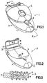
- the cooling device 3 which is shown on its own in Fig. 2 and of which a detail is shown in Fig.4, has a housing 7.
- the housing 7 comprises two dishes 8 and 9 that are made of plastics material and are connected together with a liquid-tight seal by a welded joint in the plastics material. Contained in the housing 7 is a cooling agent that comprises mainly water plus suitable additives.
- the cooling device 3 has a snap-in projection 10 by means of which the cooling device 3 can be connected to the depilation device 2, thus enabling the cooling device 3 and the depilation device 2 to form a working combination suitable for practical operation, namely the personal care system 1.
- the cooling device 3 also has a heat-conducting device 11.
- the heat-conducting device 11 comprises a portion 12 that is completely accommodated in the housing 7 and is in thermally conductive connection with the cooling agent, a second portion 14 that passes through the housing 7, that is to say through dish 8 of the housing in Fig.4, in a direction of passage indicated by an arrow 13, and a third portion 15 that is intended to cool an area to be cooled of a person's body.
- the heat-conducting device 11 comprises two extruded shaped profiles of aluminum, with the first extruded shaped profile forming the first portion 12 and the second extruded shaped profile forming the second portion 14 and the third portion 15.
- the two shaped profiles are connected together by a compressed joint formed by a compression operation.
- the first portion 12 is designed to be substantially plate-like and slightly angled so that its configuration is matched as closely as possible to the shape of the housing 7. It should be mentioned that the first portion 12 may also be formed by a stamped part.
- the third portion 15 comprises a connecting portion 16 that joins up in one piece with the second portion 14, a main cooling portion 15 that projects from the connecting portion 16 and a substantially U-shaped extra cooling portion 18 that is connected both to the connecting portion 16 and to a main cooling portion 17 and that surrounds an entry opening 19 that is provided to allow the hairs to enter and reach the set 4 of depilation disks.
- the heat-conducting device 11 is provided, at its second portion 14, with six groove-like depressions 21 that extend transversely to the direction of passage 13 and that open onto the outer surface 20 of the second portion 14.
- the six groove-like depressions 21 are of a substantially dovetailed shape in the present case.
- Each of the six depressions 21 is defined by a bottom wall 22 and two side-walls 23 and 24, which side-walls 23 and 24 merge on the one hand with the bottom wall 22 and on the other with the outer surface 20 of the second portion 14.
- the configuration of the side-walls 23 and 24 of the depressions is, in a particularly advantageous manner, such that portions 25 and 26 of the housing 7 hook behind the side-walls 23 and 24, which portions 25 and 26, like the entire housing dish 8, were produced by injection molding them around the second portion 14 of the heat-conducting device 11.
- the injection molding around the second portion 14 of the heat-conducting device 11 forms strip-like projections 31, the portions 25 and 26 of which are intended and designed to hook behind the side-walls 23 and 24 of the depressions.
- a second portion 14 of the heat-conducting device 11 of a cooling device 3 is shown diagrammatically in Fig. 5.
- the groove-like depressions 27 are each defined by a bottom wall 28 and two side-walls 29 and 30, with walls 28, 29 and 30 together being of an arcuate configuration and the configuration of the side-walls 29 and 30 of the depressions being such that portions of the strip-like projections (not shown in this case) on the housing of the cooling device 3 hook behind these side-walls 29 and 30.
- the groove-like depressions 21 and 27 are provided in the second portion 14 of the heat-conducting device 11 and the strip-like projections 31 are provided on the housing 7 of the cooling device 3. It is, however, also possible for the strip-like projections. to be provided on the heat-conducting device and the groove-like depressions to be provided in the housing, the advantage of which is that there is no weakening of the material of the heat-conducting device caused by depressions.
- a personal care system 1 that comprises a depilation device 2 and a cooling device 3.
- the provisions according to the invention may however be made, with advantage, not only in a personal care system with a depilation device but also in a personal care system employing a massaging unit or a circulation-stimulating unit having a skin-treatment appliance having needle-like or pin-like treatment members, in which personal care system a cooling device may equally well be used, with advantage, to reduce the sensation of pain.
Landscapes
- Health & Medical Sciences (AREA)
- General Health & Medical Sciences (AREA)
- Animal Behavior & Ethology (AREA)
- Thermal Sciences (AREA)
- Biomedical Technology (AREA)
- Heart & Thoracic Surgery (AREA)
- Vascular Medicine (AREA)
- Life Sciences & Earth Sciences (AREA)
- Physics & Mathematics (AREA)
- Engineering & Computer Science (AREA)
- Public Health (AREA)
- Veterinary Medicine (AREA)
- Pain & Pain Management (AREA)
- Thermotherapy And Cooling Therapy Devices (AREA)
- Dental Tools And Instruments Or Auxiliary Dental Instruments (AREA)
- Dry Shavers And Clippers (AREA)
Claims (12)
- Système de soins personnels (1) avec dispositif de soins personnels (2) et avec dispositif de refroidissement (3), lequel dispositif de refroidissement (3) a un logement (7) en matériau plastique, logement (7) dans lequel un agent réfrigérant est contenu, et lequel dispositif de refroidissement (3) a un dispositif conducteur de chaleur (11), le dispositif conducteur de chaleur (11) ayant une première partie (12) qui est logée dans le logement (7) et est en contact thermiquement conducteur avec l'agent réfrigérant, une deuxième partie (14) qui traverse le logement (7) dans une direction de passage (13) et une troisième partie (15) qui est destinée à refroidir une zone à refroidir d'un corps, caractérisé en ce qu'il est prévu entre la deuxième partie (14) du dispositif conducteur de chaleur (11) et la zone du logement (7) entourant la deuxième partie (14) du dispositif conducteur de chaleur (11) au moins une combinaison, se prolongeant transversalement à la direction de passage (13), d'au moins une dépression semblable à une gorge (21) et au moins une saillie semblable à une languette (31), et en ce que la au moins une dépression semblable à une gorge (21 ; 27) dans la au moins une combinaison est définie par deux parois latérales (23, 24 ; 29, 30) dont au moins une paroi latérale (23, 24 ; 29, 30) est d'une configuration telle qu'une partie (25, 26) de la saillie semblable à une languette (31) s'accroche derrière elle.
- Système de soins personnels (1) selon la revendication 1, dans lequel la configuration des deux parois latérales (23, 24 ; 29, 30) des dépressions est telle que deux parties (25, 26) de la saillie semblable à une languette (31) s'accrochent derrière elles.
- Système de soins personnels (1) selon la revendication 1, dans lequel au moins une dépression semblable à une gorge (21) est en forme de queue d'aronde.
- Système de soins personnels (1) selon la revendication 1, dans lequel au moins une combinaison comprend une dépression semblable à une gorge (27) qui est refermée sur elle-même comme un anneau et une saillie semblable à une languette qui est refermée sur elle-même comme un anneau.
- Système de soins personnels selon la revendication 1, dans lequel, dans la au moins une combinaison, la au moins une dépression semblable à une gorge (21, 27) est prévue dans la deuxième partie (14) du dispositif conducteur de chaleur (11) et la au moins une saillie semblable à une languette (31) est prévue sur la zone du logement (7) entourant la deuxième partie (14) du dispositif conducteur de chaleur (11).
- Système de soins personnels (1) selon la revendication 1, dans lequel le dispositif conducteur de chaleur (11) comprend au moins une partie extrudée d'un profil formé fait en aluminium.
- Dispositif de refroidissement (3) pour système de soins personnels (1), lequel dispositif de refroidissement (3) a un logement (7) en matériau plastique, logement (7) dans lequel un agent réfrigérant est contenu, le dispositif conducteur de chaleur (11) ayant une première partie (12) qui est logée dans le logement (7) et est en contact thermiquement conducteur avec l'agent réfrigérant, une deuxième partie (14) qui traverse le logement (7) dans une direction de passage (13) et une troisième partie (15) qui est destinée à refroidir une zone à refroidir d'un corps, caractérisé en ce qu'il est prévu entre la deuxième partie (14) du dispositif conducteur de chaleur (11) et la zone du logement (7) entourant la deuxième partie (14) du dispositif conducteur de chaleur (11) au moins une combinaison, se prolongeant transversalement à la direction de passage (13), d'au moins une dépression semblable à une gorge (21) et au moins une saillie semblable à une languette (31), et en ce que la au moins une dépression semblable à une gorge (21 ; 27) dans la au moins une combinaison est définie par deux parois latérales (23, 24 ; 29, 30) dont au moins une paroi latérale est d'une configuration telle qu'une partie (25, 26) de la saillie semblable à une languette (31) s'accroche derrière elle.
- Dispositif de refroidissement (3) selon la revendication 7, dans lequel la configuration des parois latérales (23, 24 ; 29, 30) des dépressions est telle que deux parties (25, 26) de la saillie semblable à une languette (31) s'accrochent derrière elles.
- Dispositif de refroidissement (3) selon la revendication 8, dans lequel la au moins une dépression semblable à une gorge (21) est en forme de queue d'aronde.
- Dispositif de refroidissement (3) selon la revendication 7, dans lequel au moins une combinaison comprend une dépression semblable à une gorge (27) qui est refermée sur elle-même comme un anneau et une saillie semblable à une languette (31) qui est refermée sur elle-même comme un anneau.
- Dispositif de refroidissement (3) selon la revendication 7, dans lequel, dans la au moins une combinaison, la au moins une dépression semblable à une gorge (21 ; 27) est prévue dans la deuxième partie (14) du dispositif conducteur de chaleur (11) et la au moins une saillie semblable à une languette (31) est prévue sur la zone du logement (7) entourant la deuxième partie (14) du dispositif conducteur de chaleur (11).
- Dispositif de refroidissement (3) selon la revendication 7, dans lequel le dispositif conducteur de chaleur (11) comprend au moins une partie extrudée d'un profil formé fait en aluminium.
Priority Applications (1)
| Application Number | Priority Date | Filing Date | Title |
|---|---|---|---|
| EP03737396A EP1478312B1 (fr) | 2002-02-06 | 2003-01-23 | Systeme de soins personnels avec dispositif de soins personnels et dispositif de refroidissement |
Applications Claiming Priority (4)
| Application Number | Priority Date | Filing Date | Title |
|---|---|---|---|
| EP02100111 | 2002-02-06 | ||
| EP02100111 | 2002-02-06 | ||
| PCT/IB2003/000185 WO2003065948A1 (fr) | 2002-02-06 | 2003-01-23 | Systeme de soins personnels avec dispositif de soins personnels et dispositif de refroidissement |
| EP03737396A EP1478312B1 (fr) | 2002-02-06 | 2003-01-23 | Systeme de soins personnels avec dispositif de soins personnels et dispositif de refroidissement |
Publications (2)
| Publication Number | Publication Date |
|---|---|
| EP1478312A1 EP1478312A1 (fr) | 2004-11-24 |
| EP1478312B1 true EP1478312B1 (fr) | 2006-09-13 |
Family
ID=27675736
Family Applications (1)
| Application Number | Title | Priority Date | Filing Date |
|---|---|---|---|
| EP03737396A Expired - Lifetime EP1478312B1 (fr) | 2002-02-06 | 2003-01-23 | Systeme de soins personnels avec dispositif de soins personnels et dispositif de refroidissement |
Country Status (8)
| Country | Link |
|---|---|
| US (1) | US20050080432A1 (fr) |
| EP (1) | EP1478312B1 (fr) |
| JP (1) | JP4257210B2 (fr) |
| CN (1) | CN1273096C (fr) |
| AT (1) | ATE339169T1 (fr) |
| AU (1) | AU2003201135A1 (fr) |
| DE (1) | DE60308326T2 (fr) |
| WO (1) | WO2003065948A1 (fr) |
Families Citing this family (9)
| Publication number | Priority date | Publication date | Assignee | Title |
|---|---|---|---|---|
| JP2008502403A (ja) | 2004-06-14 | 2008-01-31 | コーニンクレッカ フィリップス エレクトロニクス エヌ ヴィ | 可動冷却表面を備えるパーソナルケアシステム |
| RS52213B (sr) * | 2004-09-03 | 2012-10-31 | Genentech, Inc. | Humanizovani anti-beta7 antagonisti i njihove primene |
| EP1816925B1 (fr) * | 2004-09-30 | 2010-09-15 | Koninklijke Philips Electronics N.V. | Appareil d'epilation |
| USD541473S1 (en) * | 2005-08-16 | 2007-04-24 | Koninklijke Philips Electronics N.V. | Epilator with ice cube |
| RU2327399C2 (ru) * | 2006-02-03 | 2008-06-27 | Государственное Образовательное Учреждение Высшего Профессионального Образования "Дагестанский Государственный Технический Университет" (Дгту) | Термоэлектрическая насадка к эпилятору |
| CN101848659B (zh) * | 2008-02-22 | 2012-12-26 | 皇家飞利浦电子股份有限公司 | 具有可互换帽的脱毛器 |
| DE102008014016A1 (de) * | 2008-03-13 | 2009-09-24 | Braun Gmbh | Haarentfernungsgerät |
| WO2009118670A2 (fr) | 2008-03-25 | 2009-10-01 | Koninklijke Philips Electronics N.V. | Poste d’accueil et procédé de refroidissement pour un dispositif de traitement de la peau |
| KR101540645B1 (ko) * | 2014-11-19 | 2015-08-03 | (주)하배런메디엔뷰티 | 제모기와 냉각기로 구성된 제모 장치 |
Family Cites Families (7)
| Publication number | Priority date | Publication date | Assignee | Title |
|---|---|---|---|---|
| US1209948A (en) * | 1915-06-15 | 1916-12-26 | Flannery Bolt Co | Bar for bolt-blanks. |
| US1692529A (en) * | 1926-01-29 | 1928-11-20 | American Luigi Corp | Machine for making hollow tubes or conductors |
| US2793571A (en) * | 1949-11-15 | 1957-05-28 | Us Rubber Co | Suction press roll |
| JPS59120704A (ja) * | 1982-12-27 | 1984-07-12 | Toshiba Corp | 超高温耐熱壁体 |
| IL86872A0 (en) * | 1988-06-27 | 1988-11-30 | Levin Alexander | Auxilliary device for hairplucking apparatus |
| FR2709932B1 (fr) * | 1993-09-15 | 1995-11-17 | Seb Sa | Appareil à épilation mécanique par arrachage de poils sur la peau. |
| DE60004949T2 (de) * | 1999-06-11 | 2004-07-15 | Koninklijke Philips Electronics N.V. | Enthaarungssystem mit enthaarungsvorrichtung und kühlvorrichtung mit bestimmten parametern |
-
2003
- 2003-01-23 CN CN03803338.0A patent/CN1273096C/zh not_active Expired - Fee Related
- 2003-01-23 JP JP2003565377A patent/JP4257210B2/ja not_active Expired - Fee Related
- 2003-01-23 WO PCT/IB2003/000185 patent/WO2003065948A1/fr not_active Ceased
- 2003-01-23 AT AT03737396T patent/ATE339169T1/de not_active IP Right Cessation
- 2003-01-23 EP EP03737396A patent/EP1478312B1/fr not_active Expired - Lifetime
- 2003-01-23 AU AU2003201135A patent/AU2003201135A1/en not_active Abandoned
- 2003-01-23 DE DE60308326T patent/DE60308326T2/de not_active Expired - Lifetime
- 2003-01-23 US US10/503,423 patent/US20050080432A1/en not_active Abandoned
Also Published As
| Publication number | Publication date |
|---|---|
| US20050080432A1 (en) | 2005-04-14 |
| JP4257210B2 (ja) | 2009-04-22 |
| JP2005516675A (ja) | 2005-06-09 |
| AU2003201135A1 (en) | 2003-09-02 |
| DE60308326D1 (de) | 2006-10-26 |
| CN1627926A (zh) | 2005-06-15 |
| CN1273096C (zh) | 2006-09-06 |
| ATE339169T1 (de) | 2006-10-15 |
| EP1478312A1 (fr) | 2004-11-24 |
| DE60308326T2 (de) | 2007-04-19 |
| WO2003065948A1 (fr) | 2003-08-14 |
Similar Documents
| Publication | Publication Date | Title |
|---|---|---|
| EP1478312B1 (fr) | Systeme de soins personnels avec dispositif de soins personnels et dispositif de refroidissement | |
| US6185941B1 (en) | Thermoelectric converter | |
| US10655906B2 (en) | Refrigerator | |
| HUP0104028A2 (hu) | Tömítés profilos külsőajtajú hűtőberendezéshez | |
| EP0942245A2 (fr) | Porte pour réfrigérateur ménager | |
| CN215020199U (zh) | 一种额头制冷机 | |
| US11826309B2 (en) | Therapy device | |
| JPH1089836A (ja) | 冷蔵庫の排水装置 | |
| JP2018128207A (ja) | 冷蔵庫 | |
| US20220287872A1 (en) | Double-shelled cryolipolysis applicator | |
| CN2816705Y (zh) | 轻便冷藏箱 | |
| JP3086590B2 (ja) | 断熱箱体 | |
| KR0156370B1 (ko) | 냉장고의 냉기순환장치 | |
| RU850U1 (ru) | Термоэлектрический холодильник | |
| KR200186785Y1 (ko) | 내외상 연결 가스킷 | |
| KR0127434Y1 (ko) | 냉장고의 사이드덕트 | |
| JPS5856539Y2 (ja) | 冷凍室用排水装置 | |
| JPH10160331A (ja) | 冷蔵庫の扉 | |
| ES2182654B1 (es) | Refrigerador. | |
| JPS6221896Y2 (fr) | ||
| KR200141351Y1 (ko) | 쇼케이스의 라이너프레임 설치구조 | |
| KR200216027Y1 (ko) | 김치 저장고의 열전모듈 고정구 | |
| KR19990000559U (ko) | 냉장고의 도어열림장치 | |
| KR19980051046U (ko) | 자동차의 글로브 박스를 이용한 온장고 | |
| JPS618894A (ja) | 高周波加熱装置 |
Legal Events
| Date | Code | Title | Description |
|---|---|---|---|
| PUAI | Public reference made under article 153(3) epc to a published international application that has entered the european phase |
Free format text: ORIGINAL CODE: 0009012 |
|
| 17P | Request for examination filed |
Effective date: 20040906 |
|
| AK | Designated contracting states |
Kind code of ref document: A1 Designated state(s): AT BE BG CH CY CZ DE DK EE ES FI FR GB GR HU IE IT LI LU MC NL PT SE SI SK TR |
|
| AX | Request for extension of the european patent |
Extension state: AL LT LV MK RO |
|
| GRAP | Despatch of communication of intention to grant a patent |
Free format text: ORIGINAL CODE: EPIDOSNIGR1 |
|
| GRAS | Grant fee paid |
Free format text: ORIGINAL CODE: EPIDOSNIGR3 |
|
| GRAA | (expected) grant |
Free format text: ORIGINAL CODE: 0009210 |
|
| AK | Designated contracting states |
Kind code of ref document: B1 Designated state(s): AT BE BG CH CY CZ DE DK EE ES FI FR GB GR HU IE IT LI LU MC NL PT SE SI SK TR |
|
| PG25 | Lapsed in a contracting state [announced via postgrant information from national office to epo] |
Ref country code: IT Free format text: LAPSE BECAUSE OF FAILURE TO SUBMIT A TRANSLATION OF THE DESCRIPTION OR TO PAY THE FEE WITHIN THE PRESCRIBED TIME-LIMIT;WARNING: LAPSES OF ITALIAN PATENTS WITH EFFECTIVE DATE BEFORE 2007 MAY HAVE OCCURRED AT ANY TIME BEFORE 2007. THE CORRECT EFFECTIVE DATE MAY BE DIFFERENT FROM THE ONE RECORDED. Effective date: 20060913 Ref country code: FI Free format text: LAPSE BECAUSE OF FAILURE TO SUBMIT A TRANSLATION OF THE DESCRIPTION OR TO PAY THE FEE WITHIN THE PRESCRIBED TIME-LIMIT Effective date: 20060913 Ref country code: BE Free format text: LAPSE BECAUSE OF FAILURE TO SUBMIT A TRANSLATION OF THE DESCRIPTION OR TO PAY THE FEE WITHIN THE PRESCRIBED TIME-LIMIT Effective date: 20060913 Ref country code: AT Free format text: LAPSE BECAUSE OF FAILURE TO SUBMIT A TRANSLATION OF THE DESCRIPTION OR TO PAY THE FEE WITHIN THE PRESCRIBED TIME-LIMIT Effective date: 20060913 Ref country code: SI Free format text: LAPSE BECAUSE OF FAILURE TO SUBMIT A TRANSLATION OF THE DESCRIPTION OR TO PAY THE FEE WITHIN THE PRESCRIBED TIME-LIMIT Effective date: 20060913 Ref country code: CH Free format text: LAPSE BECAUSE OF FAILURE TO SUBMIT A TRANSLATION OF THE DESCRIPTION OR TO PAY THE FEE WITHIN THE PRESCRIBED TIME-LIMIT Effective date: 20060913 Ref country code: LI Free format text: LAPSE BECAUSE OF FAILURE TO SUBMIT A TRANSLATION OF THE DESCRIPTION OR TO PAY THE FEE WITHIN THE PRESCRIBED TIME-LIMIT Effective date: 20060913 Ref country code: CZ Free format text: LAPSE BECAUSE OF FAILURE TO SUBMIT A TRANSLATION OF THE DESCRIPTION OR TO PAY THE FEE WITHIN THE PRESCRIBED TIME-LIMIT Effective date: 20060913 Ref country code: NL Free format text: LAPSE BECAUSE OF FAILURE TO SUBMIT A TRANSLATION OF THE DESCRIPTION OR TO PAY THE FEE WITHIN THE PRESCRIBED TIME-LIMIT Effective date: 20060913 Ref country code: SK Free format text: LAPSE BECAUSE OF FAILURE TO SUBMIT A TRANSLATION OF THE DESCRIPTION OR TO PAY THE FEE WITHIN THE PRESCRIBED TIME-LIMIT Effective date: 20060913 |
|
| REG | Reference to a national code |
Ref country code: GB Ref legal event code: FG4D |
|
| REG | Reference to a national code |
Ref country code: CH Ref legal event code: EP |
|
| REG | Reference to a national code |
Ref country code: IE Ref legal event code: FG4D |
|
| REF | Corresponds to: |
Ref document number: 60308326 Country of ref document: DE Date of ref document: 20061026 Kind code of ref document: P |
|
| PG25 | Lapsed in a contracting state [announced via postgrant information from national office to epo] |
Ref country code: SE Free format text: LAPSE BECAUSE OF FAILURE TO SUBMIT A TRANSLATION OF THE DESCRIPTION OR TO PAY THE FEE WITHIN THE PRESCRIBED TIME-LIMIT Effective date: 20061213 Ref country code: BG Free format text: LAPSE BECAUSE OF FAILURE TO SUBMIT A TRANSLATION OF THE DESCRIPTION OR TO PAY THE FEE WITHIN THE PRESCRIBED TIME-LIMIT Effective date: 20061213 Ref country code: DK Free format text: LAPSE BECAUSE OF FAILURE TO SUBMIT A TRANSLATION OF THE DESCRIPTION OR TO PAY THE FEE WITHIN THE PRESCRIBED TIME-LIMIT Effective date: 20061213 |
|
| PG25 | Lapsed in a contracting state [announced via postgrant information from national office to epo] |
Ref country code: ES Free format text: LAPSE BECAUSE OF FAILURE TO SUBMIT A TRANSLATION OF THE DESCRIPTION OR TO PAY THE FEE WITHIN THE PRESCRIBED TIME-LIMIT Effective date: 20061224 |
|
| PG25 | Lapsed in a contracting state [announced via postgrant information from national office to epo] |
Ref country code: IE Free format text: LAPSE BECAUSE OF NON-PAYMENT OF DUE FEES Effective date: 20070123 |
|
| PG25 | Lapsed in a contracting state [announced via postgrant information from national office to epo] |
Ref country code: MC Free format text: LAPSE BECAUSE OF NON-PAYMENT OF DUE FEES Effective date: 20070131 |
|
| NLV1 | Nl: lapsed or annulled due to failure to fulfill the requirements of art. 29p and 29m of the patents act | ||
| PG25 | Lapsed in a contracting state [announced via postgrant information from national office to epo] |
Ref country code: PT Free format text: LAPSE BECAUSE OF FAILURE TO SUBMIT A TRANSLATION OF THE DESCRIPTION OR TO PAY THE FEE WITHIN THE PRESCRIBED TIME-LIMIT Effective date: 20070302 |
|
| REG | Reference to a national code |
Ref country code: CH Ref legal event code: PL |
|
| ET | Fr: translation filed | ||
| PLBE | No opposition filed within time limit |
Free format text: ORIGINAL CODE: 0009261 |
|
| STAA | Information on the status of an ep patent application or granted ep patent |
Free format text: STATUS: NO OPPOSITION FILED WITHIN TIME LIMIT |
|
| 26N | No opposition filed |
Effective date: 20070614 |
|
| PG25 | Lapsed in a contracting state [announced via postgrant information from national office to epo] |
Ref country code: GR Free format text: LAPSE BECAUSE OF FAILURE TO SUBMIT A TRANSLATION OF THE DESCRIPTION OR TO PAY THE FEE WITHIN THE PRESCRIBED TIME-LIMIT Effective date: 20061214 |
|
| PG25 | Lapsed in a contracting state [announced via postgrant information from national office to epo] |
Ref country code: EE Free format text: LAPSE BECAUSE OF FAILURE TO SUBMIT A TRANSLATION OF THE DESCRIPTION OR TO PAY THE FEE WITHIN THE PRESCRIBED TIME-LIMIT Effective date: 20060913 |
|
| PG25 | Lapsed in a contracting state [announced via postgrant information from national office to epo] |
Ref country code: CY Free format text: LAPSE BECAUSE OF FAILURE TO SUBMIT A TRANSLATION OF THE DESCRIPTION OR TO PAY THE FEE WITHIN THE PRESCRIBED TIME-LIMIT Effective date: 20060913 Ref country code: LU Free format text: LAPSE BECAUSE OF NON-PAYMENT OF DUE FEES Effective date: 20070123 |
|
| PG25 | Lapsed in a contracting state [announced via postgrant information from national office to epo] |
Ref country code: TR Free format text: LAPSE BECAUSE OF FAILURE TO SUBMIT A TRANSLATION OF THE DESCRIPTION OR TO PAY THE FEE WITHIN THE PRESCRIBED TIME-LIMIT Effective date: 20060913 Ref country code: HU Free format text: LAPSE BECAUSE OF FAILURE TO SUBMIT A TRANSLATION OF THE DESCRIPTION OR TO PAY THE FEE WITHIN THE PRESCRIBED TIME-LIMIT Effective date: 20070314 |
|
| REG | Reference to a national code |
Ref country code: DE Ref legal event code: R082 Ref document number: 60308326 Country of ref document: DE Representative=s name: VOLMER, GEORG, DIPL.-ING., DE |
|
| REG | Reference to a national code |
Ref country code: DE Ref legal event code: R082 Ref document number: 60308326 Country of ref document: DE Representative=s name: VOLMER, GEORG, DIPL.-ING., DE Effective date: 20140331 Ref country code: DE Ref legal event code: R081 Ref document number: 60308326 Country of ref document: DE Owner name: KONINKLIJKE PHILIPS N.V., NL Free format text: FORMER OWNER: KONINKLIJKE PHILIPS ELECTRONICS N.V., EINDHOVEN, NL Effective date: 20140331 Ref country code: DE Ref legal event code: R082 Ref document number: 60308326 Country of ref document: DE Representative=s name: MEISSNER BOLTE PATENTANWAELTE RECHTSANWAELTE P, DE Effective date: 20140331 |
|
| REG | Reference to a national code |
Ref country code: FR Ref legal event code: CA Effective date: 20141126 Ref country code: FR Ref legal event code: CD Owner name: KONINKLIJKE PHILIPS N.V., NL Effective date: 20141126 |
|
| REG | Reference to a national code |
Ref country code: FR Ref legal event code: PLFP Year of fee payment: 14 |
|
| PGFP | Annual fee paid to national office [announced via postgrant information from national office to epo] |
Ref country code: DE Payment date: 20160331 Year of fee payment: 14 |
|
| PGFP | Annual fee paid to national office [announced via postgrant information from national office to epo] |
Ref country code: FR Payment date: 20160129 Year of fee payment: 14 Ref country code: GB Payment date: 20160129 Year of fee payment: 14 |
|
| REG | Reference to a national code |
Ref country code: DE Ref legal event code: R082 Ref document number: 60308326 Country of ref document: DE Representative=s name: MEISSNER BOLTE PATENTANWAELTE RECHTSANWAELTE P, DE |
|
| REG | Reference to a national code |
Ref country code: DE Ref legal event code: R119 Ref document number: 60308326 Country of ref document: DE |
|
| GBPC | Gb: european patent ceased through non-payment of renewal fee |
Effective date: 20170123 |
|
| REG | Reference to a national code |
Ref country code: FR Ref legal event code: ST Effective date: 20170929 |
|
| PG25 | Lapsed in a contracting state [announced via postgrant information from national office to epo] |
Ref country code: FR Free format text: LAPSE BECAUSE OF NON-PAYMENT OF DUE FEES Effective date: 20170131 |
|
| PG25 | Lapsed in a contracting state [announced via postgrant information from national office to epo] |
Ref country code: DE Free format text: LAPSE BECAUSE OF NON-PAYMENT OF DUE FEES Effective date: 20170801 Ref country code: GB Free format text: LAPSE BECAUSE OF NON-PAYMENT OF DUE FEES Effective date: 20170123 |