EP1479564A2 - dispositif de protection pour intérieur véhicule - Google Patents
dispositif de protection pour intérieur véhicule Download PDFInfo
- Publication number
- EP1479564A2 EP1479564A2 EP04010039A EP04010039A EP1479564A2 EP 1479564 A2 EP1479564 A2 EP 1479564A2 EP 04010039 A EP04010039 A EP 04010039A EP 04010039 A EP04010039 A EP 04010039A EP 1479564 A2 EP1479564 A2 EP 1479564A2
- Authority
- EP
- European Patent Office
- Prior art keywords
- fabric
- flat structure
- protective
- protective device
- guide
- Prior art date
- Legal status (The legal status is an assumption and is not a legal conclusion. Google has not performed a legal analysis and makes no representation as to the accuracy of the status listed.)
- Granted
Links
Images



Classifications
-
- A—HUMAN NECESSITIES
- A47—FURNITURE; DOMESTIC ARTICLES OR APPLIANCES; COFFEE MILLS; SPICE MILLS; SUCTION CLEANERS IN GENERAL
- A47J—KITCHEN EQUIPMENT; COFFEE MILLS; SPICE MILLS; APPARATUS FOR MAKING BEVERAGES
- A47J37/00—Baking; Roasting; Grilling; Frying
- A47J37/06—Roasters; Grills; Sandwich grills
- A47J37/067—Horizontally disposed broiling griddles
-
- B—PERFORMING OPERATIONS; TRANSPORTING
- B60—VEHICLES IN GENERAL
- B60R—VEHICLES, VEHICLE FITTINGS, OR VEHICLE PARTS, NOT OTHERWISE PROVIDED FOR
- B60R5/00—Compartments within vehicle body primarily intended or sufficiently spacious for trunks, suit-cases, or the like
- B60R5/04—Compartments within vehicle body primarily intended or sufficiently spacious for trunks, suit-cases, or the like arranged at rear of vehicle
- B60R5/044—Compartments within vehicle body primarily intended or sufficiently spacious for trunks, suit-cases, or the like arranged at rear of vehicle luggage covering means, e.g. parcel shelves
- B60R5/045—Compartments within vehicle body primarily intended or sufficiently spacious for trunks, suit-cases, or the like arranged at rear of vehicle luggage covering means, e.g. parcel shelves collapsible or transformable
- B60R5/047—Compartments within vehicle body primarily intended or sufficiently spacious for trunks, suit-cases, or the like arranged at rear of vehicle luggage covering means, e.g. parcel shelves collapsible or transformable collapsible by rolling-up
-
- A—HUMAN NECESSITIES
- A47—FURNITURE; DOMESTIC ARTICLES OR APPLIANCES; COFFEE MILLS; SPICE MILLS; SUCTION CLEANERS IN GENERAL
- A47J—KITCHEN EQUIPMENT; COFFEE MILLS; SPICE MILLS; APPARATUS FOR MAKING BEVERAGES
- A47J37/00—Baking; Roasting; Grilling; Frying
- A47J37/06—Roasters; Grills; Sandwich grills
- A47J37/0694—Broiling racks
-
- B—PERFORMING OPERATIONS; TRANSPORTING
- B60—VEHICLES IN GENERAL
- B60R—VEHICLES, VEHICLE FITTINGS, OR VEHICLE PARTS, NOT OTHERWISE PROVIDED FOR
- B60R21/00—Arrangements or fittings on vehicles for protecting or preventing injuries to occupants or pedestrians in case of accidents or other traffic risks
- B60R21/02—Occupant safety arrangements or fittings, e.g. crash pads
- B60R21/06—Safety nets, transparent sheets, curtains, or the like, e.g. between occupants and glass
-
- A—HUMAN NECESSITIES
- A47—FURNITURE; DOMESTIC ARTICLES OR APPLIANCES; COFFEE MILLS; SPICE MILLS; SUCTION CLEANERS IN GENERAL
- A47B—TABLES; DESKS; OFFICE FURNITURE; CABINETS; DRAWERS; GENERAL DETAILS OF FURNITURE
- A47B13/00—Details of tables or desks
- A47B13/02—Underframes
-
- A—HUMAN NECESSITIES
- A47—FURNITURE; DOMESTIC ARTICLES OR APPLIANCES; COFFEE MILLS; SPICE MILLS; SUCTION CLEANERS IN GENERAL
- A47B—TABLES; DESKS; OFFICE FURNITURE; CABINETS; DRAWERS; GENERAL DETAILS OF FURNITURE
- A47B13/00—Details of tables or desks
- A47B13/08—Table tops; Rims therefor
-
- A—HUMAN NECESSITIES
- A47—FURNITURE; DOMESTIC ARTICLES OR APPLIANCES; COFFEE MILLS; SPICE MILLS; SUCTION CLEANERS IN GENERAL
- A47B—TABLES; DESKS; OFFICE FURNITURE; CABINETS; DRAWERS; GENERAL DETAILS OF FURNITURE
- A47B31/00—Service or tea tables, trolleys, or wagons
- A47B31/02—Service or tea tables, trolleys, or wagons with heating, cooling or ventilating means
Definitions
- the invention relates to a protective device for an interior of a Motor vehicle with a flexible fabric that between a compactly stored rest position and at least one extended Protection position is movably supported by guide means.
- Such a protective device is in the form of a loading space cover known from DE 199 44 948 C1.
- the well-known load compartment cover has a flexible sheet that is in a cassette housing is held on a winding shaft and unrollable.
- the cassette case is in the area of a backrest arrangement of a rear bench seat positioned.
- a dimensionally stable In a front end area in the pull-out direction a dimensionally stable, extending over the width of the fabric Pull-out bar provided with its lateral ends over the side edges of the fabric protrudes.
- the side ends of the pull-out bar are arranged in the side guide rails of the cargo area, in which longitudinally movable carriers are provided, the the lateral ends of the pull-out bar with limited force along the Take the guide rails with you.
- the drivers are electrical Drive device driven, the opposite Carriers are preferably synchronized with each other to create a parallel Extending or inserting movement of the pull-out bar and thus the To achieve fabric.
- the fabric is therefore between one Compactly wound rest position integrated in the cassette housing and a a hold of the motor vehicle approximately horizontally covering protective position movably mounted.
- the object of the invention is a protective device of the aforementioned Way of creating, by means of simple means different Protection states for the interior of the motor vehicle can be implemented are.
- the guide means are designed in this way are that the fabric between a first, approximately horizontally extended protective position and a second, approximately vertically extended protective position is shiftable.
- the solution is used both as a horizontal cover for the cargo area as well as an approximately vertically aligned separating device.
- the fabric preferably at about the height or just below pulled out of a vehicle curb and covers the cargo space.
- the function as a separating device is approximately vertical pulled out to about a headlining, creating a passenger compartment is separated from a cargo space within the interior.
- the cargo hold function of the fabric is primarily a privacy screen created to protect you from outside the vehicle To prevent insight into the cargo hold.
- the fabric is in this hold function preferably designed opaque.
- the vertically spanned Separation function is to prevent the fabric, in particular with a strong vehicle deceleration objects from the Cargo space to be thrown into the passenger compartment.
- the fabric thus has a retention function for cargo hold.
- the fabric In about vertically extended protective position, the fabric is preferred translucent enough for a driver to look into the Rear-view mirror through the spanned fabric through the action behind the vehicle, especially those behind it Road traffic, can watch.
- the fabric can do this preferably consist of a woven or knitted fabric that such is designed like a net or lattice, that at a glance at the spanned
- the fabric is at an acute angle looks largely opaque, whereas when you look into a right angle to the spanned surface of the fabric a review is possible.
- In the horizontal cargo hold function can thus be seen from outside the vehicle Vehicle interior, which inevitably at an acute angle to the fabric strikes, do not allow a view through the fabric.
- the desired privacy screen in the load compartment cover function is guaranteed.
- fixing means for locking the fabric provided in the respective protective position.
- the fixative serve on the one hand to make the fabric in the approximately vertical or to keep in the approximately horizontal protection position.
- You can also the fixing means can be designed such that the fabric also positioned when objects are immersed in the fabric remains. This is particularly advantageous if through the fabric In the approximately vertically spanned protective position, restraint protection for those thrown out of the hold in the direction of the passenger compartment Objects is formed.
- the fixatives limit the Dodge path of the fabric so that the fabric essentially is kept taut. This makes it more difficult when immersed Objects in the fabric are only a comparative little deformation and bulging of the fabric, so that People who are on the rear bench seat, through which from the Load space objects thrown forward are not injured can.
- the guide means have a Linear guide arrangement on opposite sides of the vehicle mutually parallel, rectilinear and / or curved Has leadership profiles.
- the opposite ones preferably run Guiding profiles along corresponding vehicle pillars the body support structure to a roof frame area and further along the respective roof frame area in the vehicle longitudinal direction.
- the guide profiles with the body support structure are preferably anchored and adapted to an interior lining or integrated into this.
- the guide profiles are preferably made of Backdrops designed by the appropriate contour adjusted between the vehicle curb and a roof area Guide rails are formed.
- the fabric is one Return arrangement associated with a retraction force on the fabric in the direction of the compact resting position.
- the return arrangement by a spring accumulator or a spring motor educated.
- This return arrangement serves on the one hand to the fabric from a corresponding protective position to the rest position can be traced back.
- the return arrangement also serves also on the fabric in the respective protective position a return load that tightens or tightens the fabric exercise.
- the end area of the fabric is dimensionally stable across the direction of extension designed and has lateral bearing elements that match the guide profiles stay in contact.
- the bearing elements are on or preferably sliding or rolling in the guide profiles longitudinally displaceable.
- the bearing elements and guide profiles are preferred at least in the end areas of the guide profiles, that define the protective positions of the fabric, such positively connected with each other by a strong vehicle deceleration caused loads on the fabric without the location elements being different from the guide profiles separate.
- the bearing elements are thus tear-proof held in or on the guide profiles. With this solution it is guaranteed that crash protection for the fabric and can thus be achieved for the entire protective device.
- the guide means in the area a separation device is assigned to at least one protective position, which a controlled release of the front end area from the guide means allows.
- a corresponding control can be done manually by grasping the front end area or automatically by a suitable control device.
- the separator can be in be carried out in different ways. It is special possible that when designing the leadership means as leadership profiles at least one guide profile on at least one End area is designed so open that a manual release of the Frontal area of the fabric, i.e. loosening the bearing elements, is made possible by the corresponding management profiling. alternative it is also possible to provide separators that according to Kind of releasable closures are executed.
- a drive device which in at least one direction is a displacement of the end region achieved along the guide profiles.
- a corresponding drive is provided at least in the pull-out direction, the mechanically, in particular in the form of a spring accumulator, electrically, be carried out pneumatically, hydraulically or in some other way can.
- a linear actuator is particularly preferred as the drive device assigned to the guide profiles on the frontal areas of the fabric in at least one direction of the longitudinal extent that acts on leadership profiles.
- another flexible flat structure is provided that parallel to a horizontal pull-out track of the first sheet is arranged approximately horizontally extendable and that is at least largely opaque.
- This configuration is particularly advantageous if the first fabric in its about vertical protection position is transferred. Through the further fabric it is possible, despite being in its approximately vertical protective position transferred the first fabric to privacy the floor of the hold or in another way below to achieve objects arranged on a vehicle curb.
- the further flat structure is held on a winding shaft, the housing for receiving the is assigned to the first fabric.
- both fabrics are arranged compactly adjacent to each other. Are preferred both fabrics are housed in a common housing.
- the further flat structure is in the area of the arrangement of the housing for the first flat structure opposite interior boundary surface stored and counter to an extraction direction of the first sheet Extendable.
- a load compartment wall is provided as an interior boundary surface. This can be part of a fixed body section or also part of a movable body part, in particular a tailgate.
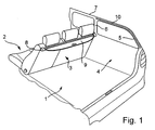
- a motor vehicle is according to FIGS. 1 to 4 as a station wagon executed, the one in a vehicle interior Passenger compartment 2 and the other includes a cargo space 1.
- the cargo hold 1 is arranged in a rear area of the motor vehicle and accessible from the outside via a tailgate, not shown.
- the cargo space 1 is forward through in the longitudinal direction of the vehicle limited a backrest arrangement 3 of a rear bench seat.
- On opposite A side wall 4 is provided on each side of the vehicle, which limits the cargo space 1 laterally.
- Each side wall 4 is up to approximately at the level of a vehicle curb, i.e. to about the level of the lower edges from window openings, starting from a load floor executed closed and preferably with appropriate Provide interior trim parts.
- the Support column sections 5, 6 and the roof frame area 7 are parts of one Body support structure, not shown, which in the area of Vehicle interior by appropriate, unspecified Fairings are covered.
- the cassette housing 8 is known in principle Way, a winding shaft rotatably mounted on the one and unrollable flexible sheet 11 (Fig. 2) is held.
- the fabric 11 is through an unspecified slot in the Cassette housing 8 led out of this.
- the cassette case extends over almost the entire width of the load compartment 1.
- In the sheet 11 also extends accordingly almost over the entire width of the cargo area 1.
- the fabric 11 is completely on the winding shaft in its compactly stored rest position rolled up.
- the front end area 9 extends over the entire width of the fabric 11 and is dimensionally stable.
- the forehead area 9 has one across the entire width of the fabric 11 extending, dimensionally stable pull-out bar 12, with their opposite Front ends laterally over the respective side edge of the fabric 11 protrudes. Every forehead is with one bearing element 13 described in more detail below.
- the fabric 11 is both approximately horizontal in FIG. 2 Protection position as well as in a shown in Fig. 4, approximately vertically extended protective position extendable.
- the roller blind shaft is integrated into the cassette housing 8
- Return arrangement preferably a return spring, in the winding direction of the fabric 11 is torsionally loaded, so that a corresponding Return force of the return arrangement the fabric 11 holds taut in both protective positions.
- This blocking device secures the fabric in the event of a strong one Vehicle deceleration or when immersing heavy objects into the fabric against an extraction process. Doing so in particular a sudden or jerky pulling out of the fabric prevented.
- This blocking device is preferably only in vertical, but not approximately horizontal, protective position of the fabric 11 effective.
- the fabric 11 consists of a textile woven or knit material, which is designed in a mesh or grid-like manner that the Fabric 11 at an oblique angle, in particular one acute viewing angle between 0 ° and 60 °, is opaque. At a glance through the stretched fabric 11 in a right Angle, i.e. at an angle of approximately 90 °, the fabric is 11 translucent. This allows the fabric 11 in its approximately 4 a perspective view for a driver of the motor vehicle, if this is through a rear-view mirror in the vehicle interior, for example, the rear traffic want to watch.
- the flat structure 11 is with its front end region 9 and in particular with the pull-out bar 12 and the bearing elements 13 in lateral Guide profiles 10 held.
- the guide profiles 10 are designed as guide rails 14 in the form of hollow profiles, each form a guide 10 open to the vehicle interior.
- to Guide of the front end area 9 and the pull-out bar 12 are on opposite Vehicle sides two parallel to each other Guide rails 14 provided with the body support structure are firmly connected.
- Each guide rail 14 points from a rear of the cargo space 1 a first, sloping section on, which runs along the rear pillar section 5.
- each guide rail is curved, to follow the body-side transition.
- each guide rail 14 extends along the respective roof frame section 7 to about the level of a part of the C-pillar Support column section 6, which is approximately at the level of the backrest arrangement 3 the rear bench seat is positioned.
- the pull-out bar 12 is in her stop position aligned in the vehicle transverse direction along the link guide both guide rails 14 displaceable (see also dash-dotted Representation in Figs. 2 and 4).
- the roughly horizontal protective position of the fabric 11 (Fig. 2) and the approximately vertical protective position of the fabric 11 (Fig. 4) are by opposite End positions of the guide rails 14 and the link guides 10 defined and limited.
- the pull-out bar 12 can be in the guide rails manually moved between the two protective positions.
- FIG Pull-out bar 12 it is provided as shown in FIG Pull-out bar 12 and thus the fabric 11 by a drive device to shift in the guide rails.
- the drive device is designed the same or similar to that from DE 199 44 948 C1 known drive device, so that for additional disclosure reference is made to this prior art.
- Such a drive device preferably has a drive motor as it 6 is provided with the reference number 19.
- the opposite Front ends of the pull-out bar 12 are in each guide rail held on a longitudinally movable driver 15 by Traction and / or pressure means 16 by actuating the drive motor is movable along the backdrop guide. This makes it automatic and positively controlled displacement of the fabric 11 in the desired protection position possible.
- the driver 15 can be designed so that the pull-out bar 12 can be released depending on the force.
- the drivers can secure the pull-out rail with no force and carry it with you so that no force-dependent release of the pull-out bar can be achieved is.
- a release can only be controlled in a defined manner by a separating device respectively
- the front end area 9 is formed as a dimensionally stable contour part is designed so that it has a contour on the inside of the tailgate follows in order to achieve a flush conclusion here.
- the contour part is also shaped so that it is in the vertical protective position of the fabric essentially over its entire length ends flush with a headlining, not shown. This creates an opaque seal in both protective positions with the corresponding wall section of the vehicle interior, i.e. especially the interior trim of the tailgate for the headliner.
- the bearing elements 13 in the area of opposite ends of the Pull-out bar 12 are designed in a block or disc-like manner that the function of backdrop stones within the backdrop tours have, you also form a positive support in the Guide rails 14, causing the pull-out bar 12 to slide out from the backdrop guides inwards, i.e. towards the center of the vehicle, is avoided.
- the embodiment according to FIG. 6 corresponds essentially to that previously described embodiment.
- the main difference is that the front end area 9a of the fabric is both approximately horizontal protection position as well as in the approximately vertical protection position can be released from the guide rails 10a.
- This is on opposite ends of each guide rail a separator, in the present case in the form of an open area 17, 18.
- the guide rails 10a are thus at both end regions in the respective pull-out direction of the fabric, i.e. opposite the return force acting through the return arrangement, open design, so that the front end region 9a from the guide rails 10a can be posted.
- the opening of the open areas 17 and 18 away from the cassette housing 8a in the opposite direction on the one hand ensures a secure positioning in the respective Guard position.
- FIGS. 7 and 8 corresponds in structure and Function essentially of the embodiment according to FIGS. 1 to 5.
- the protective device is not included here a station wagon passenger car, but rather a passenger car with hatchback is provided.
- the guide rails 10b are corresponding to the much smaller cargo space designed shorter and have an even curvature in their course between the vehicle curb and the roof frame area.
- the protective device 23, 25 corresponds in structure and function to the explanations according to FIGS. 1 to 6, so that for a more detailed explanation reference is made to the disclosure relating to these FIGS. 1 to 6.
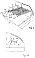
- the essential difference between the exemplary embodiment according to FIGS. 9 and 10 is that the first flat structure 23, which can be shifted into an approximately horizontal or alternatively into an approximately vertical protective position by the guide means analogously to the description of FIGS. 1 to 6, is another Fabric 22 is added.
- the fabric 22 can be pulled out parallel below the fabric 23 into an approximately horizontal protective position.
- the flexible sheet 22 is mounted on a winding shaft and can be unrolled, which is mounted parallel to a winding shaft 25 of the first sheet 23 below this winding shaft 25 in the cassette housing 21.
- the further flat structure 22 which is positioned below the first flat structure 23, has holding receptacles in a rear region of the loading space 20, in which a pull-out strip of the flat structure 22 can be temporarily fixed.
- the fabric 22 is opaque, whereas the first fabric 23 is designed as a translucent separating network.
- the further sheet 22 can be pulled out to provide additional privacy for objects located on the floor of the loading space.
- the further fabric 22 can also be pulled out when the first fabric 23 is in its approximately horizontal protective position. Because the surface structure 23 is only designed as a translucent network structure, in the horizontal protective position there is only a restraining function for objects located on the loading space floor, but not a privacy function.
- the additional surface structure 22 provides additional privacy.
- the further flat structure 22a is held on a winding shaft 24a, which is fastened to a tailgate 26 by means of corresponding holders or by means of a corresponding housing.
- the tailgate can be opened or closed in the direction of the double arrow in a generally known manner.
- suspension elements are provided for the pull-out strip of the further flat structure 22a.
- the flat structure 22a is designed to be opaque analogous to the flat structure 22, so that the same advantages result as in the case of an exemplary embodiment according to FIGS. 9 and 10.
- the length of the further flat structure 22a is preferably selected to be so large that the tailgate can be opened when the further flat structure 22a is pulled out, that is to say in the suspended state.
- the flat structure 22a then extends so far that it can join in with the opening movement of the tailgate 26 despite the suspended state.
- a corresponding return spring is assigned to the winding shaft 24a, which automatically causes the fabric 22a to be wound up and tensioned again when the tailgate is closed again.
Landscapes
- Engineering & Computer Science (AREA)
- Mechanical Engineering (AREA)
- Food Science & Technology (AREA)
- Vehicle Step Arrangements And Article Storage (AREA)
- Vehicle Interior And Exterior Ornaments, Soundproofing, And Insulation (AREA)
- Fittings On The Vehicle Exterior For Carrying Loads, And Devices For Holding Or Mounting Articles (AREA)
- Air Bags (AREA)
Applications Claiming Priority (2)
| Application Number | Priority Date | Filing Date | Title |
|---|---|---|---|
| DE10324289A DE10324289A1 (de) | 2003-05-21 | 2003-05-21 | Schutzvorrichtung für einen Innenraum eines Kraftfahrzeugs |
| DE10324289 | 2003-05-21 |
Publications (4)
| Publication Number | Publication Date |
|---|---|
| EP1479564A2 true EP1479564A2 (fr) | 2004-11-24 |
| EP1479564A3 EP1479564A3 (fr) | 2005-03-16 |
| EP1479564A8 EP1479564A8 (fr) | 2005-04-13 |
| EP1479564B1 EP1479564B1 (fr) | 2009-12-30 |
Family
ID=33039334
Family Applications (1)
| Application Number | Title | Priority Date | Filing Date |
|---|---|---|---|
| EP04010039A Expired - Lifetime EP1479564B1 (fr) | 2003-05-21 | 2004-04-28 | dispositif de protection pour intérieur véhicule |
Country Status (7)
| Country | Link |
|---|---|
| US (1) | US7055877B2 (fr) |
| EP (1) | EP1479564B1 (fr) |
| JP (1) | JP2004345633A (fr) |
| KR (1) | KR20040100970A (fr) |
| CN (1) | CN1572591A (fr) |
| AT (1) | ATE453544T1 (fr) |
| DE (2) | DE10324289A1 (fr) |
Cited By (8)
| Publication number | Priority date | Publication date | Assignee | Title |
|---|---|---|---|---|
| EP1498315A3 (fr) * | 2003-07-17 | 2005-06-01 | BOS GmbH & Co. KG | Dispositif fonctionnel pour le compartiment à bagages d'un véhicule |
| EP1775165A1 (fr) * | 2005-10-13 | 2007-04-18 | BOS GmbH & Co. KG | Cache-bagages d'un véhicule automobile |
| EP1787864A1 (fr) * | 2005-11-22 | 2007-05-23 | Mazda Motor Corporation | Structure arrière de véhicule |
| WO2007059943A1 (fr) * | 2005-11-22 | 2007-05-31 | Bayerische Motoren Werke Ag | Capot de coffre pour vehicule |
| EP1813475A1 (fr) * | 2006-01-30 | 2007-08-01 | Mazda Motor Corporation | Dispositif de recouvrement |
| FR2900611A1 (fr) * | 2006-05-05 | 2007-11-09 | Renault Sas | Dispositif cache bagages de longueur reglable pour coffre de vehicule automobile, et vehicule correspondant |
| DE102007005185B3 (de) * | 2007-01-29 | 2008-04-10 | Mp Solution Gmbh | Laderaumabdeckung |
| CN101011950B (zh) * | 2006-01-30 | 2011-01-05 | 马自达汽车株式会社 | 行李舱盖板装置 |
Families Citing this family (35)
| Publication number | Priority date | Publication date | Assignee | Title |
|---|---|---|---|---|
| DE10356911B3 (de) * | 2003-12-02 | 2005-01-20 | Bos Gmbh & Co. Kg | Laderaumschutzvorrichtung für ein Kraftfahrzeug |
| DE102004008874A1 (de) * | 2004-02-18 | 2005-09-08 | Bos Gmbh & Co. Kg | Funktionseinheit für einen Fahrzeuginnenraum |
| US7118152B2 (en) * | 2004-05-07 | 2006-10-10 | Ford Global Technologies, Llc | Automotive cargo restraint and security screen |
| DE502006000664D1 (de) * | 2005-03-02 | 2008-06-05 | Bos Gmbh | Laderaumabdeckung für ein Kraftfahrzeug |
| DE102005014798A1 (de) | 2005-03-31 | 2006-10-05 | Webasto Ag | Laderaumabdeckung für ein Fahrzeug |
| DE202005020665U1 (de) * | 2005-07-08 | 2006-05-18 | Bos Gmbh & Co. Kg | Laderaumschutzvorrichtung für ein Kraftfahrzeug |
| GB2431905A (en) * | 2005-11-01 | 2007-05-09 | Nissan Technical Ct Europ Ltd | Load space cover for vehicles |
| DE102005052618A1 (de) * | 2005-11-02 | 2007-05-03 | Bos Gmbh & Co. Kg | Heckfensterrollo ohne Restlichtspalt |
| JP4687547B2 (ja) * | 2006-04-18 | 2011-05-25 | マツダ株式会社 | 車両のトノカバー装置 |
| JP4687546B2 (ja) * | 2006-04-18 | 2011-05-25 | マツダ株式会社 | 車両のトノカバー装置 |
| DE102006005673B4 (de) * | 2006-02-01 | 2010-08-05 | Bos Gmbh & Co. Kg | Fahrzeugladeraum mit einer Laderaumabdeckung |
| DE102006015206B4 (de) * | 2006-03-30 | 2011-01-05 | Johnson Controls Gmbh | Vertikal verschiebbare Abdeckung des Laderaums |
| US20080042462A1 (en) * | 2006-08-18 | 2008-02-21 | Kevin Scotton | Collapsible tubing device for automobile shade |
| ATE505354T1 (de) * | 2006-09-27 | 2011-04-15 | Bos Gmbh | Manuell betätiges fensterrollo |
| KR100794025B1 (ko) * | 2006-12-15 | 2008-01-10 | 현대자동차주식회사 | 전후 이동이 가능한 컴비네이션 타입 카고 스크린 |
| JP4913616B2 (ja) * | 2007-01-30 | 2012-04-11 | 林テレンプ株式会社 | トノカバー装置 |
| JP5002297B2 (ja) * | 2007-03-28 | 2012-08-15 | 盟和産業株式会社 | ヒンジ機構及びそれを利用した自動車のラゲッジボード構造 |
| US20100301626A1 (en) * | 2007-04-25 | 2010-12-02 | Brentwood Prescott Reid | Cargo cage for an automobile |
| DE102007021428B4 (de) * | 2007-05-03 | 2012-08-30 | Bos Gmbh & Co. Kg | Abdeckungssystem für einen Heckstauraum eines Fahrzeugs |
| US20090033114A1 (en) * | 2007-08-02 | 2009-02-05 | Thomas Steigerwald | Loading area cover for a motor vehicle |
| JP4505496B2 (ja) * | 2007-12-11 | 2010-07-21 | 本田技研工業株式会社 | 車両用トノカバー装置 |
| JP5223417B2 (ja) * | 2008-03-31 | 2013-06-26 | マツダ株式会社 | 自動車のトノカバー装置 |
| DE102008051623A1 (de) | 2008-10-02 | 2010-04-08 | Dr. Ing. H.C. F. Porsche Aktiengesellschaft | Halteeinrichtung |
| US20110101736A1 (en) * | 2009-10-29 | 2011-05-05 | Mazda Motor Corporation | Rear structure for automobile |
| US20110126014A1 (en) * | 2009-11-24 | 2011-05-26 | Sony Ericsson Mobile Communications Ab | Event Triggered Pairing of Wireless Communication Devices Based on Time Measurements |
| FR2968252B1 (fr) * | 2010-12-07 | 2014-03-07 | Renault Sa | Tendelet repliable pour vehicule automobile |
| JP5607568B2 (ja) * | 2011-03-30 | 2014-10-15 | 株式会社東海理化電機製作所 | トノカバー装置 |
| JP5489359B2 (ja) * | 2011-07-25 | 2014-05-14 | トヨタ紡織株式会社 | パッケージトレイの支持構造 |
| JP6266446B2 (ja) * | 2014-06-23 | 2018-01-24 | 本田技研工業株式会社 | トノカバー装置 |
| US9527451B2 (en) * | 2015-05-08 | 2016-12-27 | Ford Global Technologies, Llc | Retractable cargo cover with integral storage compartment |
| JP6485219B2 (ja) * | 2015-05-26 | 2019-03-20 | トヨタ紡織株式会社 | 車両用トノカバー装置 |
| DE102016116775C5 (de) * | 2016-09-07 | 2023-07-13 | Macauto Industrial Co., Ltd. | Laderaumtrennnetz mit Auszugsbegrenzung |
| US10611314B2 (en) * | 2017-09-29 | 2020-04-07 | Faurecia Automotive Seating, Llc | Vehicle privacy screen |
| KR102739204B1 (ko) * | 2018-12-14 | 2024-12-05 | 현대자동차주식회사 | 차량의 카고 스크린 어셈블리 |
| DE102024105285A1 (de) | 2023-03-07 | 2024-09-12 | Bos Gmbh & Co. Kg | Schutzvorrichtung für einen Fahrzeuginnenraum |
Family Cites Families (11)
| Publication number | Priority date | Publication date | Assignee | Title |
|---|---|---|---|---|
| US4252362A (en) * | 1979-10-09 | 1981-02-24 | Campbell John T | Pickup bed cover |
| DE3630195A1 (de) * | 1986-09-04 | 1988-03-10 | Eugen Seitz | Rollo fuer das heckabteil eines kombifahrzeuges |
| US5711568A (en) * | 1996-02-05 | 1998-01-27 | Diem; D.W. | Retractable cargo cover |
| DE19722501B4 (de) * | 1996-06-08 | 2011-01-27 | Volkswagen Ag | Vorrichtung zur Ladegutsicherung an einem Fahrzeug |
| FR2755655B1 (fr) * | 1996-11-08 | 1998-12-04 | Peugeot | Dispositif de retenue d'objets sur un plancher de vehicule |
| DE19650775C2 (de) * | 1996-12-06 | 1999-03-11 | Baumeister & Ostler Gmbh Co | Abdeckrollo mit vereinfachter Bedienung |
| DE19833571C1 (de) * | 1998-07-27 | 1999-12-02 | Peter Butz Gmbh Verwaltungs Kg | Rückhaltevorrichtung zur Abtrennung eines Laderaums eines Fahrzeugs, z. B. eines Kombinations-Kraftwagens, einer Großraumlimousine o. dgl. |
| DE19906648B4 (de) * | 1999-02-18 | 2014-04-17 | Bayerische Motoren Werke Aktiengesellschaft | Vorrichtung zur Führung eines Ladebodens in einem Gepäckraum eines Personenkraftfahrzeugs |
| DE19944948C1 (de) * | 1999-09-20 | 2001-05-31 | Baumeister & Ostler Gmbh Co | Schutzvorrichtung für einen Innenraum eines Kraftfahrzeuges |
| DE10102792A1 (de) * | 2001-01-22 | 2002-08-01 | Webasto Vehicle Sys Int Gmbh | Laderaumabdeckung für Personenkraftfahrzeuge |
| DE10323605B4 (de) * | 2003-05-20 | 2007-03-01 | Bos Gmbh & Co. Kg | Schutzvorrichtung für einen Laderaum eines Kraftfahrzeuges |
-
2003
- 2003-05-21 DE DE10324289A patent/DE10324289A1/de not_active Withdrawn
-
2004
- 2004-04-28 EP EP04010039A patent/EP1479564B1/fr not_active Expired - Lifetime
- 2004-04-28 AT AT04010039T patent/ATE453544T1/de not_active IP Right Cessation
- 2004-04-28 DE DE502004010572T patent/DE502004010572D1/de not_active Expired - Lifetime
- 2004-05-19 KR KR1020040035432A patent/KR20040100970A/ko not_active Withdrawn
- 2004-05-19 JP JP2004149201A patent/JP2004345633A/ja active Pending
- 2004-05-20 US US10/850,560 patent/US7055877B2/en not_active Expired - Fee Related
- 2004-05-21 CN CNA2004100475168A patent/CN1572591A/zh active Pending
Cited By (13)
| Publication number | Priority date | Publication date | Assignee | Title |
|---|---|---|---|---|
| EP1498315A3 (fr) * | 2003-07-17 | 2005-06-01 | BOS GmbH & Co. KG | Dispositif fonctionnel pour le compartiment à bagages d'un véhicule |
| US7052063B2 (en) | 2003-07-17 | 2006-05-30 | Bos Gmbh & Co. Kg | Functional device for a motor vehicle loading area |
| EP1775165A1 (fr) * | 2005-10-13 | 2007-04-18 | BOS GmbH & Co. KG | Cache-bagages d'un véhicule automobile |
| US7537265B2 (en) | 2005-11-22 | 2009-05-26 | Mazda Motor Corporation | Vehicle rear structure |
| WO2007059943A1 (fr) * | 2005-11-22 | 2007-05-31 | Bayerische Motoren Werke Ag | Capot de coffre pour vehicule |
| EP1787864A1 (fr) * | 2005-11-22 | 2007-05-23 | Mazda Motor Corporation | Structure arrière de véhicule |
| DE102005055625C5 (de) * | 2005-11-22 | 2010-05-20 | Bayerische Motoren Werke Aktiengesellschaft | Laderaumabdeckung für ein Fahrzeug |
| EP1813475A1 (fr) * | 2006-01-30 | 2007-08-01 | Mazda Motor Corporation | Dispositif de recouvrement |
| US7641256B2 (en) | 2006-01-30 | 2010-01-05 | Mazda Motor Corporation | Tonneau cover device |
| CN101011950B (zh) * | 2006-01-30 | 2011-01-05 | 马自达汽车株式会社 | 行李舱盖板装置 |
| FR2900611A1 (fr) * | 2006-05-05 | 2007-11-09 | Renault Sas | Dispositif cache bagages de longueur reglable pour coffre de vehicule automobile, et vehicule correspondant |
| WO2007128936A1 (fr) * | 2006-05-05 | 2007-11-15 | Renault S.A.S. | Dispositif cache bagages de longueur reglable pour coffre de vehicule automobile et vehicule correspondant |
| DE102007005185B3 (de) * | 2007-01-29 | 2008-04-10 | Mp Solution Gmbh | Laderaumabdeckung |
Also Published As
| Publication number | Publication date |
|---|---|
| JP2004345633A (ja) | 2004-12-09 |
| EP1479564B1 (fr) | 2009-12-30 |
| CN1572591A (zh) | 2005-02-02 |
| DE10324289A1 (de) | 2004-12-23 |
| US7055877B2 (en) | 2006-06-06 |
| EP1479564A3 (fr) | 2005-03-16 |
| DE502004010572D1 (de) | 2010-02-11 |
| KR20040100970A (ko) | 2004-12-02 |
| EP1479564A8 (fr) | 2005-04-13 |
| ATE453544T1 (de) | 2010-01-15 |
| US20050012352A1 (en) | 2005-01-20 |
Similar Documents
| Publication | Publication Date | Title |
|---|---|---|
| EP1479564A2 (fr) | dispositif de protection pour intérieur véhicule | |
| EP1283130B1 (fr) | Dispositif de protection pour le compartiment bagages d'un véhicule | |
| DE10348892B4 (de) | Schutzvorrichtung für einen Laderaum eines Kraftfahrzeugs | |
| DE102008020528A1 (de) | Kraftfahrzeug mit einer Sonnenblendschutzeinrichtung für die Fensterscheibe | |
| EP1800922B1 (fr) | Store à enrouler pour ombrage total d'une vitre arrière | |
| DE4124449A1 (de) | Modulares gepaecksicherungssystem | |
| EP1065109A2 (fr) | Cloisonnement pour coffre de véhicule | |
| DE10320108B4 (de) | Kraftfahrzeug mit einer Abschottungseinrichtung | |
| EP1986876B1 (fr) | Dispositif d'obscurcissement pour une vitre transparente, notamment pour vehicules automobiles | |
| DE19806736C2 (de) | Schutzvorrichtung für eine Scheibe eines Kraftfahrzeugs | |
| DE19930049C2 (de) | Eine oberhalb des Windschutzscheibenrahmens von Personenkraftwagen angeordnete Abschirmvorrichtung | |
| DE19602598C1 (de) | Offener Personenkraftwagen | |
| DE10307212B4 (de) | Laderaumabdeckung mit zusätzlichem Rollo | |
| DE102005021399B4 (de) | Rollo für Fahrzeugfenster | |
| EP1892136B1 (fr) | Cabriolet doté de deux arceaux de sécurité mutuellement opposés et d'un pare-vent | |
| DE602005001587T2 (de) | Rollo für Gepäckraumabdeckung für ein Kraftfahrzeug und hiermit ausgestattetes Fahrzeug | |
| EP1382489A1 (fr) | Dispositif de protection pour le coffre d'un véhicule | |
| EP2922728A1 (fr) | Dispositif de protection destiné à l'habitacle d'un véhicule et mécanisme de levage pour ledit dispositif | |
| DE10203877B4 (de) | Fahrzeugdach mit seitwärts öffnenden Dachelementen | |
| DE102010056233A1 (de) | Rollo-Windschott für ein Cabrio-Fahrzeug | |
| EP1736342B1 (fr) | Déflecteur de vent pour un cabriolet et cabriolet avec un déflecteur de vent | |
| DE20019704U1 (de) | Laderaum-Abdeck- und/oder Laderaum-Trennvorrichtung für den Lade- oder Gepäckraum eines Fahrzeuges | |
| DE102017206905B4 (de) | Gepäckraumabdeckung und Abtrenneinrichtung | |
| DE102014010887A1 (de) | Rollo für ein Fahrzeug, insbesondere einen Personenkraftwagen | |
| DE19736838B4 (de) | Rolloanordnung zwischen einem Laderaum und einem Fahrgastraum eines Kraftfahrzeugs |
Legal Events
| Date | Code | Title | Description |
|---|---|---|---|
| PUAI | Public reference made under article 153(3) epc to a published international application that has entered the european phase |
Free format text: ORIGINAL CODE: 0009012 |
|
| AK | Designated contracting states |
Kind code of ref document: A2 Designated state(s): AT BE BG CH CY CZ DE DK EE ES FI FR GB GR HU IE IT LI LU MC NL PL PT RO SE SI SK TR |
|
| AX | Request for extension of the european patent |
Extension state: AL HR LT LV MK |
|
| PUAL | Search report despatched |
Free format text: ORIGINAL CODE: 0009013 |
|
| RIN1 | Information on inventor provided before grant (corrected) |
Inventor name: SPARRER, HENNING Inventor name: LECHNER, MATTHIAS, DR. Inventor name: SEEG, THOMAS Inventor name: STOECKL, SIEGFRIED |
|
| AK | Designated contracting states |
Kind code of ref document: A3 Designated state(s): AT BE BG CH CY CZ DE DK EE ES FI FR GB GR HU IE IT LI LU MC NL PL PT RO SE SI SK TR |
|
| AX | Request for extension of the european patent |
Extension state: AL HR LT LV MK |
|
| 17P | Request for examination filed |
Effective date: 20050510 |
|
| RIN1 | Information on inventor provided before grant (corrected) |
Inventor name: SPARRER, HENNING Inventor name: STOECKL, SIEGFRIED Inventor name: LECHNER, MATTHIAS, DR. Inventor name: SEEG, THOMAS |
|
| AKX | Designation fees paid |
Designated state(s): AT BE BG CH CY CZ DE DK EE ES FI FR GB GR HU IE IT LI LU MC NL PL PT RO SE SI SK TR |
|
| APBN | Date of receipt of notice of appeal recorded |
Free format text: ORIGINAL CODE: EPIDOSNNOA2E |
|
| APBR | Date of receipt of statement of grounds of appeal recorded |
Free format text: ORIGINAL CODE: EPIDOSNNOA3E |
|
| APAF | Appeal reference modified |
Free format text: ORIGINAL CODE: EPIDOSCREFNE |
|
| APBT | Appeal procedure closed |
Free format text: ORIGINAL CODE: EPIDOSNNOA9E |
|
| GRAP | Despatch of communication of intention to grant a patent |
Free format text: ORIGINAL CODE: EPIDOSNIGR1 |
|
| GRAS | Grant fee paid |
Free format text: ORIGINAL CODE: EPIDOSNIGR3 |
|
| GRAA | (expected) grant |
Free format text: ORIGINAL CODE: 0009210 |
|
| AK | Designated contracting states |
Kind code of ref document: B1 Designated state(s): AT BE BG CH CY CZ DE DK EE ES FI FR GB GR HU IE IT LI LU MC NL PL PT RO SE SI SK TR |
|
| REG | Reference to a national code |
Ref country code: GB Ref legal event code: FG4D Free format text: NOT ENGLISH |
|
| REG | Reference to a national code |
Ref country code: CH Ref legal event code: EP |
|
| REG | Reference to a national code |
Ref country code: IE Ref legal event code: FG4D |
|
| REF | Corresponds to: |
Ref document number: 502004010572 Country of ref document: DE Date of ref document: 20100211 Kind code of ref document: P |
|
| PG25 | Lapsed in a contracting state [announced via postgrant information from national office to epo] |
Ref country code: FI Free format text: LAPSE BECAUSE OF FAILURE TO SUBMIT A TRANSLATION OF THE DESCRIPTION OR TO PAY THE FEE WITHIN THE PRESCRIBED TIME-LIMIT Effective date: 20091230 Ref country code: SE Free format text: LAPSE BECAUSE OF FAILURE TO SUBMIT A TRANSLATION OF THE DESCRIPTION OR TO PAY THE FEE WITHIN THE PRESCRIBED TIME-LIMIT Effective date: 20091230 |
|
| REG | Reference to a national code |
Ref country code: NL Ref legal event code: VDEP Effective date: 20091230 |
|
| PG25 | Lapsed in a contracting state [announced via postgrant information from national office to epo] |
Ref country code: PL Free format text: LAPSE BECAUSE OF FAILURE TO SUBMIT A TRANSLATION OF THE DESCRIPTION OR TO PAY THE FEE WITHIN THE PRESCRIBED TIME-LIMIT Effective date: 20091230 Ref country code: SI Free format text: LAPSE BECAUSE OF FAILURE TO SUBMIT A TRANSLATION OF THE DESCRIPTION OR TO PAY THE FEE WITHIN THE PRESCRIBED TIME-LIMIT Effective date: 20091230 |
|
| REG | Reference to a national code |
Ref country code: IE Ref legal event code: FD4D |
|
| PG25 | Lapsed in a contracting state [announced via postgrant information from national office to epo] |
Ref country code: NL Free format text: LAPSE BECAUSE OF FAILURE TO SUBMIT A TRANSLATION OF THE DESCRIPTION OR TO PAY THE FEE WITHIN THE PRESCRIBED TIME-LIMIT Effective date: 20091230 Ref country code: PT Free format text: LAPSE BECAUSE OF FAILURE TO SUBMIT A TRANSLATION OF THE DESCRIPTION OR TO PAY THE FEE WITHIN THE PRESCRIBED TIME-LIMIT Effective date: 20100430 Ref country code: ES Free format text: LAPSE BECAUSE OF FAILURE TO SUBMIT A TRANSLATION OF THE DESCRIPTION OR TO PAY THE FEE WITHIN THE PRESCRIBED TIME-LIMIT Effective date: 20100410 Ref country code: RO Free format text: LAPSE BECAUSE OF FAILURE TO SUBMIT A TRANSLATION OF THE DESCRIPTION OR TO PAY THE FEE WITHIN THE PRESCRIBED TIME-LIMIT Effective date: 20091230 Ref country code: BG Free format text: LAPSE BECAUSE OF FAILURE TO SUBMIT A TRANSLATION OF THE DESCRIPTION OR TO PAY THE FEE WITHIN THE PRESCRIBED TIME-LIMIT Effective date: 20100330 Ref country code: EE Free format text: LAPSE BECAUSE OF FAILURE TO SUBMIT A TRANSLATION OF THE DESCRIPTION OR TO PAY THE FEE WITHIN THE PRESCRIBED TIME-LIMIT Effective date: 20091230 |
|
| PG25 | Lapsed in a contracting state [announced via postgrant information from national office to epo] |
Ref country code: CZ Free format text: LAPSE BECAUSE OF FAILURE TO SUBMIT A TRANSLATION OF THE DESCRIPTION OR TO PAY THE FEE WITHIN THE PRESCRIBED TIME-LIMIT Effective date: 20091230 Ref country code: SK Free format text: LAPSE BECAUSE OF FAILURE TO SUBMIT A TRANSLATION OF THE DESCRIPTION OR TO PAY THE FEE WITHIN THE PRESCRIBED TIME-LIMIT Effective date: 20091230 |
|
| PG25 | Lapsed in a contracting state [announced via postgrant information from national office to epo] |
Ref country code: IE Free format text: LAPSE BECAUSE OF FAILURE TO SUBMIT A TRANSLATION OF THE DESCRIPTION OR TO PAY THE FEE WITHIN THE PRESCRIBED TIME-LIMIT Effective date: 20091230 Ref country code: CY Free format text: LAPSE BECAUSE OF FAILURE TO SUBMIT A TRANSLATION OF THE DESCRIPTION OR TO PAY THE FEE WITHIN THE PRESCRIBED TIME-LIMIT Effective date: 20091230 Ref country code: GR Free format text: LAPSE BECAUSE OF FAILURE TO SUBMIT A TRANSLATION OF THE DESCRIPTION OR TO PAY THE FEE WITHIN THE PRESCRIBED TIME-LIMIT Effective date: 20100331 |
|
| BERE | Be: lapsed |
Owner name: BOS G.M.B.H. & CO. KG Effective date: 20100430 |
|
| PLBE | No opposition filed within time limit |
Free format text: ORIGINAL CODE: 0009261 |
|
| STAA | Information on the status of an ep patent application or granted ep patent |
Free format text: STATUS: NO OPPOSITION FILED WITHIN TIME LIMIT |
|
| PG25 | Lapsed in a contracting state [announced via postgrant information from national office to epo] |
Ref country code: MC Free format text: LAPSE BECAUSE OF NON-PAYMENT OF DUE FEES Effective date: 20100430 |
|
| REG | Reference to a national code |
Ref country code: CH Ref legal event code: PL |
|
| 26N | No opposition filed |
Effective date: 20101001 |
|
| GBPC | Gb: european patent ceased through non-payment of renewal fee |
Effective date: 20100428 |
|
| REG | Reference to a national code |
Ref country code: FR Ref legal event code: ST Effective date: 20101230 |
|
| PG25 | Lapsed in a contracting state [announced via postgrant information from national office to epo] |
Ref country code: DK Free format text: LAPSE BECAUSE OF FAILURE TO SUBMIT A TRANSLATION OF THE DESCRIPTION OR TO PAY THE FEE WITHIN THE PRESCRIBED TIME-LIMIT Effective date: 20091230 |
|
| PG25 | Lapsed in a contracting state [announced via postgrant information from national office to epo] |
Ref country code: LI Free format text: LAPSE BECAUSE OF NON-PAYMENT OF DUE FEES Effective date: 20100430 Ref country code: CH Free format text: LAPSE BECAUSE OF NON-PAYMENT OF DUE FEES Effective date: 20100430 |
|
| PG25 | Lapsed in a contracting state [announced via postgrant information from national office to epo] |
Ref country code: IT Free format text: LAPSE BECAUSE OF FAILURE TO SUBMIT A TRANSLATION OF THE DESCRIPTION OR TO PAY THE FEE WITHIN THE PRESCRIBED TIME-LIMIT Effective date: 20091230 Ref country code: GB Free format text: LAPSE BECAUSE OF NON-PAYMENT OF DUE FEES Effective date: 20100428 Ref country code: BE Free format text: LAPSE BECAUSE OF NON-PAYMENT OF DUE FEES Effective date: 20100430 |
|
| PG25 | Lapsed in a contracting state [announced via postgrant information from national office to epo] |
Ref country code: AT Free format text: LAPSE BECAUSE OF NON-PAYMENT OF DUE FEES Effective date: 20100428 |
|
| PG25 | Lapsed in a contracting state [announced via postgrant information from national office to epo] |
Ref country code: FR Free format text: LAPSE BECAUSE OF NON-PAYMENT OF DUE FEES Effective date: 20100430 |
|
| PG25 | Lapsed in a contracting state [announced via postgrant information from national office to epo] |
Ref country code: LU Free format text: LAPSE BECAUSE OF NON-PAYMENT OF DUE FEES Effective date: 20100428 Ref country code: HU Free format text: LAPSE BECAUSE OF FAILURE TO SUBMIT A TRANSLATION OF THE DESCRIPTION OR TO PAY THE FEE WITHIN THE PRESCRIBED TIME-LIMIT Effective date: 20100701 |
|
| PG25 | Lapsed in a contracting state [announced via postgrant information from national office to epo] |
Ref country code: TR Free format text: LAPSE BECAUSE OF FAILURE TO SUBMIT A TRANSLATION OF THE DESCRIPTION OR TO PAY THE FEE WITHIN THE PRESCRIBED TIME-LIMIT Effective date: 20091230 |
|
| REG | Reference to a national code |
Ref country code: DE Ref legal event code: R082 Ref document number: 502004010572 Country of ref document: DE |
|
| PGFP | Annual fee paid to national office [announced via postgrant information from national office to epo] |
Ref country code: DE Payment date: 20160427 Year of fee payment: 13 |
|
| REG | Reference to a national code |
Ref country code: DE Ref legal event code: R119 Ref document number: 502004010572 Country of ref document: DE |
|
| PG25 | Lapsed in a contracting state [announced via postgrant information from national office to epo] |
Ref country code: DE Free format text: LAPSE BECAUSE OF NON-PAYMENT OF DUE FEES Effective date: 20171103 |