EP1479582A1 - Hauptbremszylinder mit verkürztem Leerweg für eine Kraftfahrzeugbremsanlage - Google Patents
Hauptbremszylinder mit verkürztem Leerweg für eine Kraftfahrzeugbremsanlage Download PDFInfo
- Publication number
- EP1479582A1 EP1479582A1 EP04011702A EP04011702A EP1479582A1 EP 1479582 A1 EP1479582 A1 EP 1479582A1 EP 04011702 A EP04011702 A EP 04011702A EP 04011702 A EP04011702 A EP 04011702A EP 1479582 A1 EP1479582 A1 EP 1479582A1
- Authority
- EP
- European Patent Office
- Prior art keywords
- master cylinder
- lip
- chamber
- piston
- seal
- Prior art date
- Legal status (The legal status is an assumption and is not a legal conclusion. Google has not performed a legal analysis and makes no representation as to the accuracy of the status listed.)
- Granted
Links
- 238000003754 machining Methods 0.000 claims abstract description 17
- 230000000717 retained effect Effects 0.000 claims description 2
- 239000007788 liquid Substances 0.000 abstract description 11
- 230000010339 dilation Effects 0.000 abstract 1
- 239000012530 fluid Substances 0.000 description 19
- 238000007789 sealing Methods 0.000 description 5
- 208000031968 Cadaver Diseases 0.000 description 4
- 230000007423 decrease Effects 0.000 description 2
- 230000000994 depressogenic effect Effects 0.000 description 1
- 238000004519 manufacturing process Methods 0.000 description 1
- 238000000465 moulding Methods 0.000 description 1
- 230000003387 muscular Effects 0.000 description 1
- 230000035484 reaction time Effects 0.000 description 1
- 230000009257 reactivity Effects 0.000 description 1
- 230000000638 stimulation Effects 0.000 description 1
Images

Classifications
-
- B—PERFORMING OPERATIONS; TRANSPORTING
- B60—VEHICLES IN GENERAL
- B60T—VEHICLE BRAKE CONTROL SYSTEMS OR PARTS THEREOF; BRAKE CONTROL SYSTEMS OR PARTS THEREOF, IN GENERAL; ARRANGEMENT OF BRAKING ELEMENTS ON VEHICLES IN GENERAL; PORTABLE DEVICES FOR PREVENTING UNWANTED MOVEMENT OF VEHICLES; VEHICLE MODIFICATIONS TO FACILITATE COOLING OF BRAKES
- B60T11/00—Transmitting braking action from initiating means to ultimate brake actuator without power assistance or drive or where such assistance or drive is irrelevant
- B60T11/10—Transmitting braking action from initiating means to ultimate brake actuator without power assistance or drive or where such assistance or drive is irrelevant transmitting by fluid means, e.g. hydraulic
- B60T11/16—Master control, e.g. master cylinders
- B60T11/232—Recuperation valves
-
- B—PERFORMING OPERATIONS; TRANSPORTING
- B60—VEHICLES IN GENERAL
- B60T—VEHICLE BRAKE CONTROL SYSTEMS OR PARTS THEREOF; BRAKE CONTROL SYSTEMS OR PARTS THEREOF, IN GENERAL; ARRANGEMENT OF BRAKING ELEMENTS ON VEHICLES IN GENERAL; PORTABLE DEVICES FOR PREVENTING UNWANTED MOVEMENT OF VEHICLES; VEHICLE MODIFICATIONS TO FACILITATE COOLING OF BRAKES
- B60T11/00—Transmitting braking action from initiating means to ultimate brake actuator without power assistance or drive or where such assistance or drive is irrelevant
- B60T11/10—Transmitting braking action from initiating means to ultimate brake actuator without power assistance or drive or where such assistance or drive is irrelevant transmitting by fluid means, e.g. hydraulic
- B60T11/16—Master control, e.g. master cylinders
- B60T11/224—Master control, e.g. master cylinders with pressure-varying means, e.g. with two stage operation provided by use of different piston diameters including continuous variation from one diameter to another
-
- B—PERFORMING OPERATIONS; TRANSPORTING
- B60—VEHICLES IN GENERAL
- B60T—VEHICLE BRAKE CONTROL SYSTEMS OR PARTS THEREOF; BRAKE CONTROL SYSTEMS OR PARTS THEREOF, IN GENERAL; ARRANGEMENT OF BRAKING ELEMENTS ON VEHICLES IN GENERAL; PORTABLE DEVICES FOR PREVENTING UNWANTED MOVEMENT OF VEHICLES; VEHICLE MODIFICATIONS TO FACILITATE COOLING OF BRAKES
- B60T11/00—Transmitting braking action from initiating means to ultimate brake actuator without power assistance or drive or where such assistance or drive is irrelevant
- B60T11/10—Transmitting braking action from initiating means to ultimate brake actuator without power assistance or drive or where such assistance or drive is irrelevant transmitting by fluid means, e.g. hydraulic
- B60T11/16—Master control, e.g. master cylinders
- B60T11/236—Piston sealing arrangements
Definitions
- the present invention relates to a master cylinder for a motor vehicle braking system. More specifically the invention concerns the dead stroke of a piston in a master cylinder. The invention has intended to reduce the dead travel in a master cylinder during a braking. Its additional purpose is to facilitate the readmission of fluid in a master cylinder room.
- braking systems are fitted with a master cylinder.
- a driver presses on a control device, for example a brake pedal, which activates the master cylinder. It is possible to insert between the brake pedal and the master cylinder a servomotor.
- the servomotor increases the effort exerted on the brake pedal and transmitted to the master cylinder.
- a master cylinder has a shaped master cylinder body general cylindrical.
- the body of the master cylinder is hollow.
- Inside of master cylinder body slide a primary piston and a piston secondary.
- the primary piston is in support, via a spring primary, against the secondary piston while the secondary piston comes in support, by means of a secondary spring, against a bottom of the body of master cylinder.
- a primary chamber is provided between the primary piston and the secondary piston.
- the primary chamber contains the primary spring.
- a secondary chamber is provided between the bottom of the master cylinder and the secondary piston.
- the secondary chamber contains the secondary spring.
- a hydraulic fluid tank is fixed on the master cylinder.
- the reservoir communicates with each chamber of the master cylinder by a channel tank connection.
- a seal in the form of cup.
- the seal is arranged in a circular bore formed in a groove at inside the body of the master cylinder.
- the bore is open towards the light of the master cylinder.
- the joint is fixed.
- An internal lip of the seal i.e. that located on the light side of the master cylinder, is slightly shorter than an outer lip.
- the outer lip is located against a wall circumferential of the bore.
- a base connects the two lips. The base is in support against a radial wall of the bore.
- a dilatation opening, and more generally compensating for leaks, is formed in a skirt of the piston.
- the expansion In the rest position, the expansion is opposite a tank connection channel. It allows the passage of liquid from the reservoir to the corresponding chamber of the master cylinder.
- the advance of the piston of the master cylinder, and therefore of its skirt, drives the expansion hole in the direction of a master cylinder bottom.
- the expansion orifice is then closed by the internal lip of the seal. Bedroom is thus hermetically closed on the side of the expansion orifice.
- the liquid can no longer escape through the tank connection channel. Pressure in the master cylinder chamber then goes up. If the action on a pedal is exercised further, the liquid is injected towards the brakes by a channel of connection.
- dead stroke it is therefore necessary for the piston to travel a certain distance, called dead stroke, before the pressure builds up in the master cylinder.
- This dead stroke is proportional to part of the movement of the brake pedal, during which no braking takes place. We understand the need to minimize this dead race.
- the dead race is the distance travels before mounting pressure in the master cylinder. So this is the distance from one edge of the expansion opening to the internal lip of the joint when the orifice is sealed.
- the race dead is large, due to the distance traveled by the piston to seal sealing the pressure chamber.
- This race is important from made it necessary to have a sufficiently large passage section between the tank and the brakes, due to the presence of electronic trajectory control (ESP).
- ESP electronic trajectory control
- a master cylinder with an expansion hole and a valve.
- the valve is placed in a base of a piston, bearing against a pin.
- the pin is perpendicular to a longitudinal axis of the master cylinder.
- the pin is in a housing provided in the body of the master cylinder. At rest the valve is open.
- the valve section is such hydraulic fluid can flow from the fluid reservoir hydraulic to the master cylinder chamber through the pin and valve housings.
- a spring of valve compresses and the brake fluid is replenished through the orifice supply and by the valve.
- ABS anti-blocking systems
- a master cylinder chamber is provided with a valve, while another chamber is provided with a seal. Most often a room primary has the seal while a secondary chamber is fitted with a valve. Indeed, the secondary bedroom is often the first to build up pressure. Generally the pressure rise in the chamber secondary is enough to brake a vehicle.
- the invention provides a master cylinder which does not have the disadvantages above. Its purpose is to provide a master cylinder whose dead stroke is short and rapid re-admission of fluid.
- an opening is made in the body of the master cylinder. This hole allows additional communication between the tank and a master cylinder chamber. It is through this opening that readmits hydraulic fluid.
- the seal is positioned in the body of the master. cylinder near an expansion hole. Due to the short distance that must travel through a piston fitted with the expansion opening so that it is closed by the joint, the dead stroke is short.
- the groove which receives the U-shaped joint can have a volume greater than the size of the joint itself. So a space is formed between a free end of the outer lip and a radial wall of the throat.
- One end of the internal lip of the seal is preferably attached to an edge of the dilatation opening.
- the expansion hole is thus closed very quickly by the internal lip.
- the dead race is therefore very scaled down.
- the pressure in the corresponding chamber therefore follows almost immediate stimulation of a brake pedal by a driver.
- Figure 1 shows a master cylinder 1 with a lip seal 16 and 17 seal having a U-shaped section.
- the master cylinder 1 is provided with a body 2 of master cylinder of axis X.
- Body 2 of master cylinder is pierced with a longitudinal bore of axis X.
- a reservoir (not shown) is fixed on the master cylinder 1.
- a primary piston 3 slides in the master bore cylinder 1 in the direction of a secondary piston 4.
- a primary chamber 5 is delimited by the primary piston 3 and the secondary piston 4.
- a chamber secondary 6 is delimited by the secondary piston 4 and a bottom 7 of the master cylinder.
- the master cylinder 1 comprises, for example, on an upper part two taps.
- the tank is fixed to the master cylinder 1 by extensions tubular formed on the tank and introduced into the nozzles.
- a connection therefore the hydraulic tank, communicates with the chamber secondary 6 via a connection channel 10 and an orifice supply 11.
- Another connection communicates with the primary chamber 5 via a connection channel 12 and an orifice 13.
- the tank can be fixed to the master cylinder by any other known means, such as screwing, clipping ...
- the primary piston 3 comprises a skirt, provided with an orifice 14 named primary expansion hole.
- a skirt of the secondary piston is also provided with an orifice 15 for expansion.
- the position of the primary pistons and secondary is such that the expansion ports 14 and 15 are open. They communicate respectively with the supply orifices 11 and 13, and with primary 5 and secondary 6 chambers.
- Chambers 5 and 6 of the master cylinder 1 are then isolated from atmospheric pressure.
- the volume of rooms 5 and 6 decreases as the corresponding pistons 3 and 4 advance to inside the body 2.
- the pressure in the chambers increases.
- the means seal is formed by a seal 16, 17 with a U-shaped seal lip.
- This seal 16, 17 is housed in the body 2 of the master cylinder, in a groove in the wall of the bore.
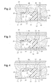
- FIG. 2 3 and 4 is shown an enlargement of a joint sealing 20 in a groove 21 according to the invention.
- the seal 20 can be located in a groove 21 at the level of the primary chamber 5 and or secondary 6.
- the seal 20 is the same as the seals 16 and 17 in FIG. 1.
- An expansion orifice 30 is formed on a skirt of a piston 31, equivalent to the orifices 14 and 15 of the pistons 3 and 4 of FIG. 1.
- the seal 20 is provided with an internal lip 22 and an external lip 23.
- internal means the bore side of the master cylinder, and by external side master cylinder body.
- a base 24 connects the internal lip 22 to the lip external 23.
- the external lip 23 rests against a wall of the groove 21.
- the outer lip bears against a circumferential wall of the body 2.
- the internal lip 22 is preferably shorter than the lip external 23.
- the groove 21 has a volume greater than the size of the seal 20 to U-shaped section. A space 25 is thus provided between a free end 26 of the outer lip 23 and a radial wall 27 of the groove 21.
- a machining hole 28 allows communication between the groove 21 and the hydraulic tank via a connection channel 29.
- the lip outer 23 is located against the machining hole 28.
- the machining hole 28 is not not sealed.
- a supply port 34 is open. Hydraulic fluid can in particular pass into the master cylinder 5 and 6 via the machining hole 28.
- the groove 21 is filled with hydraulic fluid, which can escape to the master cylinder through the expansion opening 30.
- FIG. 3 is shown the same enlargement as in the Figure 2.
- the piston 31 has slipped inside the body 2 of master cylinder 1.
- the expansion orifice 30 is closed on the body side of the master cylinder by one face internal of the internal lip 22 of the seal 20.
- the supply port 34 is also closed by the advance of the piston. Hydraulic fluid does not can no longer enter the pressure chamber.
- the volume of the room, due to the advance of the master cylinder piston, decreases.
- the pressure to the interior of the master cylinder chamber increases.
- the outer lip 23 is pressed against the machining hole 28.
- the machining hole 28 is thus closed tightly by the lip 23. No liquid coming from the channel 29 of tank connection cannot enter the groove 21.
- a flange 32 of the expansion orifice 30 is very close to a end 33 of the base 24 carrying the internal lip 22.
- the end 33 is in the extension of the rim 32.
- the lip 22 can be small and rigid.
- the dead run which is here represented by the distance from the edge 32 of the orifice 30 up to the lip 22 when the orifice is sealed, is very short. This is in particular allowed by the fact that the internal lip is rigid and short.
- the length of the inner lip was one length greater than that of the invention. Indeed in the state of the art, this internal lip must also allow the re-admission of hydraulic fluid. It must be of sufficient length, so as not to be sucked in by the dilatation orifice during the depression which takes place when the foot pedal brake is released.
- the master cylinder chamber does not cannot readmit liquid.
- a very close second braking does not give satisfaction. Indeed all the liquid went to brake pads and the re-admission of hydraulic fluid between the two brakes is not sufficient.
- the brake pedal is depressed without the possibility of braking correct the second time.
- the external lip 23 is flexible. So it easily lifts when the pressure builds up, and takes off during the depression phase.
- a U-shaped seal in accordance with the invention is obtained especially by molding.
- the seal can be rubber.
- the machining hole 28 has a 0.5 to 0.9 mm in diameter, for example 0.7 mm.
- Joint dimensions sealing 20 are 4 to 5 mm by 3 to 3.5 mm, for example 4.5 mm by 3.2 mm.
- the space 25 between the free end 26 of the outer lip 23 and the radial face of the groove is 0.2 to 0.7 mm, for example 0.5 mm.
- Most small distance between the inner lip 22 and the outer lip 23 is included between 0.5 and 1 mm, for example 0.8 mm.
- boss 32 forming a notch.
- Such boss 32 prevents the seal 20 from advancing in the groove 21.
- the groove 21 being larger than seal 20, it is necessary that seal 20 be fixed and does not move.
- the boss 32 is retained in a notch formed in the body 2 of the master cylinder 1.
- the notch extends the groove 21 at an upper wall.
- the boss 32 is formed on an outer wall of base 20.
- the notch can also be formed in a radial wall of the throat.
- the secondary chamber is the first to increase in pressure. So we can preferably provide the secondary chamber with a seal and a machining hole of the invention, in order to have a reduced dead travel and to build up pressure as quickly as possible.
- the primary chamber can be fitted with a conventional gasket or a valve system such as described in the state of the art.
- the invention also applies in the case of a master cylinder provided a single chamber and a single piston.
Landscapes
- Engineering & Computer Science (AREA)
- Transportation (AREA)
- Mechanical Engineering (AREA)
- Transmission Of Braking Force In Braking Systems (AREA)
- Braking Systems And Boosters (AREA)
- Braking Arrangements (AREA)
Applications Claiming Priority (2)
| Application Number | Priority Date | Filing Date | Title |
|---|---|---|---|
| FR0306367A FR2855132B1 (fr) | 2003-05-22 | 2003-05-22 | Maitre-cylindre pour systeme de freinage de vehicule automobile avec course morte reduite |
| FR0306367 | 2003-05-22 |
Publications (2)
| Publication Number | Publication Date |
|---|---|
| EP1479582A1 true EP1479582A1 (de) | 2004-11-24 |
| EP1479582B1 EP1479582B1 (de) | 2011-04-06 |
Family
ID=33042033
Family Applications (1)
| Application Number | Title | Priority Date | Filing Date |
|---|---|---|---|
| EP04011702A Expired - Lifetime EP1479582B1 (de) | 2003-05-22 | 2004-05-17 | Hauptbremszylinder mit verkürztem Leerweg für eine Kraftfahrzeugbremsanlage |
Country Status (4)
| Country | Link |
|---|---|
| EP (1) | EP1479582B1 (de) |
| AT (1) | ATE504477T1 (de) |
| DE (1) | DE602004032086D1 (de) |
| FR (1) | FR2855132B1 (de) |
Cited By (6)
| Publication number | Priority date | Publication date | Assignee | Title |
|---|---|---|---|---|
| DE102005043975A1 (de) * | 2005-09-15 | 2007-03-22 | Continental Teves Ag & Co. Ohg | Kolben mit einer gefesselten Feder |
| FR2904959A1 (fr) * | 2006-08-18 | 2008-02-22 | Bosch Gmbh Robert | Maitre-cylindre de frein a course morte reduite |
| EP1995138A1 (de) * | 2007-05-21 | 2008-11-26 | Robert Bosch GmbH | Hauptbremszylinder, der eine Fuge zum leichteren Nachfüllen der Bremse umfasst |
| EP1995139A1 (de) * | 2007-05-22 | 2008-11-26 | Robert Bosch GmbH | Hauptbremszylinder, der eine Fuge und eine entsprechende Hohlkehle zum leichteren Nachfüllen der Bremse umfasst |
| CN112810592A (zh) * | 2021-03-05 | 2021-05-18 | 江苏沃得农业机械股份有限公司 | 一种双路二级压力增压制动泵 |
| CN115782842A (zh) * | 2022-12-05 | 2023-03-14 | 浙江安统汽车部件有限公司 | 一种制动主缸总成 |
Citations (5)
| Publication number | Priority date | Publication date | Assignee | Title |
|---|---|---|---|---|
| DE3445261A1 (de) * | 1984-12-12 | 1986-07-31 | Alfred Teves Gmbh, 6000 Frankfurt | Dichtungsanordnung fuer eine kolben-zylindereinheit |
| DE19536326A1 (de) * | 1995-02-02 | 1996-08-08 | Teves Gmbh Alfred | Geberzylinder |
| DE19754700A1 (de) | 1997-12-10 | 1999-06-17 | Schaeffler Waelzlager Ohg | Dichtung für einen Geberzylinder |
| US6012288A (en) * | 1995-12-20 | 2000-01-11 | Kelsey-Hayes Company | Master cylinder having radially formed end plugs and press-fit caged spring assembly pin |
| FR2829450A1 (fr) * | 2001-09-10 | 2003-03-14 | Bosch Gmbh Robert | Maitre cylindre comportant un clapet a course reduite |
-
2003
- 2003-05-22 FR FR0306367A patent/FR2855132B1/fr not_active Expired - Fee Related
-
2004
- 2004-05-17 DE DE602004032086T patent/DE602004032086D1/de not_active Expired - Lifetime
- 2004-05-17 EP EP04011702A patent/EP1479582B1/de not_active Expired - Lifetime
- 2004-05-17 AT AT04011702T patent/ATE504477T1/de not_active IP Right Cessation
Patent Citations (5)
| Publication number | Priority date | Publication date | Assignee | Title |
|---|---|---|---|---|
| DE3445261A1 (de) * | 1984-12-12 | 1986-07-31 | Alfred Teves Gmbh, 6000 Frankfurt | Dichtungsanordnung fuer eine kolben-zylindereinheit |
| DE19536326A1 (de) * | 1995-02-02 | 1996-08-08 | Teves Gmbh Alfred | Geberzylinder |
| US6012288A (en) * | 1995-12-20 | 2000-01-11 | Kelsey-Hayes Company | Master cylinder having radially formed end plugs and press-fit caged spring assembly pin |
| DE19754700A1 (de) | 1997-12-10 | 1999-06-17 | Schaeffler Waelzlager Ohg | Dichtung für einen Geberzylinder |
| FR2829450A1 (fr) * | 2001-09-10 | 2003-03-14 | Bosch Gmbh Robert | Maitre cylindre comportant un clapet a course reduite |
Cited By (10)
| Publication number | Priority date | Publication date | Assignee | Title |
|---|---|---|---|---|
| DE102005043975A1 (de) * | 2005-09-15 | 2007-03-22 | Continental Teves Ag & Co. Ohg | Kolben mit einer gefesselten Feder |
| FR2904959A1 (fr) * | 2006-08-18 | 2008-02-22 | Bosch Gmbh Robert | Maitre-cylindre de frein a course morte reduite |
| EP1995138A1 (de) * | 2007-05-21 | 2008-11-26 | Robert Bosch GmbH | Hauptbremszylinder, der eine Fuge zum leichteren Nachfüllen der Bremse umfasst |
| FR2916405A1 (fr) * | 2007-05-21 | 2008-11-28 | Bosch Gmbh Robert | Maitre-cylindre comportant un joint favorisant la realimentation. |
| US7937940B2 (en) | 2007-05-21 | 2011-05-10 | Robert Bosch Gmbh | Master cylinder comprising a resupply-promoting seal |
| EP1995139A1 (de) * | 2007-05-22 | 2008-11-26 | Robert Bosch GmbH | Hauptbremszylinder, der eine Fuge und eine entsprechende Hohlkehle zum leichteren Nachfüllen der Bremse umfasst |
| FR2916406A1 (fr) * | 2007-05-22 | 2008-11-28 | Bosch Gmbh Robert | Maitre-cylindre comportant un joint et une gorge associee favorisant la realimentation. |
| US7934378B2 (en) | 2007-05-22 | 2011-05-03 | Robert Bosch Gmbh | Master cylinder comprising a seal and an associated groove promoting resupply |
| CN112810592A (zh) * | 2021-03-05 | 2021-05-18 | 江苏沃得农业机械股份有限公司 | 一种双路二级压力增压制动泵 |
| CN115782842A (zh) * | 2022-12-05 | 2023-03-14 | 浙江安统汽车部件有限公司 | 一种制动主缸总成 |
Also Published As
| Publication number | Publication date |
|---|---|
| DE602004032086D1 (de) | 2011-05-19 |
| FR2855132A1 (fr) | 2004-11-26 |
| FR2855132B1 (fr) | 2006-05-12 |
| EP1479582B1 (de) | 2011-04-06 |
| ATE504477T1 (de) | 2011-04-15 |
Similar Documents
| Publication | Publication Date | Title |
|---|---|---|
| EP1935501B1 (de) | Kompaktpumpe mit einer zwischengeschalteten Glocke zwischen der Düse und dem Schaltknopf | |
| EP1634787B1 (de) | Kraftfahrzeugbremsvorrichtung | |
| WO2005000655A2 (fr) | Servomoteur a course morte reduite et a un systeme de freinage comportant un tel servomoteur. | |
| EP1479582B1 (de) | Hauptbremszylinder mit verkürztem Leerweg für eine Kraftfahrzeugbremsanlage | |
| EP1457400B1 (de) | Bremskraftvorrichtung mit verbesserter Bremsempfindlichkeit | |
| EP1463656B1 (de) | Elektrohydraulischer bremskreis für fahrzeug | |
| FR2724354A1 (fr) | Dispositif de freinage assiste a course masquee et a securite accrue | |
| FR2595637A1 (fr) | Dispositif d'actionnement d'un embrayage a commande hydraulique | |
| EP0030197B1 (de) | Hydraulischer Druckgenerator | |
| EP0993399B1 (de) | Hauptzylinder mit dynamischer hydraulischer reaktion und mit schwimmendem kolben | |
| FR2586983A1 (fr) | Systeme de freinage a regulation du glissement | |
| FR2587286A1 (fr) | Systeme de freinage a regulation du glissement | |
| FR2568954A1 (fr) | Regulateur de taux d'amplification pour surpresseur de liquide | |
| FR2752210A1 (fr) | Dispositif de freinage assiste a reaction hydraulique et securite accrue | |
| EP0368691A1 (de) | Steuervorrichtung eines Kraftverstärkers, insbesondere für Kraftfahrzeugbremsanlagen | |
| EP1385726A1 (de) | Pneumatische bremskraftverstärkereinheit mit dynamischer hilfe | |
| EP0991555B1 (de) | Hauptzylinder mit hydraulisch dynamischer reaktion geregelt durch einen querschnittsunterschied | |
| EP1522479B1 (de) | Vakuum Bremskraftverstärker, insbesondere für ein Kraftfahrzeug | |
| FR2582275A1 (fr) | Generateur de pression de freinage | |
| FR2593453A1 (fr) | Amplificateur hydraulique de freinage. | |
| FR2837450A1 (fr) | Maitre-cylindre, notamment maitre-cylindre tandem a bruit de fonctionnement reduit et systeme de freinage comportant un tel maitre-cylindre | |
| FR2493783A1 (fr) | Dispositif de commande de freinage assiste | |
| EP0368701B2 (de) | Hydraulische Servobremsanlage und Bremskraftverstärker und Regelventil für eine solche Anlage | |
| FR2553725A1 (fr) | Maitre-cylindre de freinage a rapport de transmission variable pour vehicule automobile | |
| FR2484564A1 (fr) | Amplificateur de pression hydraulique |
Legal Events
| Date | Code | Title | Description |
|---|---|---|---|
| PUAI | Public reference made under article 153(3) epc to a published international application that has entered the european phase |
Free format text: ORIGINAL CODE: 0009012 |
|
| AK | Designated contracting states |
Kind code of ref document: A1 Designated state(s): AT BE BG CH CY CZ DE DK EE ES FI FR GB GR HU IE IT LI LU MC NL PL PT RO SE SI SK TR |
|
| AX | Request for extension of the european patent |
Extension state: AL HR LT LV MK |
|
| 17P | Request for examination filed |
Effective date: 20050524 |
|
| AKX | Designation fees paid |
Designated state(s): AT BE BG CH CY CZ DE DK EE ES FI FR GB GR HU IE IT LI LU MC NL PL PT RO SE SI SK TR |
|
| 17Q | First examination report despatched |
Effective date: 20100315 |
|
| GRAP | Despatch of communication of intention to grant a patent |
Free format text: ORIGINAL CODE: EPIDOSNIGR1 |
|
| GRAS | Grant fee paid |
Free format text: ORIGINAL CODE: EPIDOSNIGR3 |
|
| GRAA | (expected) grant |
Free format text: ORIGINAL CODE: 0009210 |
|
| AK | Designated contracting states |
Kind code of ref document: B1 Designated state(s): AT BE BG CH CY CZ DE DK EE ES FI FR GB GR HU IE IT LI LU MC NL PL PT RO SE SI SK TR |
|
| REG | Reference to a national code |
Ref country code: GB Ref legal event code: FG4D Free format text: NOT ENGLISH |
|
| REG | Reference to a national code |
Ref country code: CH Ref legal event code: EP |
|
| REG | Reference to a national code |
Ref country code: IE Ref legal event code: FG4D |
|
| REF | Corresponds to: |
Ref document number: 602004032086 Country of ref document: DE Date of ref document: 20110519 Kind code of ref document: P |
|
| REG | Reference to a national code |
Ref country code: DE Ref legal event code: R096 Ref document number: 602004032086 Country of ref document: DE Effective date: 20110519 |
|
| REG | Reference to a national code |
Ref country code: NL Ref legal event code: VDEP Effective date: 20110406 |
|
| PG25 | Lapsed in a contracting state [announced via postgrant information from national office to epo] |
Ref country code: SI Free format text: LAPSE BECAUSE OF FAILURE TO SUBMIT A TRANSLATION OF THE DESCRIPTION OR TO PAY THE FEE WITHIN THE PRESCRIBED TIME-LIMIT Effective date: 20110406 |
|
| REG | Reference to a national code |
Ref country code: IE Ref legal event code: FD4D |
|
| PG25 | Lapsed in a contracting state [announced via postgrant information from national office to epo] |
Ref country code: SE Free format text: LAPSE BECAUSE OF FAILURE TO SUBMIT A TRANSLATION OF THE DESCRIPTION OR TO PAY THE FEE WITHIN THE PRESCRIBED TIME-LIMIT Effective date: 20110406 Ref country code: PT Free format text: LAPSE BECAUSE OF FAILURE TO SUBMIT A TRANSLATION OF THE DESCRIPTION OR TO PAY THE FEE WITHIN THE PRESCRIBED TIME-LIMIT Effective date: 20110808 |
|
| BERE | Be: lapsed |
Owner name: ROBERT BOSCH G.M.B.H. Effective date: 20110531 |
|
| PG25 | Lapsed in a contracting state [announced via postgrant information from national office to epo] |
Ref country code: AT Free format text: LAPSE BECAUSE OF FAILURE TO SUBMIT A TRANSLATION OF THE DESCRIPTION OR TO PAY THE FEE WITHIN THE PRESCRIBED TIME-LIMIT Effective date: 20110406 Ref country code: ES Free format text: LAPSE BECAUSE OF FAILURE TO SUBMIT A TRANSLATION OF THE DESCRIPTION OR TO PAY THE FEE WITHIN THE PRESCRIBED TIME-LIMIT Effective date: 20110717 Ref country code: GR Free format text: LAPSE BECAUSE OF FAILURE TO SUBMIT A TRANSLATION OF THE DESCRIPTION OR TO PAY THE FEE WITHIN THE PRESCRIBED TIME-LIMIT Effective date: 20110707 Ref country code: FI Free format text: LAPSE BECAUSE OF FAILURE TO SUBMIT A TRANSLATION OF THE DESCRIPTION OR TO PAY THE FEE WITHIN THE PRESCRIBED TIME-LIMIT Effective date: 20110406 Ref country code: CY Free format text: LAPSE BECAUSE OF FAILURE TO SUBMIT A TRANSLATION OF THE DESCRIPTION OR TO PAY THE FEE WITHIN THE PRESCRIBED TIME-LIMIT Effective date: 20110406 |
|
| PG25 | Lapsed in a contracting state [announced via postgrant information from national office to epo] |
Ref country code: NL Free format text: LAPSE BECAUSE OF FAILURE TO SUBMIT A TRANSLATION OF THE DESCRIPTION OR TO PAY THE FEE WITHIN THE PRESCRIBED TIME-LIMIT Effective date: 20110406 Ref country code: MC Free format text: LAPSE BECAUSE OF NON-PAYMENT OF DUE FEES Effective date: 20110531 |
|
| REG | Reference to a national code |
Ref country code: CH Ref legal event code: PL |
|
| PG25 | Lapsed in a contracting state [announced via postgrant information from national office to epo] |
Ref country code: EE Free format text: LAPSE BECAUSE OF FAILURE TO SUBMIT A TRANSLATION OF THE DESCRIPTION OR TO PAY THE FEE WITHIN THE PRESCRIBED TIME-LIMIT Effective date: 20110406 Ref country code: CZ Free format text: LAPSE BECAUSE OF FAILURE TO SUBMIT A TRANSLATION OF THE DESCRIPTION OR TO PAY THE FEE WITHIN THE PRESCRIBED TIME-LIMIT Effective date: 20110406 Ref country code: LI Free format text: LAPSE BECAUSE OF NON-PAYMENT OF DUE FEES Effective date: 20110531 Ref country code: IE Free format text: LAPSE BECAUSE OF FAILURE TO SUBMIT A TRANSLATION OF THE DESCRIPTION OR TO PAY THE FEE WITHIN THE PRESCRIBED TIME-LIMIT Effective date: 20110406 Ref country code: CH Free format text: LAPSE BECAUSE OF NON-PAYMENT OF DUE FEES Effective date: 20110531 |
|
| PLBE | No opposition filed within time limit |
Free format text: ORIGINAL CODE: 0009261 |
|
| STAA | Information on the status of an ep patent application or granted ep patent |
Free format text: STATUS: NO OPPOSITION FILED WITHIN TIME LIMIT |
|
| PG25 | Lapsed in a contracting state [announced via postgrant information from national office to epo] |
Ref country code: DK Free format text: LAPSE BECAUSE OF FAILURE TO SUBMIT A TRANSLATION OF THE DESCRIPTION OR TO PAY THE FEE WITHIN THE PRESCRIBED TIME-LIMIT Effective date: 20110406 Ref country code: PL Free format text: LAPSE BECAUSE OF FAILURE TO SUBMIT A TRANSLATION OF THE DESCRIPTION OR TO PAY THE FEE WITHIN THE PRESCRIBED TIME-LIMIT Effective date: 20110406 Ref country code: RO Free format text: LAPSE BECAUSE OF FAILURE TO SUBMIT A TRANSLATION OF THE DESCRIPTION OR TO PAY THE FEE WITHIN THE PRESCRIBED TIME-LIMIT Effective date: 20110406 Ref country code: SK Free format text: LAPSE BECAUSE OF FAILURE TO SUBMIT A TRANSLATION OF THE DESCRIPTION OR TO PAY THE FEE WITHIN THE PRESCRIBED TIME-LIMIT Effective date: 20110406 |
|
| 26N | No opposition filed |
Effective date: 20120110 |
|
| PG25 | Lapsed in a contracting state [announced via postgrant information from national office to epo] |
Ref country code: BE Free format text: LAPSE BECAUSE OF NON-PAYMENT OF DUE FEES Effective date: 20110531 |
|
| REG | Reference to a national code |
Ref country code: DE Ref legal event code: R097 Ref document number: 602004032086 Country of ref document: DE Effective date: 20120110 |
|
| PG25 | Lapsed in a contracting state [announced via postgrant information from national office to epo] |
Ref country code: LU Free format text: LAPSE BECAUSE OF NON-PAYMENT OF DUE FEES Effective date: 20110517 |
|
| PG25 | Lapsed in a contracting state [announced via postgrant information from national office to epo] |
Ref country code: BG Free format text: LAPSE BECAUSE OF FAILURE TO SUBMIT A TRANSLATION OF THE DESCRIPTION OR TO PAY THE FEE WITHIN THE PRESCRIBED TIME-LIMIT Effective date: 20110706 |
|
| PG25 | Lapsed in a contracting state [announced via postgrant information from national office to epo] |
Ref country code: TR Free format text: LAPSE BECAUSE OF FAILURE TO SUBMIT A TRANSLATION OF THE DESCRIPTION OR TO PAY THE FEE WITHIN THE PRESCRIBED TIME-LIMIT Effective date: 20110406 |
|
| PG25 | Lapsed in a contracting state [announced via postgrant information from national office to epo] |
Ref country code: HU Free format text: LAPSE BECAUSE OF FAILURE TO SUBMIT A TRANSLATION OF THE DESCRIPTION OR TO PAY THE FEE WITHIN THE PRESCRIBED TIME-LIMIT Effective date: 20110406 |
|
| PG25 | Lapsed in a contracting state [announced via postgrant information from national office to epo] |
Ref country code: IT Free format text: LAPSE BECAUSE OF FAILURE TO SUBMIT A TRANSLATION OF THE DESCRIPTION OR TO PAY THE FEE WITHIN THE PRESCRIBED TIME-LIMIT Effective date: 20110406 |
|
| PGFP | Annual fee paid to national office [announced via postgrant information from national office to epo] |
Ref country code: FR Payment date: 20140516 Year of fee payment: 11 |
|
| REG | Reference to a national code |
Ref country code: FR Ref legal event code: ST Effective date: 20160129 |
|
| PG25 | Lapsed in a contracting state [announced via postgrant information from national office to epo] |
Ref country code: FR Free format text: LAPSE BECAUSE OF NON-PAYMENT OF DUE FEES Effective date: 20150601 |
|
| PGFP | Annual fee paid to national office [announced via postgrant information from national office to epo] |
Ref country code: GB Payment date: 20160523 Year of fee payment: 13 |
|
| PGFP | Annual fee paid to national office [announced via postgrant information from national office to epo] |
Ref country code: DE Payment date: 20160726 Year of fee payment: 13 |
|
| REG | Reference to a national code |
Ref country code: DE Ref legal event code: R119 Ref document number: 602004032086 Country of ref document: DE |
|
| GBPC | Gb: european patent ceased through non-payment of renewal fee |
Effective date: 20170517 |
|
| PG25 | Lapsed in a contracting state [announced via postgrant information from national office to epo] |
Ref country code: DE Free format text: LAPSE BECAUSE OF NON-PAYMENT OF DUE FEES Effective date: 20171201 Ref country code: GB Free format text: LAPSE BECAUSE OF NON-PAYMENT OF DUE FEES Effective date: 20170517 |