EP1479805A2 - Ourdissoir d'échantillonnage - Google Patents
Ourdissoir d'échantillonnage Download PDFInfo
- Publication number
- EP1479805A2 EP1479805A2 EP04007006A EP04007006A EP1479805A2 EP 1479805 A2 EP1479805 A2 EP 1479805A2 EP 04007006 A EP04007006 A EP 04007006A EP 04007006 A EP04007006 A EP 04007006A EP 1479805 A2 EP1479805 A2 EP 1479805A2
- Authority
- EP
- European Patent Office
- Prior art keywords
- thread guide
- carrier
- control device
- thread
- guide element
- Prior art date
- Legal status (The legal status is an assumption and is not a legal conclusion. Google has not performed a legal analysis and makes no representation as to the accuracy of the status listed.)
- Granted
Links
Images


Classifications
-
- D—TEXTILES; PAPER
- D02—YARNS; MECHANICAL FINISHING OF YARNS OR ROPES; WARPING OR BEAMING
- D02H—WARPING, BEAMING OR LEASING
- D02H3/00—Warping machines
- D02H3/04—Sample warpers
Definitions
- the invention relates to a pattern warping machine with a warping drum, one in the area of an end face the warping drum arranged the one Has rotary drive, and at least one on the carrier arranged thread guide element, which with the help of a Axial drive displaceable in the axial direction of the warping drum is.
- the warping drum is used to create a pattern chain initially held in rotation and the thread guide element is moved around the circumference of the warping drum by one Thread on the circumference of the warping drum with a number of turns which in their entirety are the the desired length of the sample chain later.
- the invention has for its object the motion control to simplify the thread guide element.
- This task is done with a sample warping machine of the type mentioned in that a Angle detection device that has an angular position of the carrier detected, connected to a control device which is dependent on the angular position of the Carrier controls the axial drive.
- a warping course finds that the movement of the Thread guide element during the slow rotation of the carrier, in a crawl mode that meets his desires, then he can be sure that the corresponding one Movement even with a faster rotation of the Carrier is carried out in the same way.
- the control device thus forms a mechanical transmission but goes far beyond that in its function Possibilities of a mechanical transmission. It is namely much easier, the thread guide element to move on practically any path, than would be possible with a mechanical transmission. Nevertheless, the assignment between the angular position remains of the carrier and the axial position of the thread guide element receive.
- the axial drive as Stepper motor is formed and the control device each angular increment of the rotation of the carrier a predeterminable Assigns the number of steps to the stepper motor. If the angular increment at a higher rotational speed drive through faster then also need the number of steps that this angular increment assigned are done in a shorter time. If, on the other hand, the wearer only slows down turns, then stands for the same number of steps a correspondingly longer time is available. This is a relatively simple design to make the mapping between the angular position of the beam and the axial Generate position of the thread guide element.
- the stepper motor as a rotary motor is formed, the axis of which is parallel or approximately parallel to the radial direction of the warping drum is arranged, the control device the number of the steps depending on the current rotary position of the stepper motor.
- the thread guide element is arranged on a lever which around the Axis of the rotary motor is pivoted. This axis need not be exactly parallel in the mathematical sense, of course to the radial direction of the warping drum. A certain inclination is allowed. At this Swivel movement now arise depending on the current angular position of the lever per angular step the stepper motor has different axial movements of the thread guide element.
- the pivoting causes a predetermined angle element a much smaller axial displacement of the thread guide element than when the lever is 70 ° too the position described.
- the axial displacement of the thread guide element hangs with a cosine function from the angular position of the rotary stepper motor from. This function or a correspondingly different one Correction function can be taken into account by the control device become.
- a plurality of thread guide elements are preferably provided, the control device the thread guide elements controls to different axial positions. If several thread guide elements are provided also lay several threads at the same time, i.e. around guide the circumference of the warping drum. With that the time significantly reduced to generate a sample chain become. If you put the thread guide elements on different axial positions around the warping drum leads around, then the individual threads will not on top of each other, but placed next to each other. You get there so a result like you would with a tour known by a reed in a cone warping machine. If the threads lie cleanly next to each other, then it will Break down easier. To cut them down they are endless the warp around the threads at the beginning and at Cut end of warp length. The rotation lock of the The warping drum is released and the threads are then next to each other from the then rotating warping drum deducted.
- Thread guide elements on axially adjacent ones Orbits are arranged. So you avoid one unwanted crossing of the threads.
- a thread thickness measuring device is preferred provided with each revolution of the thread guide element the thickness of each thread at least once determined and forwarded to the control device, the control device depending on the axial drive operated by the thread thickness.
- this has Advantages with regard to the structure of the above Cone.
- you want to achieve that Cone angle is as flat as possible, i.e. less than 20 ° or even less than 15 °.
- This cone structure takes place then automatically, i.e. it is not absolutely necessary the thread thickness when creating a warping order to be entered separately.
- the control device preferably has a speed determination device on which is a rotational speed of the carrier and the control device generates a drive signal to initiate a Movement of the thread guide element depending on the rotational speed of the carrier at different Angular positions.
- the drive of the thread guide element responds with a certain delay a control signal.
- This delay time is relative short. It is of the order of a few Milliseconds, for example 4 to 6 ms. In this Time sets the thread guide element depending on the rotational speed of the carrier but different Angular distances back. Now if you make sure that the rotational speed of the carrier when generating of the control signal is then taken into account one make sure that regardless of the speed of rotation the thread guide element of the carrier always starts at the same angular position.
- a sample warping machine shown in Fig. 1 has a warping drum 1, on the circumference axially parallel transport belts 2 are arranged, which can be moved in the direction of an arrow 3.
- Parallel to the axis of the warping drum 1 are partial rods 4, 5, 6 arranged, depending on their function also as Cross or cutting bars can be called.
- On the invisible opposite side of the Warping drum 1 can be arranged additional bars his.
- a rotary gate 7 has a rotor 8, the one Carries a plurality of coils 9 and by a motor 10 is driven.
- the thread guide 11 have thread guide elements 13, for example can be designed as eyelets through which the threads 12 are guided.
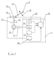
- This thread guide elements 13 are arranged at the front end of a lever 14 (Fig. 2 and 3), opposite with the help of a stepper motor 15 a carrier 16 is rotatable.
- the stepper motor 15 is controlled by a control device 17, so that the thread guide element 13 its position in the direction a double arrow 18 can change. Through the Pivoting the lever 14 changes the axial position of the thread guide element 13 relative to the warping drum 1.
- a thread thickness measuring device 20 is in the movement path the threads 12 arranged.
- the thread thickness measuring device 20 has a measuring field 21 through which each thread 12 is guided on a circular path. He shadows you Sensor 22 depending on its thickness.
- the thread thickness measuring device 20 thus determines each Thread 12 once per revolution (direction 23) the thickness and reports the thickness to the control device 17.
- Sorting fingers 24, 25, 26 are on the partial bars 4, 5, 6 arranged at the end that the rotary gate 7th is facing.
- the sorting fingers 24 to 26 are used to to guide the threads 12 so that they are either radially outside of the partial rods 4, 5, 6 or radially within the Partial rods 4, 5, 6 come to rest, each based on the warping drum 1.
- Using the sorting fingers 24 to 26 it is possible to form crosses. Crosses are needed at the beginning and at the end of a chain, on the one hand the To separate threads (partial crosses) and on the other hand the Being able to cut threads (cutting crosses).
- Fig. 1 three partial bars 4-6 are shown. But it can there may also be more partial bars, for example four. On the back of the not visible in Fig. 1 Warping machine additional bars can be arranged.
- the thread guides 11 by a rotational movement of the carrier 16 the warping drum 1 led around.
- Each thread comes with a number of turns around the warping drum 1, multiplied by the size of the warping drum 1 later gives the desired warp length. If, for example a warp length of 700 m is desired and the Warping drum has a circumference of 7 m, then everyone Thread with 100 turns around warping drum 1.
- the levers 14 are pivoted by the stepper motor 15.
- the lever 14 has a length, for example of about 100 mm, so that a correspondingly long cone can be generated, which is favorable to the maximum Warp length affects.
- the thread guide elements 13 are thus in a kind Threaded around the circumference of the warping drum 1.
- This helix can be both continuous Have slope in the direction of arrow 3, as well as a series of circular movements be composed, at predetermined angular positions the carrier 16 jumps from a circular path to the next circular path.
- the arm 14 swiveled back to its starting point relatively quickly be so that the next thread again on Foot of the previously formed cone on the circumference of the Warping drum 1 can be wound.
- the stepper motor 15 can be controlled accordingly.
- the control should now be based on the schematic representation of the Fig. 4 will be explained. The same elements are included here provided with the same reference numerals.
- Adjacent to the shaft 19 is an angle encoder 30 which is connected to an angle sensor 31 cooperates.
- the angle sensor 31 works together with an angle detection device 32, which continuously forms an angle ⁇ of a beam 16 notes.
- the positions of the other carriers result so automatically because the other carriers one predetermined angular distance to that shown in FIG. 4 Have carrier 16.
- the desired trajectory is in a program memory 33 of the thread guide element 13 in dependence deposited by the rotation of the carrier 16.
- One in the program memory 33 stored program can for example look so that the thread guide element around 50 times the scope of the warping drum is moved and at every revolution by 1.2 mm in the direction of arrow 3. At the end of the 50th turn, the thread guide element 13 again by 60 mm against the direction of the Arrow 3 moved back.
- the program memory 33 now transfers the information the desired sequence of movements to a motor control 34 further.
- the engine controller 34 generates for a predetermined one Angular increment that the carrier 16 has traveled has a predetermined number of step pulses to control the stepper motor 15.
- the lever 14 is dependent on the movement of the carrier 16 moves. If the carrier 16 rotated faster is, then the lever 14 is pivoted faster. If the carrier 16 is rotated more slowly, then the lever 14 has more for the same movement Time, i.e. the step impulses for the stepper motor 15 are moving at a slower speed, i.e. With given larger intervals.
- the angle sensor 35 is only here for the purpose of simpler Explanation drawn. Usually reports the stepper motor 15 its angular position to the control device 17 back so that this information in the Control device 17 is already available. she can then be taken into account in the correction device 36 become.
- the angle detection device 32 is provided with a rotation speed determination device 37 connected, which is an angular velocity ⁇ by temporal differentiation of the angle of rotation ⁇ is determined.
- the speed ⁇ can also be determined in other ways become.
- the rotational speed detection device 37 is connected to the engine control 34 and to following purpose: A movement of the lever 14 sets one appropriate control of the stepper motor 15 ahead. However, the stepper motor 15 only reacts with one certain delay to a corresponding control signal. This delay is in the range of a few Milliseconds, for example 4 to 6 ms.
- the delay time is essentially constant. In Depends on the speed of rotation ⁇ Carrier 16 but different in this constant time Back angular distances.
- the engine control 34 therefore takes into account the speed of rotation of the carrier 16 when they have the drive signal for the stepper motor 15 generated.
- a movement of the Thread guide element 13 should take place at 300 ° C, then a corresponding control signal is generated at 299.5 °, if the thread guide element at a speed of 100 m / min around the circumference of the warping drum 1 is guided around, and at 294 ° when the thread guide element 13 at 1200 m / min around the warping drum 1 becomes.
- stepper motors 15 are individually controllable on the carriers 16, if this is required. This is especially beneficial if partial rods on the front and on the rear side the warping drum 1.
- the thread guide elements 13, the threads 12 can then individually on or under the Store partial bars.
- the thread guide elements 13 can so any "serpentine lines" (curve shape after a or both axial directions differ from one Screw or circular line), without at angular positions of the carrier 16 may be bound. With the control the movement of the threads 12 offers considerable advantages.
- the illustrated embodiment can be used in many ways be deviated. It is shown that the thread guide elements 13 arranged on rod-shaped supports 16 are. You can, however, the individual carriers 16 also replace with a disc or plate on the other Then the thread guide elements 13 are arranged circumferentially. This results in particular at higher working speeds improved stability.
Landscapes
- Engineering & Computer Science (AREA)
- Textile Engineering (AREA)
- Warping, Beaming, Or Leasing (AREA)
Applications Claiming Priority (2)
| Application Number | Priority Date | Filing Date | Title |
|---|---|---|---|
| DE2003123351 DE10323351B4 (de) | 2003-05-23 | 2003-05-23 | Musterkettenschärmaschine |
| DE10323351 | 2003-05-23 |
Publications (3)
| Publication Number | Publication Date |
|---|---|
| EP1479805A2 true EP1479805A2 (fr) | 2004-11-24 |
| EP1479805A3 EP1479805A3 (fr) | 2005-04-20 |
| EP1479805B1 EP1479805B1 (fr) | 2008-12-03 |
Family
ID=33039294
Family Applications (1)
| Application Number | Title | Priority Date | Filing Date |
|---|---|---|---|
| EP20040007006 Expired - Lifetime EP1479805B1 (fr) | 2003-05-23 | 2004-03-24 | Ourdissoir d'échantillonnage |
Country Status (4)
| Country | Link |
|---|---|
| EP (1) | EP1479805B1 (fr) |
| JP (1) | JP2004346479A (fr) |
| DE (2) | DE10323351B4 (fr) |
| ES (1) | ES2315583T3 (fr) |
Cited By (1)
| Publication number | Priority date | Publication date | Assignee | Title |
|---|---|---|---|---|
| CN102851818A (zh) * | 2011-06-28 | 2013-01-02 | 卡尔迈尔纺织机械制造有限公司 | 花式整经机 |
Families Citing this family (3)
| Publication number | Priority date | Publication date | Assignee | Title |
|---|---|---|---|---|
| JP2007070759A (ja) * | 2005-09-07 | 2007-03-22 | Murata Mach Ltd | 荒巻整経システム及び荒巻整経方法 |
| EP2284303B1 (fr) * | 2009-08-12 | 2011-11-23 | Karl Mayer Textilmaschinenfabrik GmbH | Râtelier d'un ourdissoir d'échantillonnage, ourdissoir d'échantillonnage et procédé de mesure d'un diamètre de bobine |
| CN105463654B (zh) * | 2015-11-17 | 2018-06-29 | 青海德瑞纺织品进出口有限公司 | 一种球形整经机及其使用方法 |
Family Cites Families (7)
| Publication number | Priority date | Publication date | Assignee | Title |
|---|---|---|---|---|
| JPH02169737A (ja) * | 1988-12-22 | 1990-06-29 | Suzuki Waapaa:Kk | 複本数同時整経可能な電子制御サンプル整経機 |
| DE4304956C2 (de) * | 1993-02-18 | 1998-09-24 | Mayer Textilmaschf | Verfahren und Vorrichtung zum Schären von Fäden |
| DE4446279C1 (de) * | 1994-12-23 | 1996-06-27 | Mayer Textilmaschf | Vorrichtung und Verfahren zum Herstellen von Kurzketten |
| DE19845244C1 (de) * | 1998-10-01 | 1999-09-23 | Mayer Textilmaschf | Musterketten-Schärmaschine |
| JP3410433B2 (ja) * | 2000-06-01 | 2003-05-26 | 有限会社スズキワーパー | サンプル整経機、整経方法及び整経された糸群 |
| JP3409025B2 (ja) * | 2000-08-22 | 2003-05-19 | 有限会社スズキワーパー | ヤーンガイドの糸検出装置付サンプル整経機 |
| DE10057356B4 (de) * | 2000-11-18 | 2005-11-24 | Karl Mayer Textilmaschinenfabrik Gmbh | Verfahren zum Erzeugen einer Musterkette und Musterketten-Schärmaschine |
-
2003
- 2003-05-23 DE DE2003123351 patent/DE10323351B4/de not_active Expired - Fee Related
-
2004
- 2004-03-24 EP EP20040007006 patent/EP1479805B1/fr not_active Expired - Lifetime
- 2004-03-24 DE DE200450008569 patent/DE502004008569D1/de not_active Expired - Lifetime
- 2004-03-24 ES ES04007006T patent/ES2315583T3/es not_active Expired - Lifetime
- 2004-05-21 JP JP2004151592A patent/JP2004346479A/ja active Pending
Cited By (3)
| Publication number | Priority date | Publication date | Assignee | Title |
|---|---|---|---|---|
| CN102851818A (zh) * | 2011-06-28 | 2013-01-02 | 卡尔迈尔纺织机械制造有限公司 | 花式整经机 |
| EP2540883A1 (fr) * | 2011-06-28 | 2013-01-02 | Karl Mayer Textilmaschinenfabrik GmbH | Ourdissoir d'échantillonnage |
| CN102851818B (zh) * | 2011-06-28 | 2015-01-14 | 卡尔迈尔纺织机械制造有限公司 | 花式整经机 |
Also Published As
| Publication number | Publication date |
|---|---|
| DE502004008569D1 (de) | 2009-01-15 |
| JP2004346479A (ja) | 2004-12-09 |
| DE10323351B4 (de) | 2006-09-14 |
| DE10323351A1 (de) | 2004-12-23 |
| EP1479805A3 (fr) | 2005-04-20 |
| EP1479805B1 (fr) | 2008-12-03 |
| ES2315583T3 (es) | 2009-04-01 |
Similar Documents
| Publication | Publication Date | Title |
|---|---|---|
| DE3319620C2 (fr) | ||
| DE69413315T2 (de) | Verfahren und Vorrichtung zur Fadenverlegung auf einer Spule mit einer genuteten Antriebswalze | |
| CH644647A5 (de) | Verfahren zur ueberwachung eines webstuhls und vorrichtung zur durchfuehrung des verfahrens. | |
| EP0150771B2 (fr) | Paquet de fil enroulé par bobinage de précision, procédé et dispositif pour sa réalisation | |
| CH662104A5 (de) | Verfahren zum aufwickeln von garn auf einen sich drehenden wickel und vorrichtung zur durchfuehrung des verfahrens. | |
| EP0768271B1 (fr) | Bobinoir pour un fil en déplacement continu | |
| CH662368A5 (de) | Vorrichtung zur herstellung von kurzketten, insbesondere fuer gewebemuster in der buntweberei. | |
| EP1479805B1 (fr) | Ourdissoir d'échantillonnage | |
| DE4428143A1 (de) | Röntgenabbildungssystem | |
| DE3801584A1 (de) | Universal-rundstrickmaschine mit zwei zylindern und mehreren abwuerfen | |
| WO2017216117A1 (fr) | Métier à tisser à aiguilles pour rubans et procédé de tissage correspondant | |
| DE2016065C3 (de) | Kettablaßeinrlchtung | |
| EP1445361B1 (fr) | Méthode d'ourdissage et ourdissoir d'échantillonnage | |
| EP1479803B1 (fr) | Méthode pour obtenir une chaîne d'échantillonnage et ourdissoir d'échantillonnage | |
| EP1930489B1 (fr) | Ourdissoir d'échantillonnage et procédé pour obtenir une chaîne d'échantillonnage | |
| EP1479804B1 (fr) | Méthode pour obtenir une chaîne d'échantillonnage et ourdissoir d'échantillonnage | |
| EP2540882A1 (fr) | Ourdissoir d'échantillonnage | |
| EP2975176B1 (fr) | Dispositif de fabrication de tamis à spirales | |
| DE2920682A1 (de) | Umflechtmaschine, insbesondere fuer kabel | |
| DE10057356B4 (de) | Verfahren zum Erzeugen einer Musterkette und Musterketten-Schärmaschine | |
| DE10057354B4 (de) | Verfahren zum Erzeugen einer Musterkette und Musterketten-Schärmaschine | |
| EP1035242B1 (fr) | Ourdissoir d'échantillonnage | |
| DE2345720A1 (de) | Verfahren und vorrichtung zum herstellen von litze | |
| EP0924007B1 (fr) | Dispositif de coupage de fil en tronçons de longeurs prédéterminées | |
| DE2844903C2 (fr) |
Legal Events
| Date | Code | Title | Description |
|---|---|---|---|
| PUAI | Public reference made under article 153(3) epc to a published international application that has entered the european phase |
Free format text: ORIGINAL CODE: 0009012 |
|
| AK | Designated contracting states |
Kind code of ref document: A2 Designated state(s): AT BE BG CH CY CZ DE DK EE ES FI FR GB GR HU IE IT LI LU MC NL PL PT RO SE SI SK TR |
|
| AX | Request for extension of the european patent |
Extension state: AL LT LV MK |
|
| PUAL | Search report despatched |
Free format text: ORIGINAL CODE: 0009013 |
|
| AK | Designated contracting states |
Kind code of ref document: A3 Designated state(s): AT BE BG CH CY CZ DE DK EE ES FI FR GB GR HU IE IT LI LU MC NL PL PT RO SE SI SK TR |
|
| AX | Request for extension of the european patent |
Extension state: AL LT LV MK |
|
| 17P | Request for examination filed |
Effective date: 20050330 |
|
| AKX | Designation fees paid |
Designated state(s): CH DE ES IT LI |
|
| GRAP | Despatch of communication of intention to grant a patent |
Free format text: ORIGINAL CODE: EPIDOSNIGR1 |
|
| GRAS | Grant fee paid |
Free format text: ORIGINAL CODE: EPIDOSNIGR3 |
|
| GRAS | Grant fee paid |
Free format text: ORIGINAL CODE: EPIDOSNIGR3 |
|
| GRAA | (expected) grant |
Free format text: ORIGINAL CODE: 0009210 |
|
| AK | Designated contracting states |
Kind code of ref document: B1 Designated state(s): CH DE ES IT LI |
|
| REG | Reference to a national code |
Ref country code: CH Ref legal event code: NV Representative=s name: BOVARD AG PATENTANWAELTE Ref country code: CH Ref legal event code: EP |
|
| REF | Corresponds to: |
Ref document number: 502004008569 Country of ref document: DE Date of ref document: 20090115 Kind code of ref document: P |
|
| REG | Reference to a national code |
Ref country code: ES Ref legal event code: FG2A Ref document number: 2315583 Country of ref document: ES Kind code of ref document: T3 |
|
| PLBE | No opposition filed within time limit |
Free format text: ORIGINAL CODE: 0009261 |
|
| STAA | Information on the status of an ep patent application or granted ep patent |
Free format text: STATUS: NO OPPOSITION FILED WITHIN TIME LIMIT |
|
| 26N | No opposition filed |
Effective date: 20090904 |
|
| PGFP | Annual fee paid to national office [announced via postgrant information from national office to epo] |
Ref country code: CH Payment date: 20100325 Year of fee payment: 7 Ref country code: ES Payment date: 20100324 Year of fee payment: 7 |
|
| REG | Reference to a national code |
Ref country code: CH Ref legal event code: PFA Owner name: KARL MAYER TEXTILMASCHINENFABRIK GMBH Free format text: KARL MAYER TEXTILMASCHINENFABRIK GMBH#BRUEHLSTRASSE 25#63179 OBERTSHAUSEN (DE) -TRANSFER TO- KARL MAYER TEXTILMASCHINENFABRIK GMBH#BRUEHLSTRASSE 25#63179 OBERTSHAUSEN (DE) |
|
| REG | Reference to a national code |
Ref country code: CH Ref legal event code: PL |
|
| PG25 | Lapsed in a contracting state [announced via postgrant information from national office to epo] |
Ref country code: CH Free format text: LAPSE BECAUSE OF NON-PAYMENT OF DUE FEES Effective date: 20110331 Ref country code: LI Free format text: LAPSE BECAUSE OF NON-PAYMENT OF DUE FEES Effective date: 20110331 |
|
| REG | Reference to a national code |
Ref country code: ES Ref legal event code: FD2A Effective date: 20120424 |
|
| PG25 | Lapsed in a contracting state [announced via postgrant information from national office to epo] |
Ref country code: ES Free format text: LAPSE BECAUSE OF NON-PAYMENT OF DUE FEES Effective date: 20110325 |
|
| REG | Reference to a national code |
Ref country code: DE Ref legal event code: R082 Ref document number: 502004008569 Country of ref document: DE Ref country code: DE Ref legal event code: R082 Ref document number: 502004008569 Country of ref document: DE Representative=s name: KEIL & SCHAAFHAUSEN PATENT- UND RECHTSANWAELTE, DE |
|
| REG | Reference to a national code |
Ref country code: DE Ref legal event code: R082 Ref document number: 502004008569 Country of ref document: DE Ref country code: DE Ref legal event code: R081 Ref document number: 502004008569 Country of ref document: DE Owner name: KARL MAYER R&D GMBH, DE Free format text: FORMER OWNER: KARL MAYER TEXTILMASCHINENFABRIK GMBH, 63179 OBERTSHAUSEN, DE Ref country code: DE Ref legal event code: R081 Ref document number: 502004008569 Country of ref document: DE Owner name: KARL MAYER STOLL R&D GMBH, DE Free format text: FORMER OWNER: KARL MAYER TEXTILMASCHINENFABRIK GMBH, 63179 OBERTSHAUSEN, DE |
|
| PGFP | Annual fee paid to national office [announced via postgrant information from national office to epo] |
Ref country code: IT Payment date: 20230321 Year of fee payment: 20 Ref country code: DE Payment date: 20230328 Year of fee payment: 20 |
|
| P01 | Opt-out of the competence of the unified patent court (upc) registered |
Effective date: 20230705 |
|
| REG | Reference to a national code |
Ref country code: DE Ref legal event code: R071 Ref document number: 502004008569 Country of ref document: DE |