EP1480016A1 - Verfahren zur Justierung von optischen Geberelementen - Google Patents
Verfahren zur Justierung von optischen Geberelementen Download PDFInfo
- Publication number
- EP1480016A1 EP1480016A1 EP03011738A EP03011738A EP1480016A1 EP 1480016 A1 EP1480016 A1 EP 1480016A1 EP 03011738 A EP03011738 A EP 03011738A EP 03011738 A EP03011738 A EP 03011738A EP 1480016 A1 EP1480016 A1 EP 1480016A1
- Authority
- EP
- European Patent Office
- Prior art keywords
- section
- sensor
- sensor area
- optical transmitter
- centering
- Prior art date
- Legal status (The legal status is an assumption and is not a legal conclusion. Google has not performed a legal analysis and makes no representation as to the accuracy of the status listed.)
- Granted
Links
- 230000003287 optical effect Effects 0.000 title claims abstract description 26
- 238000000034 method Methods 0.000 title claims description 20
- 238000006073 displacement reaction Methods 0.000 claims 2
- 230000011664 signaling Effects 0.000 abstract 1
- 238000004519 manufacturing process Methods 0.000 description 8
- 238000010276 construction Methods 0.000 description 2
- 239000000463 material Substances 0.000 description 2
- 230000001771 impaired effect Effects 0.000 description 1
- 238000009434 installation Methods 0.000 description 1
- 238000005259 measurement Methods 0.000 description 1
- 229910000679 solder Inorganic materials 0.000 description 1
- 238000005476 soldering Methods 0.000 description 1
Images


Classifications
-
- G—PHYSICS
- G01—MEASURING; TESTING
- G01D—MEASURING NOT SPECIALLY ADAPTED FOR A SPECIFIC VARIABLE; ARRANGEMENTS FOR MEASURING TWO OR MORE VARIABLES NOT COVERED IN A SINGLE OTHER SUBCLASS; TARIFF METERING APPARATUS; MEASURING OR TESTING NOT OTHERWISE PROVIDED FOR
- G01D5/00—Mechanical means for transferring the output of a sensing member; Means for converting the output of a sensing member to another variable where the form or nature of the sensing member does not constrain the means for converting; Transducers not specially adapted for a specific variable
- G01D5/26—Mechanical means for transferring the output of a sensing member; Means for converting the output of a sensing member to another variable where the form or nature of the sensing member does not constrain the means for converting; Transducers not specially adapted for a specific variable characterised by optical transfer means, i.e. using infrared, visible, or ultraviolet light
- G01D5/32—Mechanical means for transferring the output of a sensing member; Means for converting the output of a sensing member to another variable where the form or nature of the sensing member does not constrain the means for converting; Transducers not specially adapted for a specific variable characterised by optical transfer means, i.e. using infrared, visible, or ultraviolet light with attenuation or whole or partial obturation of beams of light
- G01D5/34—Mechanical means for transferring the output of a sensing member; Means for converting the output of a sensing member to another variable where the form or nature of the sensing member does not constrain the means for converting; Transducers not specially adapted for a specific variable characterised by optical transfer means, i.e. using infrared, visible, or ultraviolet light with attenuation or whole or partial obturation of beams of light the beams of light being detected by photocells
- G01D5/347—Mechanical means for transferring the output of a sensing member; Means for converting the output of a sensing member to another variable where the form or nature of the sensing member does not constrain the means for converting; Transducers not specially adapted for a specific variable characterised by optical transfer means, i.e. using infrared, visible, or ultraviolet light with attenuation or whole or partial obturation of beams of light the beams of light being detected by photocells using displacement encoding scales
- G01D5/34707—Scales; Discs, e.g. fixation, fabrication, compensation
-
- G—PHYSICS
- G05—CONTROLLING; REGULATING
- G05B—CONTROL OR REGULATING SYSTEMS IN GENERAL; FUNCTIONAL ELEMENTS OF SUCH SYSTEMS; MONITORING OR TESTING ARRANGEMENTS FOR SUCH SYSTEMS OR ELEMENTS
- G05B2219/00—Program-control systems
- G05B2219/30—Nc systems
- G05B2219/37—Measurements
- G05B2219/37175—Normal encoder, disk for pulses, incremental
-
- G—PHYSICS
- G05—CONTROLLING; REGULATING
- G05B—CONTROL OR REGULATING SYSTEMS IN GENERAL; FUNCTIONAL ELEMENTS OF SUCH SYSTEMS; MONITORING OR TESTING ARRANGEMENTS FOR SUCH SYSTEMS OR ELEMENTS
- G05B2219/00—Program-control systems
- G05B2219/30—Nc systems
- G05B2219/37—Measurements
- G05B2219/37182—Slit plate encoder
Definitions
- the invention relates to a method for centering optical encoder elements in Form of timing disks or rulers on drive shafts, tool and / or Control carriage and on vertically or horizontally movable position sensors, whereby the optical sensor elements on the edge in the sensor area of a device for Intervene motion control.
- the invention further relates to an optical Transmitter element for performing the method described above.
- Clock disks are usually attached to a rotating axis by means of a hub. Both translucent and reflective clock disks are used. With the translucent clock disk, the light beam emitted in the emitter creates in the transmitted light process during the rotation of the disc impulses on the opposite side of the clock disk received by a sensor element become. The sensor and emitter elements rest on the reflective clock disk one side of the clock disk, usually parallel to the axis of rotation, so that on the clock disk or clock rulers can be scanned in the narrowest space.
- the object of the present invention is therefore to provide a method and Implementation of the method to develop a suitable optical transmitter element with a centering of the timing disks or rulers on drive shafts, tools and / or Control sled and on vertically or horizontally movable position sensors is made possible with high accuracy.
- Fig. 1 is an optical encoder element 1 with an opening 2 for attachment a drive shaft 3 shown.
- a side of the encoder element 1 Sensor emitter unit 4 which is attached to a circuit board 5.
- the circuit board 5 in turn sits on the flange side of an electric motor 6, which is soldered over Connections (not shown) in contact with a connector 7.
- the clock disk used as the optical transmitter element is centered on the shaft 3 in relation to the sensor-emitter unit 4.
- the centering is like this make that absolute in a sensor area 8 of the sensor-emitter unit 4 constant measurement conditions prevail, so that those arranged on the clock disc Code marks when passing through the sensor area 8 no pulse fluctuations produce.
- the clock disk shown in plan view in FIG. 2 also shows in the circumferential direction constant distance revolving code marks 9 with an accuracy of ⁇ 1 / 1,000,000 m were applied photo-optically.
- FIG. 2 there is also a scanning zone - referred to here as "sensor projection surface" 10 shown with the width A, which is congruent with the sensor area 8 according to FIG. 1 is.
- the light signal emanating from the emitter area is converted into electrical Impulses converted.
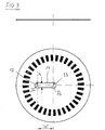
- FIG. 3 shows, analogously to FIG. 2, a clock disk in a top view, with the opening 2 here as dumbbell-shaped hole 11 is shown.
- This version ensures a optimal centering of the new optical encoder element and at the same time ensures that Reaching the end positions using a "locking function".
- the locking function is thereby achieved that the transfer area between the mounting portion 12 and the Centering section 13 has a smaller width b than the diameter D1, D2 in the Assembly or centering sections.
- FIGS. 1 to 3 show a simple one Construction.
- the feed movement of the clock disk from the mounting position into the Adjustment position is straight, so that automatic production is easy to implement is.
- the manufacturing processes shown in the examples can be easily optimized, whereby high process reliability is guaranteed in all cases.
Landscapes
- Physics & Mathematics (AREA)
- General Physics & Mathematics (AREA)
- Optical Transform (AREA)
- Moving Of The Head For Recording And Reproducing By Optical Means (AREA)
Abstract
Description
- Fig. 1
- Gesamtansicht einer Vorrichtung zur Bewegungssteuerung im montierten Zustand
- Fig. 2
- Optisches Geberelement mit Langlochausschnitt
- Fig. 3
- Optisches Geberelement mit Formloch-Ausschnitt
Claims (10)
- Verfahren zur Zentrierung von optischen Geberelementen in Form von Taktscheiben oder Taktlinealen auf Antriebswellen, Werkzeug- und/oder Steuerschlitten sowie auf vertikal oder horizontal beweglichen Positionsgebern, wobei die Geberelemente randseitig in den Sensorbereich einer Vorrichtung zur Bewegungssteuerung eingreifen, dadurch gekennzeichnet, dass die Zentrierung über einen Ausschnitt im optischen Geberelement zweistufig erfolgt, wobei das optische Geberelement in der ersten Stufe außerhalb des Sensorbereiches vorjustiert und in der zweiten Stufe durch seitliches Verschieben in den Sensorbereich hinein feinjustiert wird.
- Verfahren nach Anspruch 1, dadurch gekennzeichnet, dass die Verschiebung in den Sensorbereich hinein entlang einer auf den Sensorbereich zulaufenden Führungsfläche im optischen Geberelement erfolgt.
- Verfahren nach einem der vorhergehenden Ansprüche, dadurch gekennzeichnet, dass in der feinjustierten Position des optischen Geberelementes eine formschlüssige und/oder kraftschlüssige Fixierung auf den Antriebselementen, dem Werkzeug und/oder Steuerschlitten sowie auf den horizontal oder vertikal beweglichen Maschinenelementen erfolgt.
- Verfahren nach einem der vorhergehenden Ansprüche, dadurch gekennzeichnet, dass das Geberelement eine Taktscheibe ist und die Führungsfläche als Langloch ausgebildet ist, das von der Montageposition außerhalb des Sensorbereiches radial zu der Justierposition im Sensorbereich verläuft.
- Verfahren nach einem der vorhergehenden Ansprüche, dadurch gekennzeichnet, dass die Justierposition im Kreismittelpunkt der Taktscheibe angeordnet ist und der Bereich zur Montageposition als Transferabschnitt ausgebildet ist, wobei die Führungsflächen des Transferabschnitts eine geringere Öffnungsweite als in der Montage- und Justierposition aufweisen.
- Optisches Geberelement (1) mit einer Öffnung (2) für die Befestigung auf Antriebswellen (3), Werkzeug- und/oder Steuerschlitten sowie auf horizontal oder vertikal beweglichen Maschinenelementen wobei das Geberelement randseitig in den Sensorbereich (8) einer Vorrichtung zur Bewegungssteuerung eingreift, dadurch gekennzeichnet, dass die Öffnung (2) aus einem Montageabschnitt 3.1 und einem Zentrierabschnitt 3.2 besteht, wobei der Abstand bzw. die Länge a zwischen beiden Abschnitten gleich oder größer als die vom Sensor überdeckte Breite A (Sensorprojektionsfläche 10) ist.
- Optisches Geberelement nach dem vorhergehenden Anspruch, dadurch gekennzeichnet, dass der zentrierende Abschnitt 3.2 als form und/oder kraftschlüssige Passung für die Befestigung auf dem Antriebselement, dem Werkzeug und/oder Steuerschlitten sowie auf den horizontal oder vertikal beweglichen Maschinenelementen ausgebildet ist.
- Optisches Geberelement nach einem der vorhergehenden Ansprüche, dadurch gekennzeichnet, dass das Antriebselement eine Motorwelle (3) aufweist.
- Optisches Geberelement nach einem der vorhergehenden Ansprüche, dadurch gekennzeichnet, dass der Montageabschnitt 3.1 über einen eng tolerierten Transferabschnitt 3.3 mit dem Zentrierabschnitt 3.2 verbunden ist, wobei die Länge "a" des Transferabschnitts mindestens gleich oder größer als die vom Sensor überdeckte Breite A bemessen ist.
- Optisches Geberelement nach einem der vorhergehenden Ansprüche, dadurch gekennzeichnet, dass Zentrierabschnitt 3.2, Transferabschnitt 3.3 und Montageabschnitt 3.1 hantelförmig ausgebildet sind.
Priority Applications (8)
| Application Number | Priority Date | Filing Date | Title |
|---|---|---|---|
| AT03011738T ATE408804T1 (de) | 2003-05-23 | 2003-05-23 | Verfahren zur justierung von optischen geberelementen |
| DE50310512T DE50310512D1 (de) | 2003-05-23 | 2003-05-23 | Verfahren zur Justierung von optischen Geberelementen |
| EP03011738A EP1480016B1 (de) | 2003-05-23 | 2003-05-23 | Verfahren zur Justierung von optischen Geberelementen |
| DE20318625U DE20318625U1 (de) | 2003-05-23 | 2003-12-02 | Optisches Geberelement |
| JP2004153415A JP2004354379A (ja) | 2003-05-23 | 2004-05-24 | 光伝送エレメントのセンタリング方法及びこの方法を実施するための光伝送エレメント |
| US10/853,776 US20050002043A1 (en) | 2003-05-23 | 2004-05-24 | Method for centering an optical transducer element, and optical transducer element for carrying out the method |
| HK05104326.2A HK1074074B (en) | 2005-05-24 | Method for adjusting optical encoders | |
| JP2005009807U JP3119992U (ja) | 2003-05-23 | 2005-11-22 | 光伝送エレメントのセンタリング方法及びこの方法を実施するための光伝送エレメント |
Applications Claiming Priority (1)
| Application Number | Priority Date | Filing Date | Title |
|---|---|---|---|
| EP03011738A EP1480016B1 (de) | 2003-05-23 | 2003-05-23 | Verfahren zur Justierung von optischen Geberelementen |
Publications (2)
| Publication Number | Publication Date |
|---|---|
| EP1480016A1 true EP1480016A1 (de) | 2004-11-24 |
| EP1480016B1 EP1480016B1 (de) | 2008-09-17 |
Family
ID=32088139
Family Applications (1)
| Application Number | Title | Priority Date | Filing Date |
|---|---|---|---|
| EP03011738A Expired - Lifetime EP1480016B1 (de) | 2003-05-23 | 2003-05-23 | Verfahren zur Justierung von optischen Geberelementen |
Country Status (5)
| Country | Link |
|---|---|
| US (1) | US20050002043A1 (de) |
| EP (1) | EP1480016B1 (de) |
| JP (2) | JP2004354379A (de) |
| AT (1) | ATE408804T1 (de) |
| DE (2) | DE50310512D1 (de) |
Families Citing this family (2)
| Publication number | Priority date | Publication date | Assignee | Title |
|---|---|---|---|---|
| JP5838649B2 (ja) * | 2011-08-12 | 2016-01-06 | 株式会社リコー | モータユニット及びそれを有する画像形成装置 |
| JP6227242B2 (ja) * | 2012-11-22 | 2017-11-08 | ミネベアミツミ株式会社 | 光学式エンコーダ、光学式エンコーダ付きモータおよびその製造方法 |
Citations (2)
| Publication number | Priority date | Publication date | Assignee | Title |
|---|---|---|---|---|
| JPS59185876A (ja) * | 1983-04-07 | 1984-10-22 | Mitsubishi Electric Corp | 機関点火用配電器の光電式信号発生装置 |
| US4972599A (en) * | 1989-05-13 | 1990-11-27 | Dr. Johannes Heidenhain Gmbh | Position measuring device with an adjusting device |
Family Cites Families (1)
| Publication number | Priority date | Publication date | Assignee | Title |
|---|---|---|---|---|
| US6457752B1 (en) * | 2000-01-21 | 2002-10-01 | Hughes Supply Company Of Thomasville, Inc. | Locking window |
-
2003
- 2003-05-23 AT AT03011738T patent/ATE408804T1/de not_active IP Right Cessation
- 2003-05-23 DE DE50310512T patent/DE50310512D1/de not_active Expired - Fee Related
- 2003-05-23 EP EP03011738A patent/EP1480016B1/de not_active Expired - Lifetime
- 2003-12-02 DE DE20318625U patent/DE20318625U1/de not_active Expired - Lifetime
-
2004
- 2004-05-24 JP JP2004153415A patent/JP2004354379A/ja active Pending
- 2004-05-24 US US10/853,776 patent/US20050002043A1/en not_active Abandoned
-
2005
- 2005-11-22 JP JP2005009807U patent/JP3119992U/ja not_active Expired - Fee Related
Patent Citations (2)
| Publication number | Priority date | Publication date | Assignee | Title |
|---|---|---|---|---|
| JPS59185876A (ja) * | 1983-04-07 | 1984-10-22 | Mitsubishi Electric Corp | 機関点火用配電器の光電式信号発生装置 |
| US4972599A (en) * | 1989-05-13 | 1990-11-27 | Dr. Johannes Heidenhain Gmbh | Position measuring device with an adjusting device |
Non-Patent Citations (1)
| Title |
|---|
| PATENT ABSTRACTS OF JAPAN vol. 009, no. 046 (M - 360) 27 February 1985 (1985-02-27) * |
Also Published As
| Publication number | Publication date |
|---|---|
| JP2004354379A (ja) | 2004-12-16 |
| DE20318625U1 (de) | 2004-04-01 |
| EP1480016B1 (de) | 2008-09-17 |
| US20050002043A1 (en) | 2005-01-06 |
| ATE408804T1 (de) | 2008-10-15 |
| HK1074074A1 (zh) | 2005-10-28 |
| DE50310512D1 (de) | 2008-10-30 |
| JP3119992U (ja) | 2006-03-23 |
Similar Documents
| Publication | Publication Date | Title |
|---|---|---|
| DE69114262T2 (de) | Apparateinheit zur ausrichtung und festlegung des zwischenraums für bausteine für optische winkelkodierer. | |
| EP0307421B1 (de) | Revolver-dreheinrichtung für optische bauelemente sowie verfahren zur regelung der drehzahl derselben | |
| EP0048487A2 (de) | Verfahren zur Herstellung einer Codescheibe für optische Winkelschrittgeber bzw. Winkelcodierer | |
| EP0981457B1 (de) | Antriebsvorrichtung für ein zwischen endstellungen bewegbares teil eines fahrzeugs und verfahren zu ihrer herstellung | |
| DE2840963A1 (de) | Optischer rotationskodierer | |
| EP0819913A1 (de) | Verfahren und Vorrichtung zur Positionierung von nicht-geradlinigen bewegten insbesondere rotierenden Maschinenteilen | |
| EP2063230A2 (de) | Optische Positionsmesseinrichtung | |
| EP0913669A2 (de) | Verfahren zum Anbringen einer Winkelteilung an einer Teilscheibe für Rotationsmesssysteme sowie Teilscheibe mit Winkelteilung für Rotationsmesssysteme | |
| DE3441429A1 (de) | Optischer drehcodierer | |
| EP1089053B1 (de) | Winkelmesseinrichtung und Verwendung dieser Winkelmesseinrichtung in einer Spindelanordnung | |
| EP1480016A1 (de) | Verfahren zur Justierung von optischen Geberelementen | |
| DE3643164C2 (de) | ||
| DE3348133C2 (de) | ||
| DE19816827B4 (de) | Vormontierte Winkelmeßvorrichtung | |
| EP0909372B1 (de) | Handbetätigter Winkelgeber mit radialer Magnetrastierung | |
| EP1643216A1 (de) | Verfahren zur Herstellung und Montage eines Körpers mit einer Winkelskalierung | |
| EP1452836B1 (de) | Vorrichtung zum Messen des Drehwinkels | |
| EP1767906A2 (de) | Selbstzentrierende Nabe | |
| EP0993666B1 (de) | Signalübertragungseinrichtung | |
| EP0072386B1 (de) | Impulsgeber zum Erzeugen von elektronischen Impulsfolgen | |
| EP3162661B1 (de) | Vorrichtung und verfahren zur erfassung einer ist-stellung eines elektrisch gelenkten rades | |
| DE3112525A1 (de) | Optischer positionssensor | |
| DD154509A1 (de) | Positionskontrolleinrichtung fuer stellantriebe | |
| DE19641164A1 (de) | Drehimpulsgeber | |
| DE1548677C (de) | Gehäuse zur Aufnahme eines digitalen Winkelmeßgerates |
Legal Events
| Date | Code | Title | Description |
|---|---|---|---|
| PUAI | Public reference made under article 153(3) epc to a published international application that has entered the european phase |
Free format text: ORIGINAL CODE: 0009012 |
|
| 17P | Request for examination filed |
Effective date: 20040625 |
|
| AK | Designated contracting states |
Kind code of ref document: A1 Designated state(s): AT BE BG CH CY CZ DE DK EE ES FI FR GB GR HU IE IT LI LU MC NL PT RO SE SI SK TR |
|
| AX | Request for extension of the european patent |
Extension state: AL LT LV MK |
|
| AKX | Designation fees paid |
Designated state(s): AT BE BG CH CY CZ DE DK EE ES FI FR GB GR HU IE IT LI LU MC NL PT RO SE SI SK TR |
|
| REG | Reference to a national code |
Ref country code: HK Ref legal event code: DE Ref document number: 1074074 Country of ref document: HK |
|
| 17Q | First examination report despatched |
Effective date: 20060810 |
|
| 17Q | First examination report despatched |
Effective date: 20060810 |
|
| GRAP | Despatch of communication of intention to grant a patent |
Free format text: ORIGINAL CODE: EPIDOSNIGR1 |
|
| GRAS | Grant fee paid |
Free format text: ORIGINAL CODE: EPIDOSNIGR3 |
|
| GRAA | (expected) grant |
Free format text: ORIGINAL CODE: 0009210 |
|
| AK | Designated contracting states |
Kind code of ref document: B1 Designated state(s): AT BE BG CH CY CZ DE DK EE ES FI FR GB GR HU IE IT LI LU MC NL PT RO SE SI SK TR |
|
| REG | Reference to a national code |
Ref country code: GB Ref legal event code: FG4D Free format text: NOT ENGLISH |
|
| REG | Reference to a national code |
Ref country code: CH Ref legal event code: EP |
|
| REG | Reference to a national code |
Ref country code: IE Ref legal event code: FG4D Free format text: LANGUAGE OF EP DOCUMENT: GERMAN |
|
| REF | Corresponds to: |
Ref document number: 50310512 Country of ref document: DE Date of ref document: 20081030 Kind code of ref document: P |
|
| PG25 | Lapsed in a contracting state [announced via postgrant information from national office to epo] |
Ref country code: SI Free format text: LAPSE BECAUSE OF FAILURE TO SUBMIT A TRANSLATION OF THE DESCRIPTION OR TO PAY THE FEE WITHIN THE PRESCRIBED TIME-LIMIT Effective date: 20080917 Ref country code: FI Free format text: LAPSE BECAUSE OF FAILURE TO SUBMIT A TRANSLATION OF THE DESCRIPTION OR TO PAY THE FEE WITHIN THE PRESCRIBED TIME-LIMIT Effective date: 20080917 |
|
| NLV1 | Nl: lapsed or annulled due to failure to fulfill the requirements of art. 29p and 29m of the patents act | ||
| PG25 | Lapsed in a contracting state [announced via postgrant information from national office to epo] |
Ref country code: ES Free format text: LAPSE BECAUSE OF FAILURE TO SUBMIT A TRANSLATION OF THE DESCRIPTION OR TO PAY THE FEE WITHIN THE PRESCRIBED TIME-LIMIT Effective date: 20081228 Ref country code: BG Free format text: LAPSE BECAUSE OF FAILURE TO SUBMIT A TRANSLATION OF THE DESCRIPTION OR TO PAY THE FEE WITHIN THE PRESCRIBED TIME-LIMIT Effective date: 20081217 |
|
| PG25 | Lapsed in a contracting state [announced via postgrant information from national office to epo] |
Ref country code: CZ Free format text: LAPSE BECAUSE OF FAILURE TO SUBMIT A TRANSLATION OF THE DESCRIPTION OR TO PAY THE FEE WITHIN THE PRESCRIBED TIME-LIMIT Effective date: 20080917 Ref country code: PT Free format text: LAPSE BECAUSE OF FAILURE TO SUBMIT A TRANSLATION OF THE DESCRIPTION OR TO PAY THE FEE WITHIN THE PRESCRIBED TIME-LIMIT Effective date: 20090217 Ref country code: SK Free format text: LAPSE BECAUSE OF FAILURE TO SUBMIT A TRANSLATION OF THE DESCRIPTION OR TO PAY THE FEE WITHIN THE PRESCRIBED TIME-LIMIT Effective date: 20080917 Ref country code: NL Free format text: LAPSE BECAUSE OF FAILURE TO SUBMIT A TRANSLATION OF THE DESCRIPTION OR TO PAY THE FEE WITHIN THE PRESCRIBED TIME-LIMIT Effective date: 20080917 Ref country code: RO Free format text: LAPSE BECAUSE OF FAILURE TO SUBMIT A TRANSLATION OF THE DESCRIPTION OR TO PAY THE FEE WITHIN THE PRESCRIBED TIME-LIMIT Effective date: 20080917 |
|
| PLBE | No opposition filed within time limit |
Free format text: ORIGINAL CODE: 0009261 |
|
| REG | Reference to a national code |
Ref country code: HK Ref legal event code: GR Ref document number: 1074074 Country of ref document: HK |
|
| STAA | Information on the status of an ep patent application or granted ep patent |
Free format text: STATUS: NO OPPOSITION FILED WITHIN TIME LIMIT |
|
| PG25 | Lapsed in a contracting state [announced via postgrant information from national office to epo] |
Ref country code: DK Free format text: LAPSE BECAUSE OF FAILURE TO SUBMIT A TRANSLATION OF THE DESCRIPTION OR TO PAY THE FEE WITHIN THE PRESCRIBED TIME-LIMIT Effective date: 20080917 Ref country code: EE Free format text: LAPSE BECAUSE OF FAILURE TO SUBMIT A TRANSLATION OF THE DESCRIPTION OR TO PAY THE FEE WITHIN THE PRESCRIBED TIME-LIMIT Effective date: 20080917 |
|
| 26N | No opposition filed |
Effective date: 20090618 |
|
| BERE | Be: lapsed |
Owner name: PWB-RUHLATEC INDUSTRIEPRODUKTE G.M.B.H. Effective date: 20090531 |
|
| PG25 | Lapsed in a contracting state [announced via postgrant information from national office to epo] |
Ref country code: MC Free format text: LAPSE BECAUSE OF NON-PAYMENT OF DUE FEES Effective date: 20090531 |
|
| REG | Reference to a national code |
Ref country code: CH Ref legal event code: PL |
|
| GBPC | Gb: european patent ceased through non-payment of renewal fee |
Effective date: 20090523 |
|
| PG25 | Lapsed in a contracting state [announced via postgrant information from national office to epo] |
Ref country code: CH Free format text: LAPSE BECAUSE OF NON-PAYMENT OF DUE FEES Effective date: 20090531 Ref country code: SE Free format text: LAPSE BECAUSE OF FAILURE TO SUBMIT A TRANSLATION OF THE DESCRIPTION OR TO PAY THE FEE WITHIN THE PRESCRIBED TIME-LIMIT Effective date: 20081217 Ref country code: LI Free format text: LAPSE BECAUSE OF NON-PAYMENT OF DUE FEES Effective date: 20090531 |
|
| REG | Reference to a national code |
Ref country code: FR Ref legal event code: ST Effective date: 20100129 |
|
| REG | Reference to a national code |
Ref country code: IE Ref legal event code: MM4A |
|
| PG25 | Lapsed in a contracting state [announced via postgrant information from national office to epo] |
Ref country code: IE Free format text: LAPSE BECAUSE OF NON-PAYMENT OF DUE FEES Effective date: 20090523 Ref country code: FR Free format text: LAPSE BECAUSE OF NON-PAYMENT OF DUE FEES Effective date: 20090602 |
|
| PG25 | Lapsed in a contracting state [announced via postgrant information from national office to epo] |
Ref country code: GB Free format text: LAPSE BECAUSE OF NON-PAYMENT OF DUE FEES Effective date: 20090523 |
|
| PG25 | Lapsed in a contracting state [announced via postgrant information from national office to epo] |
Ref country code: BE Free format text: LAPSE BECAUSE OF NON-PAYMENT OF DUE FEES Effective date: 20090531 Ref country code: DE Free format text: LAPSE BECAUSE OF NON-PAYMENT OF DUE FEES Effective date: 20091201 |
|
| PG25 | Lapsed in a contracting state [announced via postgrant information from national office to epo] |
Ref country code: AT Free format text: LAPSE BECAUSE OF NON-PAYMENT OF DUE FEES Effective date: 20090523 |
|
| PG25 | Lapsed in a contracting state [announced via postgrant information from national office to epo] |
Ref country code: GR Free format text: LAPSE BECAUSE OF FAILURE TO SUBMIT A TRANSLATION OF THE DESCRIPTION OR TO PAY THE FEE WITHIN THE PRESCRIBED TIME-LIMIT Effective date: 20081218 |
|
| PG25 | Lapsed in a contracting state [announced via postgrant information from national office to epo] |
Ref country code: IT Free format text: LAPSE BECAUSE OF NON-PAYMENT OF DUE FEES Effective date: 20090523 |
|
| PG25 | Lapsed in a contracting state [announced via postgrant information from national office to epo] |
Ref country code: LU Free format text: LAPSE BECAUSE OF NON-PAYMENT OF DUE FEES Effective date: 20090523 |
|
| PG25 | Lapsed in a contracting state [announced via postgrant information from national office to epo] |
Ref country code: HU Free format text: LAPSE BECAUSE OF FAILURE TO SUBMIT A TRANSLATION OF THE DESCRIPTION OR TO PAY THE FEE WITHIN THE PRESCRIBED TIME-LIMIT Effective date: 20090318 |
|
| PG25 | Lapsed in a contracting state [announced via postgrant information from national office to epo] |
Ref country code: TR Free format text: LAPSE BECAUSE OF FAILURE TO SUBMIT A TRANSLATION OF THE DESCRIPTION OR TO PAY THE FEE WITHIN THE PRESCRIBED TIME-LIMIT Effective date: 20080917 |
|
| PG25 | Lapsed in a contracting state [announced via postgrant information from national office to epo] |
Ref country code: CY Free format text: LAPSE BECAUSE OF FAILURE TO SUBMIT A TRANSLATION OF THE DESCRIPTION OR TO PAY THE FEE WITHIN THE PRESCRIBED TIME-LIMIT Effective date: 20080917 |