EP1480182A2 - Compteur d'essieux sans contact pour traffic routier - Google Patents
Compteur d'essieux sans contact pour traffic routier Download PDFInfo
- Publication number
- EP1480182A2 EP1480182A2 EP04450111A EP04450111A EP1480182A2 EP 1480182 A2 EP1480182 A2 EP 1480182A2 EP 04450111 A EP04450111 A EP 04450111A EP 04450111 A EP04450111 A EP 04450111A EP 1480182 A2 EP1480182 A2 EP 1480182A2
- Authority
- EP
- European Patent Office
- Prior art keywords
- counting system
- axle counting
- unit
- signal
- classifier
- Prior art date
- Legal status (The legal status is an assumption and is not a legal conclusion. Google has not performed a legal analysis and makes no representation as to the accuracy of the status listed.)
- Granted
Links
Images

Classifications
-
- G—PHYSICS
- G08—SIGNALLING
- G08G—TRAFFIC CONTROL SYSTEMS
- G08G1/00—Traffic control systems for road vehicles
- G08G1/01—Detecting movement of traffic to be counted or controlled
-
- G—PHYSICS
- G08—SIGNALLING
- G08G—TRAFFIC CONTROL SYSTEMS
- G08G1/00—Traffic control systems for road vehicles
- G08G1/01—Detecting movement of traffic to be counted or controlled
- G08G1/04—Detecting movement of traffic to be counted or controlled using optical or ultrasonic detectors
Definitions
- the invention relates to a contactless axle counting system for road traffic.
- Non-contact axle counting systems are known in which induction loops are used in the Roadway are integrated. Such systems have the disadvantage that they are in the road must be installed. The road would also have to be dug up in the event of maintenance, which is not associated only with high costs, but also with long-lasting traffic obstructions is.
- the object of the invention is therefore to provide a non-contact axle counting system Avoids the above disadvantages and a with little installation and maintenance reliable axle counting also allows for multi-lane carriageways.
- At least one measuring device for Detection of a moving vehicle in a measuring range e.g. at or near the contact point from tire to road surface, generated changes in the Environmental parameters such as sound, temperature or vibration is provided.
- Such Measuring device is suitable due to its focus on a suitable measuring range, to detect vehicles without contact even in multi-lane sections of the road.
- the at least one measuring device is above the Roadway and above the height of the vehicle is fixed. That way you can Measuring equipment conveniently and inexpensively on existing superstructures the roadway, such as bridges or signage, assembled and serviced become, with an assignment of the measuring devices to lanes particularly simple can be realized.
- the at least one the at least one measuring device is designed as a laser vibrometer.
- Laservibrometer allow high-precision non-contact detection of road vibrations as they occur the weight and / or the natural vibrations of moving vehicles via the tires on the Lane are caused.
- the at least one the at least one measuring device as a directional microphone, in particular as Row microphone system is formed.
- a directional microphone in particular as Row microphone system
- Tire rolling noises particularly easy to detect and localize.
- an analysis unit for Analysis of measurement signals is provided. So the interpretation of the measurement signals be facilitated and improved.
- the analysis unit has a Signal amplification device for amplifying the measurement signals, in particular by one Factor 100 to 10,000. This means that even very weak signals can be evaluated be made accessible.
- the analysis unit has an A / D converter with a Sampling rate of in particular 1 kHz to 50 kHz, or even more specifically between 6 kHz and 16 kHz. Measuring signals digitized in this way are for subsequent data analysis particularly suitable.
- the A / D converter has a resolution of 8 to 24 bits, preferably from 12 to 20 bits. Such a resolution is for subsequent ones Sufficient data analysis and at the same time leads to still manageable amounts of data.
- the analysis unit comprises a computing unit which is arranged downstream of the A / D converter. So they can digitized measurement signals prepared for a classification of the vehicles to be recorded become.
- the computing unit Memory and / or a user interface is connected.
- the memory enables the Storage of parameters influencing the measurement while using the user interface corresponding measurement or environmental parameters can be changed.
- the computing unit has a temporal Segmentation device for dividing discrete time signals into time signal blocks, in particular from a block length of 10 ms to 1,500 ms.
- a temporal Segmentation device enables a higher resolution when analyzing the measurement signals.
- the Computing unit a spectral analyzer for calculating the frequency spectrum of the measurement signals and / or an energy calculation unit for calculating the signal energy, especially the short-term signal energy. From the data calculated in this way Data patterns are generated which are particularly good for a subsequent classification are suitable.
- the computing unit has a Classifier includes the spectral analyzer and / or the energy calculation unit is subordinate, and which from the corresponding calculation results of Spectral analyzer and / or the energy calculation unit resulting data pattern klassizifiert. Data patterns classified in this way enable a particularly reliable Determination of the number of axles of different vehicle types.
- the classifier is in a learning mode, in particular using learning algorithms such as the Hebbian learning process, the Back propagation rule or the forward-backward algorithm, for generation mathematical models can be operated for certain vehicle classes.
- learning algorithms such as the Hebbian learning process, the Back propagation rule or the forward-backward algorithm, for generation mathematical models can be operated for certain vehicle classes.
- the classifier is in a recognition mode can be operated to assign a current measurement signal to a vehicle class. So can a safe, reliable and customized operation of the contactless Axle counting system can be achieved.
- the analysis unit a communication unit is subordinate to the calculation result of the Classifier is passed. This can also be done at a distance, for example in a Central, the number of axles of vehicles that pass a measuring point is recorded and monitored become.
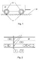
- a vehicle 10 is mechanical via its tires 12 at contact points 11 Interaction with the road surface 20.
- the own movement (vibration) and the relative movement of the vehicle 10 to the road 20 are now mainly in Area of contact points 11 vibrations excited.
- Sound vibrations which are predominantly caused by the rolling of the tires 12 on the road 20, but also caused by engine and flow noises, on the other hand
- Vibrations of the surface of the road 20 itself the amplitude of which in the Order of magnitude of up to a few millimeters.
- the amplitude of the emitted sound waves can be described in different ways become - e.g. than the speed of movement of the air molecules (sonic speed) or as pressure, which is generally preferred for describing the amplitude.
- the sound pressure results from the fluctuation of the air pressure above and below the atmospheric pressure.
- Measuring devices 1, which are used to convert the sound pressure into an electrical signal all suitable sound sensors, e.g. electroacoustic transducers.
- the measuring device 1 can also act as a directional microphone or be designed as a row microphone system, which leads to an improved spatial resolution of a measurement signal.
- the vibrations of the surface of the traffic route can in principle with Accelerometers are measured according to the piezoelectric effect work - but not contactless. These can be achieved using optical methods Vibrations can also be measured without contact.
- Laser vibrometers work on the principle of Doppler frequency shift. This provides a vibrating object (e.g. Surface of a roadway 20) back scattered laser light all information for the Determination of surface speed and absolute vibration amplitudes. in the In contrast to other optical methods (e.g. laser scanners), the distance is not here of an existing object of interest, but the vibration speed of its Surface. With the help of this high-precision measurement, the slightest vibration excitation the surface of the road 20 can be detected.
- the measuring devices are preferably 1 above the carriageway 20 on superstructures such as bridges, signaling devices or Signs attached (see Fig. 2) so that the monitoring of several parallel Lane is easily possible.
- the measuring devices 1 convert the sound or vibration signals into electrical ones Energy around.
- the measuring devices 1 generate analog or digital measurement signals as Function of time.
- the measurement signals generated by the measuring devices 1 are transmitted via separate signal lines or after modulation or coding via a common one Signal line forwarded to the analysis unit 2.
- the measurement signals can also through a wireless connection (e.g. radio, infrared, ...) or via local area networks (LAN) or wireless LAN (WLAN) are transmitted to the analysis unit 2.
- the analysis unit 2 in turn communicates via a communication unit 8 for example with a central unit (not shown) for collection, evaluation or Further processing of the results delivered by the analysis unit 2.
- the connection can be wired or between the communication unit 8 and the central unit done wirelessly.
- FIG. 3 shows the block diagram of the hardware structure of the analysis unit 2.
- the Measurement signals are forwarded to the signal amplification device 3, which contains the measurement signals by a fixed factor, preferably between 100 and 10,000, or with an automatic setting.
- the subsequent analog / digital converter 4 sets the analog signals into discrete values around.
- the sampling rate of the A / D converter 4 can differ from system to system and is generally between 1 kHz and 50 kHz. Are particularly suitable Sampling frequencies between 6 kHz and 16 kHz.
- the resolution of the A / D converter 4 is in the Range from 8 to 24 bits, the range from 12 to 20 bits being preferred.
- the System has a computing unit 5, which with the A / D converter 4 and Data storage 6 is connected.
- the computing unit 5 is used to execute the Calculation steps that are applied to the digitized measurement signals.
- the User interface 7 and memory 6 are connected to computing unit 5. By the user interface 7 can be carried out by a user.
- the User input can be made using any suitable device, e.g. a keyboard, one Mouse, a touchscreen, or any combination of these Devices.
- the result of the analysis is sent via an output to the interface of the Transfer communication unit 8 and processed there.
- FIG. 4 shows the analysis of the measurement signals in the form of a block diagram they take place in the computing unit 5.
- the measurement signals are from the A / D converter 4 a time segmentation 51 is supplied to convert the discrete time signals into time blocks to subdivide, the block length being between 10 ms and 1,500 ms.
- the individual blocks are also extracted from the signal with an overlap. This Overlap is used to increase the resolution and can have values between 20% and 70% accept.
- the data become the one hand Transfer energy calculation unit 53 and the spectral analyzer 52.
- the functionality of the analysis unit 2 is described below.
- the variable t stands for the time, T for the length of a signal block and i stands for the number of the block within the entire acoustic signal.
- s i (t) denotes the measurement signal in the time domain of the i th block, S i (w) the frequency spectrum of the i th block.
- the variable w corresponds to the instantaneous frequency.
- the analysis unit 2 consists of a spectral analyzer 52 and an energy calculation unit 53 for calculating the signal energy.
- the spectral analyzer 52 transforms the individual signal blocks from the time domain into the frequency domain. By default, these transformations are performed using Fourier transformation.
- the so-called Fast Fourier Transformation (FFT) is particularly well suited for this.
- the Fast Fourier Transformation corresponds to a digital approximation of the Fourier transformation.
- the output of the spectrum analyzer 52 corresponds to the power density spectrum of the signal at the entrance and describes the amount of energy at a certain frequency support point.
- the number of frequency sampling points depends on the number of discrete samples, which are taken from the temporal signal for the Fourier transformation, and is in directly related to the block length T mentioned above.
- the Fourier transform others can also be used to calculate the spectral content of a time signal Methods such as the linear prediction coding can be used, which from the literature is known.
- Another component of the analysis unit 2 is the energy calculation unit 53.
- the relationship for determining the signal energy is described by the following equation:
- the course of the signal energy obtained can be significant by the choice of the window length to be influenced.
- the use of large window lengths corresponds to low-pass filtering with a low cut-off frequency and has the consequence that short-term fluctuations of the Signals are not reflected in the signal energy.
- Short window lengths result on the other hand, a course of the signal energy which largely depends on the temporal structure of the based on the acoustic signal.
- the block lengths T for calculating the energy correspond to above values and can be between 10 ms and 1,500 ms.
- classifier 54 Those obtained from the energy calculation and the spectral analyzer 52 Calculation results are then processed in classifier 54.
- the Classifier 54 is able to measure certain data patterns by the Calculation results are formed to classify. That when passing by Vehicles 10 with different number of axles result both for the calculated Energy as well as data spectra determined for the spectrum, which the classifier 54 through the can classify learning patterns presented to him before.
- the classifier 54 can be in two Modes are operated.
- the first mode is also called the learning mode.
- the lem mode is used to generate a mathematical model for each class to be recognized.
- a learning algorithm is a sequence of mathematical calculation steps to approximate a mathematical model in iterative form. Learning algorithms such as the Hebbian learning method, the back propagation rule and the forward backward algorithm are known from the literature.
- the second mode is referred to as the recognition mode and represents the mode that is used in normal operation of the recognition system.
- one of the K signal classes is assigned to a signal that is currently present, and the number of axles of the vehicle 10 that is currently passing is thus determined. The result of the classification is then transferred to the communication unit 8.
Landscapes
- Physics & Mathematics (AREA)
- General Physics & Mathematics (AREA)
- Traffic Control Systems (AREA)
- Length Measuring Devices With Unspecified Measuring Means (AREA)
- Length Measuring Devices By Optical Means (AREA)
Applications Claiming Priority (2)
| Application Number | Priority Date | Filing Date | Title |
|---|---|---|---|
| AT7772003 | 2003-05-20 | ||
| AT0077703A AT412595B (de) | 2003-05-20 | 2003-05-20 | Berührungsloses achszählsystem für den strassenverkehr |
Publications (3)
| Publication Number | Publication Date |
|---|---|
| EP1480182A2 true EP1480182A2 (fr) | 2004-11-24 |
| EP1480182A3 EP1480182A3 (fr) | 2006-01-18 |
| EP1480182B1 EP1480182B1 (fr) | 2007-06-06 |
Family
ID=32932025
Family Applications (1)
| Application Number | Title | Priority Date | Filing Date |
|---|---|---|---|
| EP04450111A Expired - Lifetime EP1480182B1 (fr) | 2003-05-20 | 2004-05-19 | Compteur d'essieux sans contact pour traffic routier |
Country Status (3)
| Country | Link |
|---|---|
| EP (1) | EP1480182B1 (fr) |
| AT (2) | AT412595B (fr) |
| DE (1) | DE502004004010D1 (fr) |
Cited By (3)
| Publication number | Priority date | Publication date | Assignee | Title |
|---|---|---|---|---|
| DE102006054981B3 (de) * | 2006-11-22 | 2008-06-19 | Rtb Gmbh & Co. Kg | Klassifikationseinrichtung für Fahrzeuge |
| WO2022058578A3 (fr) * | 2020-09-21 | 2022-06-16 | Deutsches Zentrum für Luft- und Raumfahrt e.V. | Procédé et dispositif pour surveiller le trafic au moyen des vibrations de la chaussée, par vibrométrie laser |
| DE102022102006A1 (de) | 2022-01-28 | 2023-08-03 | Deutsches Zentrum für Luft- und Raumfahrt e.V. | Erfassen von Verkehrsaktivitäten mit Schwingungssensoren von einem Fahrzeug aus |
Families Citing this family (2)
| Publication number | Priority date | Publication date | Assignee | Title |
|---|---|---|---|---|
| DE102014012285A1 (de) | 2014-08-22 | 2016-02-25 | Jenoptik Robot Gmbh | Verfahren und Achsenzähl-Vorrichtung zur berührungslosen Achsenzählung eines Fahrzeugs sowie Achsenzählsystem für den Straßenverkehr |
| CN114575206A (zh) * | 2022-03-03 | 2022-06-03 | 中国测绘科学研究院 | 一种铁路轨道姿态测量方法、装置及作业系统 |
Family Cites Families (5)
| Publication number | Priority date | Publication date | Assignee | Title |
|---|---|---|---|---|
| US4789941A (en) * | 1986-07-18 | 1988-12-06 | Bennett Nunberg | Computerized vehicle classification system |
| EP0612050B1 (fr) * | 1993-02-19 | 1997-11-05 | Mitsubishi Jukogyo Kabushiki Kaisha | Système de détection de véhicules |
| US5528234A (en) * | 1994-02-01 | 1996-06-18 | Mani; Siva A. | Traffic monitoring system for determining vehicle dimensions, speed, and class |
| US5821879A (en) * | 1996-08-05 | 1998-10-13 | Pacific Sierra Research Corp. | Vehicle axle detector for roadways |
| KR100459475B1 (ko) * | 2002-04-04 | 2004-12-03 | 엘지산전 주식회사 | 차종 판단 시스템 및 그 방법 |
-
2003
- 2003-05-20 AT AT0077703A patent/AT412595B/de not_active IP Right Cessation
-
2004
- 2004-05-19 AT AT04450111T patent/ATE364213T1/de active
- 2004-05-19 EP EP04450111A patent/EP1480182B1/fr not_active Expired - Lifetime
- 2004-05-19 DE DE502004004010T patent/DE502004004010D1/de not_active Expired - Lifetime
Cited By (4)
| Publication number | Priority date | Publication date | Assignee | Title |
|---|---|---|---|---|
| DE102006054981B3 (de) * | 2006-11-22 | 2008-06-19 | Rtb Gmbh & Co. Kg | Klassifikationseinrichtung für Fahrzeuge |
| WO2022058578A3 (fr) * | 2020-09-21 | 2022-06-16 | Deutsches Zentrum für Luft- und Raumfahrt e.V. | Procédé et dispositif pour surveiller le trafic au moyen des vibrations de la chaussée, par vibrométrie laser |
| DE102022102006A1 (de) | 2022-01-28 | 2023-08-03 | Deutsches Zentrum für Luft- und Raumfahrt e.V. | Erfassen von Verkehrsaktivitäten mit Schwingungssensoren von einem Fahrzeug aus |
| DE102022102006B4 (de) | 2022-01-28 | 2023-11-02 | Deutsches Zentrum für Luft- und Raumfahrt e.V. | Erfassen von Verkehrsaktivitäten mit Schwingungssensoren von einem Fahrzeug aus |
Also Published As
| Publication number | Publication date |
|---|---|
| ATA7772003A (de) | 2004-09-15 |
| AT412595B (de) | 2005-04-25 |
| EP1480182A3 (fr) | 2006-01-18 |
| DE502004004010D1 (de) | 2007-07-19 |
| EP1480182B1 (fr) | 2007-06-06 |
| ATE364213T1 (de) | 2007-06-15 |
Similar Documents
| Publication | Publication Date | Title |
|---|---|---|
| US11468667B2 (en) | Distributed intelligent traffic informatics using fiber sensing | |
| CN109544932B (zh) | 一种基于出租车gps数据与卡口数据融合的城市路网流量估计方法 | |
| DE112021004482T5 (de) | Erkennung und lokalisierung akustischer impulse im stadtmassstab | |
| Masino et al. | Road surface prediction from acoustical measurements in the tire cavity using support vector machine | |
| EP2288932B1 (fr) | Procédé et appareil pour estimer la distance plus probable entre objets | |
| US6876949B2 (en) | Normalization of inductive vehicle detector outputs | |
| US6865518B2 (en) | Method and device for classifying vehicles | |
| DE102008003039A1 (de) | Verfahren zur Verkehrszustandsbestimmung in einem Fahrzeug | |
| CN118583971A (zh) | 一种公路边坡稳定性监测评估方法和装置 | |
| DE112022005071T5 (de) | Schätzung der niederschlagsintensität durch verteilte akustische erfassung | |
| CN120992140A (zh) | 一种自供电输电线路金具微风振动损伤诊断系统及方法 | |
| CN121459544A (zh) | 一种分布式光纤声传感高速公路异常振动实时预警系统 | |
| CN119625998A (zh) | 一种基于分布式光纤传感的高速公路车辆检测与识别方法 | |
| DE102015120533B4 (de) | Einrichtung und Verfahren zur akustischen Verkehrsdatenerfassung | |
| EP1480182B1 (fr) | Compteur d'essieux sans contact pour traffic routier | |
| DE4116997A1 (de) | Verfahren zur erfassung von unerwuenschten veraenderungen oder manipulationen an langgestreckten koerperschalleitenden koerpern | |
| Arnold et al. | Detection and classification of bridge crossing events with ground-based interferometric radar data and machine learning approaches | |
| JP2023550931A (ja) | 交通イベント検知装置、交通イベント検知システム、方法及びプログラム | |
| US11674826B2 (en) | Monitoring unit for monitoring a linear asset and method for monitoring a linear asset | |
| CN117496463A (zh) | 一种提高道路感知精度的学习方法及系统 | |
| EP0841647A1 (fr) | Procédé et dispositif de surveillance du traffic | |
| CN109523651A (zh) | 车辆异常检测方法和车辆异常检测系统 | |
| CN118937811A (zh) | 一种雷电综合预警方法及系统 | |
| JP7452686B2 (ja) | 車両検出装置、方法及びプログラム | |
| EP4311998B1 (fr) | Méthode de détermination d'un diamètre de roue d'un véhicule ferroviaire, unité de contrôle correspondante pour un véhicule ferroviaire et produit de programme informatique correspondant |
Legal Events
| Date | Code | Title | Description |
|---|---|---|---|
| PUAI | Public reference made under article 153(3) epc to a published international application that has entered the european phase |
Free format text: ORIGINAL CODE: 0009012 |
|
| AK | Designated contracting states |
Kind code of ref document: A2 Designated state(s): AT BE BG CH CY CZ DE DK EE ES FI FR GB GR HU IE IT LI LU MC NL PL PT RO SE SI SK TR |
|
| AX | Request for extension of the european patent |
Extension state: AL HR LT LV MK |
|
| PUAL | Search report despatched |
Free format text: ORIGINAL CODE: 0009013 |
|
| AK | Designated contracting states |
Kind code of ref document: A3 Designated state(s): AT BE BG CH CY CZ DE DK EE ES FI FR GB GR HU IE IT LI LU MC NL PL PT RO SE SI SK TR |
|
| AX | Request for extension of the european patent |
Extension state: AL HR LT LV MK |
|
| 17P | Request for examination filed |
Effective date: 20060718 |
|
| 17Q | First examination report despatched |
Effective date: 20060822 |
|
| AKX | Designation fees paid |
Designated state(s): AT BE BG CH CY CZ DE DK EE ES FI FR GB GR HU IE IT LI LU MC NL PL PT RO SE SI SK TR |
|
| GRAP | Despatch of communication of intention to grant a patent |
Free format text: ORIGINAL CODE: EPIDOSNIGR1 |
|
| GRAS | Grant fee paid |
Free format text: ORIGINAL CODE: EPIDOSNIGR3 |
|
| GRAA | (expected) grant |
Free format text: ORIGINAL CODE: 0009210 |
|
| AK | Designated contracting states |
Kind code of ref document: B1 Designated state(s): AT BE BG CH CY CZ DE DK EE ES FI FR GB GR HU IE IT LI LU MC NL PL PT RO SE SI SK TR |
|
| PG25 | Lapsed in a contracting state [announced via postgrant information from national office to epo] |
Ref country code: FI Free format text: LAPSE BECAUSE OF FAILURE TO SUBMIT A TRANSLATION OF THE DESCRIPTION OR TO PAY THE FEE WITHIN THE PRESCRIBED TIME-LIMIT Effective date: 20070606 |
|
| REG | Reference to a national code |
Ref country code: GB Ref legal event code: FG4D Free format text: NOT ENGLISH |
|
| REG | Reference to a national code |
Ref country code: CH Ref legal event code: EP |
|
| REG | Reference to a national code |
Ref country code: IE Ref legal event code: FG4D Free format text: LANGUAGE OF EP DOCUMENT: GERMAN |
|
| REF | Corresponds to: |
Ref document number: 502004004010 Country of ref document: DE Date of ref document: 20070719 Kind code of ref document: P |
|
| PG25 | Lapsed in a contracting state [announced via postgrant information from national office to epo] |
Ref country code: SE Free format text: LAPSE BECAUSE OF FAILURE TO SUBMIT A TRANSLATION OF THE DESCRIPTION OR TO PAY THE FEE WITHIN THE PRESCRIBED TIME-LIMIT Effective date: 20070906 |
|
| PG25 | Lapsed in a contracting state [announced via postgrant information from national office to epo] |
Ref country code: ES Free format text: LAPSE BECAUSE OF FAILURE TO SUBMIT A TRANSLATION OF THE DESCRIPTION OR TO PAY THE FEE WITHIN THE PRESCRIBED TIME-LIMIT Effective date: 20070917 |
|
| PG25 | Lapsed in a contracting state [announced via postgrant information from national office to epo] |
Ref country code: PL Free format text: LAPSE BECAUSE OF FAILURE TO SUBMIT A TRANSLATION OF THE DESCRIPTION OR TO PAY THE FEE WITHIN THE PRESCRIBED TIME-LIMIT Effective date: 20070606 |
|
| NLV1 | Nl: lapsed or annulled due to failure to fulfill the requirements of art. 29p and 29m of the patents act | ||
| GBV | Gb: ep patent (uk) treated as always having been void in accordance with gb section 77(7)/1977 [no translation filed] |
Effective date: 20070606 |
|
| REG | Reference to a national code |
Ref country code: IE Ref legal event code: FD4D |
|
| PG25 | Lapsed in a contracting state [announced via postgrant information from national office to epo] |
Ref country code: SI Free format text: LAPSE BECAUSE OF FAILURE TO SUBMIT A TRANSLATION OF THE DESCRIPTION OR TO PAY THE FEE WITHIN THE PRESCRIBED TIME-LIMIT Effective date: 20070606 Ref country code: CZ Free format text: LAPSE BECAUSE OF FAILURE TO SUBMIT A TRANSLATION OF THE DESCRIPTION OR TO PAY THE FEE WITHIN THE PRESCRIBED TIME-LIMIT Effective date: 20070606 Ref country code: PT Free format text: LAPSE BECAUSE OF FAILURE TO SUBMIT A TRANSLATION OF THE DESCRIPTION OR TO PAY THE FEE WITHIN THE PRESCRIBED TIME-LIMIT Effective date: 20071106 Ref country code: BG Free format text: LAPSE BECAUSE OF FAILURE TO SUBMIT A TRANSLATION OF THE DESCRIPTION OR TO PAY THE FEE WITHIN THE PRESCRIBED TIME-LIMIT Effective date: 20070906 Ref country code: NL Free format text: LAPSE BECAUSE OF FAILURE TO SUBMIT A TRANSLATION OF THE DESCRIPTION OR TO PAY THE FEE WITHIN THE PRESCRIBED TIME-LIMIT Effective date: 20070606 Ref country code: IE Free format text: LAPSE BECAUSE OF FAILURE TO SUBMIT A TRANSLATION OF THE DESCRIPTION OR TO PAY THE FEE WITHIN THE PRESCRIBED TIME-LIMIT Effective date: 20070606 |
|
| EN | Fr: translation not filed | ||
| PG25 | Lapsed in a contracting state [announced via postgrant information from national office to epo] |
Ref country code: SK Free format text: LAPSE BECAUSE OF FAILURE TO SUBMIT A TRANSLATION OF THE DESCRIPTION OR TO PAY THE FEE WITHIN THE PRESCRIBED TIME-LIMIT Effective date: 20070606 |
|
| PLBE | No opposition filed within time limit |
Free format text: ORIGINAL CODE: 0009261 |
|
| STAA | Information on the status of an ep patent application or granted ep patent |
Free format text: STATUS: NO OPPOSITION FILED WITHIN TIME LIMIT |
|
| PG25 | Lapsed in a contracting state [announced via postgrant information from national office to epo] |
Ref country code: DK Free format text: LAPSE BECAUSE OF FAILURE TO SUBMIT A TRANSLATION OF THE DESCRIPTION OR TO PAY THE FEE WITHIN THE PRESCRIBED TIME-LIMIT Effective date: 20070606 Ref country code: GB Free format text: LAPSE BECAUSE OF FAILURE TO SUBMIT A TRANSLATION OF THE DESCRIPTION OR TO PAY THE FEE WITHIN THE PRESCRIBED TIME-LIMIT Effective date: 20070606 Ref country code: GR Free format text: LAPSE BECAUSE OF FAILURE TO SUBMIT A TRANSLATION OF THE DESCRIPTION OR TO PAY THE FEE WITHIN THE PRESCRIBED TIME-LIMIT Effective date: 20070907 Ref country code: IT Free format text: LAPSE BECAUSE OF FAILURE TO SUBMIT A TRANSLATION OF THE DESCRIPTION OR TO PAY THE FEE WITHIN THE PRESCRIBED TIME-LIMIT Effective date: 20070606 |
|
| 26N | No opposition filed |
Effective date: 20080307 |
|
| PG25 | Lapsed in a contracting state [announced via postgrant information from national office to epo] |
Ref country code: RO Free format text: LAPSE BECAUSE OF FAILURE TO SUBMIT A TRANSLATION OF THE DESCRIPTION OR TO PAY THE FEE WITHIN THE PRESCRIBED TIME-LIMIT Effective date: 20070606 |
|
| PG25 | Lapsed in a contracting state [announced via postgrant information from national office to epo] |
Ref country code: FR Free format text: LAPSE BECAUSE OF FAILURE TO SUBMIT A TRANSLATION OF THE DESCRIPTION OR TO PAY THE FEE WITHIN THE PRESCRIBED TIME-LIMIT Effective date: 20080201 |
|
| BERE | Be: lapsed |
Owner name: JOANNEUM RESEARCH FORSCHUNGSGESELLSCHAFT MBH Effective date: 20080531 |
|
| PG25 | Lapsed in a contracting state [announced via postgrant information from national office to epo] |
Ref country code: MC Free format text: LAPSE BECAUSE OF NON-PAYMENT OF DUE FEES Effective date: 20080531 |
|
| REG | Reference to a national code |
Ref country code: CH Ref legal event code: PL |
|
| PG25 | Lapsed in a contracting state [announced via postgrant information from national office to epo] |
Ref country code: LI Free format text: LAPSE BECAUSE OF NON-PAYMENT OF DUE FEES Effective date: 20080531 Ref country code: CH Free format text: LAPSE BECAUSE OF NON-PAYMENT OF DUE FEES Effective date: 20080531 |
|
| PG25 | Lapsed in a contracting state [announced via postgrant information from national office to epo] |
Ref country code: BE Free format text: LAPSE BECAUSE OF NON-PAYMENT OF DUE FEES Effective date: 20080531 |
|
| PG25 | Lapsed in a contracting state [announced via postgrant information from national office to epo] |
Ref country code: EE Free format text: LAPSE BECAUSE OF FAILURE TO SUBMIT A TRANSLATION OF THE DESCRIPTION OR TO PAY THE FEE WITHIN THE PRESCRIBED TIME-LIMIT Effective date: 20070606 |
|
| PG25 | Lapsed in a contracting state [announced via postgrant information from national office to epo] |
Ref country code: CY Free format text: LAPSE BECAUSE OF FAILURE TO SUBMIT A TRANSLATION OF THE DESCRIPTION OR TO PAY THE FEE WITHIN THE PRESCRIBED TIME-LIMIT Effective date: 20070606 |
|
| PG25 | Lapsed in a contracting state [announced via postgrant information from national office to epo] |
Ref country code: HU Free format text: LAPSE BECAUSE OF FAILURE TO SUBMIT A TRANSLATION OF THE DESCRIPTION OR TO PAY THE FEE WITHIN THE PRESCRIBED TIME-LIMIT Effective date: 20071207 Ref country code: LU Free format text: LAPSE BECAUSE OF NON-PAYMENT OF DUE FEES Effective date: 20080519 |
|
| PG25 | Lapsed in a contracting state [announced via postgrant information from national office to epo] |
Ref country code: TR Free format text: LAPSE BECAUSE OF FAILURE TO SUBMIT A TRANSLATION OF THE DESCRIPTION OR TO PAY THE FEE WITHIN THE PRESCRIBED TIME-LIMIT Effective date: 20070606 |
|
| PGFP | Annual fee paid to national office [announced via postgrant information from national office to epo] |
Ref country code: AT Payment date: 20120601 Year of fee payment: 9 |
|
| PGFP | Annual fee paid to national office [announced via postgrant information from national office to epo] |
Ref country code: DE Payment date: 20130621 Year of fee payment: 10 |
|
| REG | Reference to a national code |
Ref country code: DE Ref legal event code: R119 Ref document number: 502004004010 Country of ref document: DE |
|
| REG | Reference to a national code |
Ref country code: AT Ref legal event code: MM01 Ref document number: 364213 Country of ref document: AT Kind code of ref document: T Effective date: 20140519 |
|
| REG | Reference to a national code |
Ref country code: DE Ref legal event code: R119 Ref document number: 502004004010 Country of ref document: DE Effective date: 20141202 |
|
| PG25 | Lapsed in a contracting state [announced via postgrant information from national office to epo] |
Ref country code: AT Free format text: LAPSE BECAUSE OF NON-PAYMENT OF DUE FEES Effective date: 20140519 |
|
| PG25 | Lapsed in a contracting state [announced via postgrant information from national office to epo] |
Ref country code: DE Free format text: LAPSE BECAUSE OF NON-PAYMENT OF DUE FEES Effective date: 20141202 |