EP1480496A2 - Installation d'éclairage commandable munie d'un second protocole de communication, et appareil à cet effet - Google Patents
Installation d'éclairage commandable munie d'un second protocole de communication, et appareil à cet effet Download PDFInfo
- Publication number
- EP1480496A2 EP1480496A2 EP04009349A EP04009349A EP1480496A2 EP 1480496 A2 EP1480496 A2 EP 1480496A2 EP 04009349 A EP04009349 A EP 04009349A EP 04009349 A EP04009349 A EP 04009349A EP 1480496 A2 EP1480496 A2 EP 1480496A2
- Authority
- EP
- European Patent Office
- Prior art keywords
- communication protocol
- ballast
- lamp
- control
- control unit
- Prior art date
- Legal status (The legal status is an assumption and is not a legal conclusion. Google has not performed a legal analysis and makes no representation as to the accuracy of the status listed.)
- Granted
Links
Images


Classifications
-
- H—ELECTRICITY
- H05—ELECTRIC TECHNIQUES NOT OTHERWISE PROVIDED FOR
- H05B—ELECTRIC HEATING; ELECTRIC LIGHT SOURCES NOT OTHERWISE PROVIDED FOR; CIRCUIT ARRANGEMENTS FOR ELECTRIC LIGHT SOURCES, IN GENERAL
- H05B41/00—Circuit arrangements or apparatus for igniting or operating discharge lamps
- H05B41/14—Circuit arrangements
- H05B41/26—Circuit arrangements in which the lamp is fed by power derived from DC by means of a converter, e.g. by high-voltage DC
- H05B41/28—Circuit arrangements in which the lamp is fed by power derived from DC by means of a converter, e.g. by high-voltage DC using static converters
- H05B41/295—Circuit arrangements in which the lamp is fed by power derived from DC by means of a converter, e.g. by high-voltage DC using static converters with semiconductor devices and specially adapted for lamps with preheating electrodes, e.g. for fluorescent lamps
-
- H—ELECTRICITY
- H05—ELECTRIC TECHNIQUES NOT OTHERWISE PROVIDED FOR
- H05B—ELECTRIC HEATING; ELECTRIC LIGHT SOURCES NOT OTHERWISE PROVIDED FOR; CIRCUIT ARRANGEMENTS FOR ELECTRIC LIGHT SOURCES, IN GENERAL
- H05B47/00—Circuit arrangements for operating light sources in general, i.e. where the type of light source is not relevant
- H05B47/10—Controlling the light source
- H05B47/175—Controlling the light source by remote control
- H05B47/18—Controlling the light source by remote control via data-bus transmission
- H05B47/183—Controlling the light source by remote control via data-bus transmission using digital addressable lighting interface [DALI] communication protocols
Definitions
- the invention is directed to electronic ballasts for lamps, ie
- ballasts for discharge lamps or LEDs here under subsumed under the term "lamp” or transformers or relays for incandescent lamps. It also refers to alongside or in combination with it also on control devices for the control of electronic ballasts for lamps.
- the ballast or the controller should be for a digital Communication should be designed so the ballast should be digital under Use of a communication protocol to be controlled and the Control unit for a digital control of a ballast with a Be designed communication protocol.
- DALI digital addressable lighting interface
- ballasts also in combination with a lamp built in, such as energy-saving lamp, and control units are especially in can be used in larger lighting systems where complex control functions can be achieved by digital addressing.
- the present invention is based on the technical problem, a to provide an improved ballast and an improved control unit, that for a digital control communication with a communication protocol are designed.
- the invention is directed to an electronic ballast and a control unit for controlling an electronic ballast, each for a digital control of the ballast with a second additional Communication protocol are designed.
- the basic idea of the invention is therefore that there are special advantages offers, the mentioned devices, whereby the term device in the following both the control unit and the ballast according to the invention means to interpret two different communication protocols.
- a device according to the invention can then have an additional protocol communicate and exchange further information accordingly.
- the invention has the considerable Advantage that this power increase without a deviation from a given and in practice possibly very widespread or by a certain standardization protocol can be achieved.
- the devices according to the invention continue to remain with the first protocol compatible.
- An additional aspect may be that the second Communication protocol as opposed to one according to manufacturer's agreement or otherwise standardized first protocol manufacturer specific or in an individual case even application-specific or customer-specific can be fixed and possibly with less effort or shorter intervals and in particular be extended can.
- the devices according to the invention are of course combined available.
- the invention is therefore also directed in particular to lighting systems, in which both the ballasts and control devices according to the invention are designed.
- advantages are already achieved, if only a single device of the invention corresponds or if in a lighting system only the ballasts or control units or a part of them Invention correspond.
- this results in an extended retrofitting and functional extension by subsequent connection matching Devices according to the invention (control devices for existing ballasts or the other way around).
- the individual devices can be through a external service device designed for the second communication protocol read or reprogram without being restricted by the first protocol to be.
- An inventive ballast is preferably equipped so that it can determine independently upon receipt of a drive signal, too which communication protocol the drive signal belongs to and accordingly can set to an evaluation of this drive signal.
- the invention would be so executable that the ballast by an external signal or a switch on the ballast or similarly from the first to the second communication protocol can be switched or vice versa.
- a control unit is preferably equipped in such a way that that there are drive signals according to the first communication protocol and further drive signals according to the second communication protocol "at the same time” can ship.
- the control unit time-interleaved drive signals according to both Communication protocols sent, where the signals without fixed Alternate order of alternation by command. The alternation takes place as needed. For example, it will be commands the second protocol as needed between commands of the first protocol interposed. In this case, the already mentioned preferred ballast independently make an assignment to the logs.
- a preferred way of distinguishing between the protocols is that the corresponding command words have different word lengths exhibit.
- the instruction words Preferably, however, the instruction words have identical Start bits on to first enable synchronization or triggering.
- the communication protocols in their Distinguish stop bits. With simultaneous use of the two differentiation possibilities an increased detection reliability is ensured.
- the communication protocols according to the invention are preferred biphasencodiert.
- a ascending level jump a logical 0 and a falling level jump mean a logical 1 and vice versa. This has the advantage of being present of a bit can be uniquely recognized. This is supplemented by EP 1 069 690.
- a particular utility of the invention is that of the invention Devices using the second, for example, manufacturer-specific Communication protocol with regard to defect analysis or operational history read out and reprogram with regard to maintenance or update to be able to.
- the content of an electronic Memory of a microcontroller for example, number of operating hours or error messages are read out or with a more recent operating software or one to a newly used Lamp type customized operating software are described.
- another aspect is more specific to a lighting system in which at least one gas discharge lamp with preheatable Electrodes is included.
- At least one gas discharge lamp with preheatable Electrodes is included.
- Electrodes preheatable to improve ignition conditions and life to extend the discharge lamp. Turning on such Discharge lamp happens via a pre-heating process and subsequent Ignition process in the lamp.
- the invention provides in this regard, by the controller to the ballast to send a readiness command, on the back of the ballast the discharge lamp operates in such a way that it is the electrodes if the discharge lamp is not burning, it will continue to heat up, leaving the control unit by a switch-on the discharge lamp, the electrodes are heated, can ignite without delay by a preheat time again.
- the invention accordingly sees a standby state of the ballast and consequently the discharge lamp in which the electrodes continue to be heated.
- the heating continues at least to the extent that that a new start without damaging the lamp and virtually no time delay is possible.
- This state of readiness is caused by that a standby command provided for this purpose from the control unit the ballast is sent.
- the standby command can on the one hand
- the ballast has a subsequent turn-off command not in the sense of a complete switch-off but in the sense of a Transition to the standby state implements, so the electrodes at non-burning discharge lamp continues to heat up.
- the readiness command but also be received when the lamp is turned off and preheating the electrodes until the next turn-on command with the corresponding immediate start result.
- the ready command at the same time a switch-off, so is a ballast of a burning Discharge lamp sent, whereupon the discharge lamp goes out, however, the electrodes continue to be heated.
- the invention thus has the overall advantage by introducing another Command and a corresponding standby state as needed enable instantaneous instant start of discharge lamps in lighting systems.
- the following on the standby command Standby state or Elektrodenloomvorgang is limited in time and is switched off again when no switch-on command after a predetermined time or renewing another standby order received is. This can prevent the standby state in the case a faulty control or an unexpected end of operation of the lighting system lasts unnecessarily or even indefinitely.
- This time limit is preferably carried out by the ballast and not by the controller.
- This query is preferably carried out by the ballast itself, it checks So the state of the lamp operated by him or the own operating condition.
- the standby state even before the expiration of the time limit or, if this feature is not intended to be terminated at all by a standby off command can be.
- An inventive ballast is designed accordingly, ie adapted to the ready command according to the invention in the described way to react.
- An inventive control device in turn is designed to be a described To be able to send a readiness command, so sees the relevant additional command. Furthermore, an inventive Lighting system at least one corresponding ballast and at least one corresponding control unit to according to the described method to work.
- the invention further includes in this respect the aspect that the ballasts before installation in the lighting system with for the respective ballasts individual, externally signal-technically addressable codes These codes are read during the installation of the lighting system and the control unit are input so that they are controlled by the control unit Assign the installation positions of the respective ballasts are, the control unit the respective ballasts respective control addresses to the control assigns and the control unit the ballasts controls using the drive addresses.
- the invention also relates to a correspondingly produced and commissioned lighting equipment and finally a manufacturing process for a ballast, in which the ballast in a adapted to the invention way with a signal from the outside addressable code is provided.
- the invention provides that during installation of the Lighting system, d. H. during assembly of the ballast, the code read, So in any way it is captured to him along with the Installation position to the control unit to be able to enter.
- the installer can write a written on it during assembly of the ballast Write off the code and put a code accordingly Create installation plan during the programming of the control unit can be used.
- he can also copy the code to a file tapping or read, for example, with a barcode reader or in another Record data technically or electrically. If now the controller is programmed, there already exists an association between the codes the ballasts and their positions in the lighting system because of the installer This assignment already during assembly of the ballasts, so too this time with knowledge of the positions of the lighting system made Has.
- the control unit must now only the respective ballasts Assign control addresses, which could be the codes themselves and in the future, address the ballasts with these control addresses and Taxes.
- ballasts and not lamps although in the lighting system ultimately the lamp operation should be controlled.
- pure lamps without ballast per se are not addressable.
- ballast here, so to speak means directly associated with the lamps operating equipment, ie such Devices that only have electrical wiring or other simple electrical devices without their own technical data function and meaning, are connected to the lamps. In this sense, therefore, is of direct the ballasts connected to the lamps.
- the connections between the controller and the ballasts Otherwise, they can be wireless, ie based on radio links.
- the term lighting system is very general and limited not lighting in the classical sense, so the beginning mentioned examples of room or exterior lighting with conventional Lamps. Rather, z.
- LED applications according to the invention be installed, provided appropriate control devices and ballasts available.
- the term “externally signal technically addressable” is also to understand in general and may mean that the codes in the ballasts can be read from the outside, so that the Control unit or a service device can query what code a ballast Has.
- responsive can also mean that the ballasts are code-specific selectable, so the corresponding Ballast "addressed" when a drive command with the applicable Code is received.
- the inventive method thus has the advantage of a clear and comparatively little laborious installation and address assignment.
- these benefits also apply to the appropriately manufactured and in Operation taken light system.
- these advantages are further transferred to the suitable ballasts and thus to a manufacturing process for a Ballast in which one in the above manner in an address controlled lighting system integratable ballast with one of outside signal technically addressable code provided in the above sense becomes.
- a preferred embodiment of the invention provides that the codes the ballasts can be addressed externally via lines on the ballasts are which lines the ballasts on the control unit connect. These cables can be used in addition to classic electrical cables However, also optical lines, such as fiber optic cables, be.
- the codes contained in the ballasts can there preferably in be stored in a semiconductor memory. Furthermore, they can according to the invention preferably be optically readable mounted on the ballast, ie as in the manner described as a barcode print or sticker or as alphanumeric label.
- a particularly preferred application of the invention provides discharge lamps and / or LEDs as lamps before, of course, besides others Lamp types can occur.
- Discharge lamps and LEDs or LED modules are within lighting systems i. d. R. not without ballasts operated.
- relays or dimmers for incandescent ballasts can also be used be within the meaning of the invention.
- More complex control options for lighting systems are mainly in the area asked the interior lighting, so that the invention is preferred this area. Examples are conference and event rooms, Theater and the like
- the lighting system according to the invention can itself be part of a larger system
- the control unit can in turn be connected to a building control system connected in the sense of a more general home automation control and be controlled by this system.
- the with the mentioned addressing connected function commands can of course ultimately by the Building control system generated and by the lighting system control unit only be entered into the lighting system.
- the invention also makes it possible, in a particularly simple manner, to use an existing one Upgrading the lighting system.
- the method according to the invention comprises So also the case that an existing lighting system by adding at least of a ballast and thus in the expanded form will be produced.
- both the case is conceivable that the previous smaller Lighting system was already designed according to the invention, as well as the case that by appropriate retrofitting or replacement of the control unit a conventional lighting system with the method according to the invention is made compatible.
- the conventional smaller lighting system has then yes already have an address mapping, so that the benefits of the invention used for the present or future expansion stages can be.
- ballasts A simple and straight in case of later troubleshooting, complaints or by statistical data acquisition advantageous type of coding of the ballasts is that the code date and / or place of manufacture ballast and / or ballast type information connectable lamp type or the connectable number of lamps or even exclusively from this information. Also at the later Retrofitting, for example, software updates in microcontroller controls or in the search of exchanging or verifying System parts can in this way the affected ballasts especially can be selected easily.
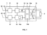
- Fig. 1 shows a schematic block diagram of an inventive Ballast for a discharge lamp in a lighting system.
- the numbered with 2 discharge lamp is denoted by the number 1 with e Ballast started and operated and has in particular preheatable Electrodes on.
- the electronic ballast (hereinafter the For brevity half ECG) has on the one hand a power connector 31 for connection a power supply line 32 and, on the other hand, a control terminal 41 for connecting a control line 42.
- the mains connection 31 leads via a radio-protection filter 11 and a rectifier with power factor correction (PFC) circuit to a smoothing capacitor 13, which includes an inverter 14, such as half-bridge topology, supplied with DC power.
- the inverter 14 essentially contains the functional blocks lamp circuit 14a and Heating circuit 14b and is connected via a transformer 15 with taps for the Heating the electrodes (as indicated graphically) connected to the lamp 2.
- control terminal 41 is connected to a digital electronic Interface 17 is connected and provides via this a control signal to a Microcontroller 16 with memory 16a.
- This microcontroller 16 is used for Control of the inverter, d. H. ultimately for controlling the lamp operation including preheating, ignition and dimming function.
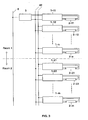
- FIG. 2 again shows a schematic of a method according to the invention Lighting system, wherein with 1-11 to 1-n and 1-21 to 1-m ECGs of the illustrated in Fig. 1 Type and with 2-11 to 2-n and 2-21 to 2-m connected to it Discharge lamps are designated according to the lamp 2 of FIG. 1.
- the drawn approximately in the middle of FIG. 2 dashed horizontal divides symbolically a first space above it from one below it second room. Some of the electronic ballasts and lamps are located in aiso the first and another part in the second room. In reality are Of course, further rooms and possibly also other electronic ballasts and lamps provided, so that you can think of Fig. 2 continued down.
- control unit 3a fulfills functions that are operated from both rooms while the controller 3b is accessible only in the first room.
- the control devices 3a and 3b are provided with control signal outputs on two bus signal lines 42 connected, whose branches of the drawn in Fig. 1 Control line 42 correspond.
- the control signal line 42 is thus bipolar and designed as a pure bus line, because at it both control devices 3a and 3b and all ECGs are connected.
- the respective network power supply 32 of the ECGs is not shown in Fig. 2 and done locally by principles not of interest to the invention. It is clear that over the controls and controls functions of each Lamps or electronic ballasts can be controlled purely by signal technology via a bus line 42 are, with the control signals in detail in more detail becomes.
- Fig. 3 shows an alternative to Fig. 2, wherein identical reference numerals corresponding Designate elements.
- a control unit 3 for the input of control commands is used in the control signal line 42, which in turn commands via a bus system in the form of the symbolic line 6 of a more general Building control system receives.
- the control unit 3 Here, the interface or the gateway between the links thereof by the building control system shown by the line 6 and the actual starting with the controller 3 lighting system.
- the Construction of the building control system and in particular the Command input are not shown here in detail; it's just about, too demonstrate that the inventive lighting system in such a system can be integrated.
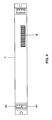
- FIG. 4 shows a concrete example of an electronic ballast 1 according to FIGS. 1-3 a cuboidal sheet metal housing is shown, in which the reference to FIG. 1 closer circuit explained is housed.
- the power connection 31 and the control terminal 41 right are four individual connections drawn for the lamp 2, but not quantified.
- the ECG 1 can over On the left and right outside recognizable recesses easily mounted in lights become.
- the electronic ballast 1 of FIG. 4 has an imprint 8 with a barcode and an alphanumeric representation of the corresponding code.
- the corresponding code is in the one shown in FIG. 1 shown semiconductor memory 16a of the microcontroller 16 in the ECG stored. It reflects the place, time and line of manufacture (at the factory) of the TOE again and may also contain information about the device type, about about the number of lamp outputs and operable lamp types.
- the installer can now in a correspondingly generated installation plan on paper and / or a corresponding file (read in by a barcode reader or typing in a notebook, for example) between the its installation predetermined position of the individual electronic ballast 1 in the lighting system according to Fig. 2 or Fig. 3 (ie whether it is there, for example, the electronic ballast 1-12 to the discharge lamp 2-12, for example, in the back right corner of the ceiling first room or around the ECG 1-21 to the discharge lamp 2-21, for example acting on the flur departmenten wall of the second room), and the Codes 8 make an assignment and this database is the programmer the control units 3 provide.
- the control unit / s communicated which ECG code 8 which Position corresponds.
- the corresponding ECG 1 is via the ECG code 8 then signal-technically accessible, d. H. responds to appropriate commands with the correct code input or gives the code on general request the control unit off.
- the control unit can therefore the respective ECGs 1 or codes 8 assign internal control addresses (in principle, the existing Use codes 8 as addresses).
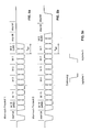
- FIGS. 5a and 5b schematically show the word structure (frame) of control commands between the control units 3 and ECGs 1 according to the two biphasecod striv Protocols.
- Fig. 5c the biphase coding is explained, the left falling edge rising from the high level to the low level Level of logical 1 and right complementary rising edge should correspond to the logical 0.
- the upper protocol 1 in this embodiment corresponds to the already mentioned DALI protocol and consists of a start bit (logical 1) and subsequently 16 information bits no. 15-0 and finally a stop bit which is a two bit length (plotted as T BIT ) persisting high level equivalent. MSB and LSB stand for the most significant or least significant bit.
- the second protocol which in this case is OSRAM-specific Communication protocol, drawn in the start bit the DALI protocol 1 is equivalent, but one word length extended by one bit and a level inverse stop bit. So the ECGs 1 can both based on the word length as well as the nature of the stop bit unique determine whether it is a DALI command or an OSRAM specific Command acts.
- Fig. 6 finally shows one of the different uses of the additional communication protocol, namely with a manufacturer-specific Readiness Command.
- Links are the meanings of horizontal running Plotted diagram lines, where a high level of the line an "on” and a low level “off” means. In the diagram shown starts from left to right current timeout thus with a switched off the standby mode.
- a helical preheat state for the time duration T P first follows with an on command, to which duration an ignition and thus a lamp operation (lowest horizontal line in the diagram jumps to "on”) follows.
- an inventive standby command takes place (top line jumps to "on"), which initially does not change the lamp operation itself. He has the consequence, however, that after a again indeterminate, but not over a certain maximum duration time, following Ausbetation leads on the one hand to an end of the lamp operation, but on the other hand at the same time to a restart of the filament heating. If after a certain time, again not over a certain maximum time, a new command follows, the lamp can unleash immediately in contrast to the first command (far left) without having to wait for a new preheat phase T P.
- the lighting system is thus able to turn on a standby state by the one provided by the second protocol Standby command an immediate restart of the lamp practically without time delay.
- Standby command an immediate restart of the lamp practically without time delay.
Landscapes
- Circuit Arrangement For Electric Light Sources In General (AREA)
- Selective Calling Equipment (AREA)
- Discharge-Lamp Control Circuits And Pulse- Feed Circuits (AREA)
- Cable Transmission Systems, Equalization Of Radio And Reduction Of Echo (AREA)
Applications Claiming Priority (2)
| Application Number | Priority Date | Filing Date | Title |
|---|---|---|---|
| DE10323689A DE10323689A1 (de) | 2003-05-22 | 2003-05-22 | Steuerbare Lichtanlage mit zweitem Kommunikationsprotokoll und Geräte hierfür |
| DE10323689 | 2003-05-22 |
Publications (3)
| Publication Number | Publication Date |
|---|---|
| EP1480496A2 true EP1480496A2 (fr) | 2004-11-24 |
| EP1480496A3 EP1480496A3 (fr) | 2008-09-10 |
| EP1480496B1 EP1480496B1 (fr) | 2011-03-02 |
Family
ID=33039309
Family Applications (1)
| Application Number | Title | Priority Date | Filing Date |
|---|---|---|---|
| EP04009349A Revoked EP1480496B1 (fr) | 2003-05-22 | 2004-04-20 | Installation d'éclairage commandable munie d'un second protocole de communication, et appareil à cet effet |
Country Status (6)
| Country | Link |
|---|---|
| US (1) | US7042173B2 (fr) |
| EP (1) | EP1480496B1 (fr) |
| JP (1) | JP4582620B2 (fr) |
| AT (1) | ATE500713T1 (fr) |
| CA (1) | CA2467560A1 (fr) |
| DE (2) | DE10323689A1 (fr) |
Cited By (5)
| Publication number | Priority date | Publication date | Assignee | Title |
|---|---|---|---|---|
| EP1069690A2 (fr) | 1999-07-15 | 2001-01-17 | Patent-Treuhand-Gesellschaft für elektrische Glühlampen mbH | Procédé d'échantillonage de signaux digitaux codés en biphase |
| WO2009114889A3 (fr) * | 2008-03-18 | 2011-03-10 | Tridonic Gmbh & Co Kg | Procédé de commande d'un appareil destiné à faire fonctionner des sources lumineuses, en particulier des del |
| EP2765835A1 (fr) * | 2006-06-22 | 2014-08-13 | Tridonic GmbH & Co KG | Appareil de fonctionnement à gradation doté d'une ligne de référence de gradation interne |
| AT16866U1 (de) * | 2015-09-18 | 2020-11-15 | Tridonic Gmbh & Co Kg | Gebäudetechnik-Bussystem mit Zentraleinheit, die dazu eingerichtet ist, Befehle mit unterschiedlichen Frame-Zeitdauern zu übermitteln |
| EP2276327B1 (fr) * | 2004-12-20 | 2021-02-03 | Tridonic GmbH & Co KG | Procédé pour programmer un équipement d'élément d'éclairage |
Families Citing this family (25)
| Publication number | Priority date | Publication date | Assignee | Title |
|---|---|---|---|---|
| AU2003252113A1 (en) * | 2002-07-26 | 2004-02-16 | Humdinger, Inc. | Stripper-plate alignment system and die set |
| DE10323752A1 (de) * | 2003-05-22 | 2004-12-09 | Patent-Treuhand-Gesellschaft für elektrische Glühlampen mbH | Verfahren zum Betreiben einer Lichtanlage |
| DE10323690A1 (de) * | 2003-05-22 | 2004-12-09 | Patent-Treuhand-Gesellschaft für elektrische Glühlampen mbH | Lichtanlage und Verfahren zur Herstellung derselben |
| DE10329876B4 (de) * | 2003-07-02 | 2016-06-02 | Tridonic Gmbh & Co Kg | Schnittstelle für ein Lampenbetriebsgerät mit niedrigen Standby-Verlusten und Verfahren zur Ansteuerung eines Lampenbetriebsgeräts über eine derartige Schnittstelle |
| US20070194721A1 (en) * | 2004-08-20 | 2007-08-23 | Vatche Vorperian | Electronic lighting ballast with multiple outputs to drive electric discharge lamps of different wattage |
| US7369060B2 (en) * | 2004-12-14 | 2008-05-06 | Lutron Electronics Co., Inc. | Distributed intelligence ballast system and extended lighting control protocol |
| US20060273738A1 (en) * | 2005-06-06 | 2006-12-07 | Holst Barrie J | Cold cathode fluorescent lamp |
| CA2708978C (fr) * | 2006-12-11 | 2016-03-15 | Tir Technology Lp | Systeme et procede de commande de luminaire |
| CN101569239A (zh) * | 2006-12-11 | 2009-10-28 | Tir科技公司 | 数字控制照明设备的方法和装置 |
| US20080136334A1 (en) * | 2006-12-12 | 2008-06-12 | Robinson Shane P | System and method for controlling lighting |
| US8220957B2 (en) * | 2007-02-12 | 2012-07-17 | Abl Ip Holding Llc | Retrofit light assembly |
| EP2020778A1 (fr) * | 2007-08-02 | 2009-02-04 | Daniel Dipl.-Ing. Burkhalter | Composant pour l'utilisation dans un réseau électrique et/ou électronique, réseau, procédé de configuration d'un réseau ainsi que produit de programme informatique |
| DE102007040111B3 (de) * | 2007-08-24 | 2008-10-23 | Siemens Ag | Verfahren zur Inbetriebsetzung eines Beleuchtungssystems |
| US20090244908A1 (en) * | 2008-04-01 | 2009-10-01 | Stephen Haight Lydecker | Louver for Light Assembly |
| USD640825S1 (en) | 2008-04-24 | 2011-06-28 | Abl Ip Holding Llc | Louver |
| USD612534S1 (en) | 2008-04-24 | 2010-03-23 | Abl Ip Holding Llc | Bracket |
| JP2010009792A (ja) * | 2008-06-24 | 2010-01-14 | Panasonic Electric Works Co Ltd | 照明システムおよび照明器具 |
| US8405488B1 (en) | 2008-10-21 | 2013-03-26 | Universal Lighting Technologies, Inc. | System and method for encoding ballast control signals |
| US8072164B2 (en) * | 2008-10-28 | 2011-12-06 | General Electric Company | Unified 0-10V and DALI dimming interface circuit |
| US8680969B2 (en) * | 2009-03-20 | 2014-03-25 | Lutron Electronics Co., Inc. | Method of confirming that a control device complies with a predefined protocol standard |
| US8540522B2 (en) | 2010-10-05 | 2013-09-24 | Lumetric Lighting, Inc. | Utility control system and method |
| EP2891384B1 (fr) * | 2012-08-29 | 2020-08-05 | Light And Save | Dispositif électronique de contrôle et d'alimentation de lampes à décharge |
| US9125252B1 (en) * | 2013-03-04 | 2015-09-01 | Universal Lighting Technologies, Inc. | Power line communication system and method for control of lamp dimming |
| GB2550248B (en) * | 2016-03-10 | 2020-04-22 | Gooee Ltd | Universal smart lighting gateway |
| DE102022110533A1 (de) | 2022-04-29 | 2023-11-02 | Tridonic Gmbh & Co Kg | Vorrichtung und Verfahren zum Übertragen eines Parameters an ein Betriebsgerät der Beleuchtungstechnik und Markieren desselben |
Citations (2)
| Publication number | Priority date | Publication date | Assignee | Title |
|---|---|---|---|---|
| US5842039A (en) | 1996-05-28 | 1998-11-24 | Allen Bradley Company, Llc | Most recent first dynamic protocol detection for use with a programmable controller |
| US20020154025A1 (en) | 2001-04-24 | 2002-10-24 | Koniklijke Philips Electronics N.V. | Wireless addressable lighting method and apparatus |
Family Cites Families (11)
| Publication number | Priority date | Publication date | Assignee | Title |
|---|---|---|---|---|
| DE19932692A1 (de) * | 1999-07-15 | 2001-01-18 | Patent Treuhand Ges Fuer Elektrische Gluehlampen Mbh | Verfahren zur Abtastung biphase codierter digitaler Signale |
| US6990082B1 (en) * | 1999-11-08 | 2006-01-24 | Intel Corporation | Wireless apparatus having a transceiver equipped to support multiple wireless communication protocols |
| US6333605B1 (en) * | 1999-11-02 | 2001-12-25 | Energy Savings, Inc. | Light modulating electronic ballast |
| US6507158B1 (en) * | 2000-11-15 | 2003-01-14 | Koninkljke Philips Electronics N.V. | Protocol enhancement for lighting control networks and communications interface for same |
| US6865347B2 (en) * | 2001-01-05 | 2005-03-08 | Motorola, Inc. | Optically-based location system and method for determining a location at a structure |
| US6771029B2 (en) * | 2001-03-28 | 2004-08-03 | International Rectifier Corporation | Digital dimming fluorescent ballast |
| US6762570B1 (en) * | 2001-04-10 | 2004-07-13 | Microchip Technology Incorporated | Minimizing standby power in a digital addressable lighting interface |
| US20030036807A1 (en) * | 2001-08-14 | 2003-02-20 | Fosler Ross M. | Multiple master digital addressable lighting interface (DALI) system, method and apparatus |
| US20040217718A1 (en) * | 2003-05-02 | 2004-11-04 | Russikesh Kumar | Digital addressable electronic ballast and control unit |
| US6867558B2 (en) * | 2003-05-12 | 2005-03-15 | General Electric Company | Method and apparatus for networked lighting system control |
| US7170238B2 (en) * | 2003-07-30 | 2007-01-30 | Colorado Vnet, Llc | Control systems and methods |
-
2003
- 2003-05-22 DE DE10323689A patent/DE10323689A1/de not_active Withdrawn
-
2004
- 2004-04-20 AT AT04009349T patent/ATE500713T1/de active
- 2004-04-20 EP EP04009349A patent/EP1480496B1/fr not_active Revoked
- 2004-04-20 DE DE502004012244T patent/DE502004012244D1/de not_active Expired - Lifetime
- 2004-05-12 US US10/843,334 patent/US7042173B2/en not_active Expired - Lifetime
- 2004-05-19 CA CA002467560A patent/CA2467560A1/fr not_active Abandoned
- 2004-05-20 JP JP2004150834A patent/JP4582620B2/ja not_active Expired - Fee Related
Patent Citations (2)
| Publication number | Priority date | Publication date | Assignee | Title |
|---|---|---|---|---|
| US5842039A (en) | 1996-05-28 | 1998-11-24 | Allen Bradley Company, Llc | Most recent first dynamic protocol detection for use with a programmable controller |
| US20020154025A1 (en) | 2001-04-24 | 2002-10-24 | Koniklijke Philips Electronics N.V. | Wireless addressable lighting method and apparatus |
Cited By (6)
| Publication number | Priority date | Publication date | Assignee | Title |
|---|---|---|---|---|
| EP1069690A2 (fr) | 1999-07-15 | 2001-01-17 | Patent-Treuhand-Gesellschaft für elektrische Glühlampen mbH | Procédé d'échantillonage de signaux digitaux codés en biphase |
| EP2276327B1 (fr) * | 2004-12-20 | 2021-02-03 | Tridonic GmbH & Co KG | Procédé pour programmer un équipement d'élément d'éclairage |
| EP2765835A1 (fr) * | 2006-06-22 | 2014-08-13 | Tridonic GmbH & Co KG | Appareil de fonctionnement à gradation doté d'une ligne de référence de gradation interne |
| WO2009114889A3 (fr) * | 2008-03-18 | 2011-03-10 | Tridonic Gmbh & Co Kg | Procédé de commande d'un appareil destiné à faire fonctionner des sources lumineuses, en particulier des del |
| CN102150477A (zh) * | 2008-03-18 | 2011-08-10 | 赤多尼科两合股份有限公司 | 用于发光器件尤其是led的操作装置的控制方法 |
| AT16866U1 (de) * | 2015-09-18 | 2020-11-15 | Tridonic Gmbh & Co Kg | Gebäudetechnik-Bussystem mit Zentraleinheit, die dazu eingerichtet ist, Befehle mit unterschiedlichen Frame-Zeitdauern zu übermitteln |
Also Published As
| Publication number | Publication date |
|---|---|
| CA2467560A1 (fr) | 2004-11-22 |
| JP4582620B2 (ja) | 2010-11-17 |
| EP1480496B1 (fr) | 2011-03-02 |
| EP1480496A3 (fr) | 2008-09-10 |
| JP2004349256A (ja) | 2004-12-09 |
| ATE500713T1 (de) | 2011-03-15 |
| US7042173B2 (en) | 2006-05-09 |
| DE10323689A1 (de) | 2004-12-09 |
| DE502004012244D1 (de) | 2011-04-14 |
| US20040245943A1 (en) | 2004-12-09 |
Similar Documents
| Publication | Publication Date | Title |
|---|---|---|
| EP1480495B1 (fr) | Installation d'éclairage et méthode pour sa mise en service | |
| EP1480496B1 (fr) | Installation d'éclairage commandable munie d'un second protocole de communication, et appareil à cet effet | |
| EP1519634B1 (fr) | Convertisseur de données pour une installation d'éclairage et procédé de fonctionnement d'une installation d'éclairage | |
| EP0639938B1 (fr) | Dispositif de commande d'éclairage par zones | |
| EP2288238B1 (fr) | Commande des dispositifs d'éclairage par des signaux modulés sur bus à courant continu | |
| EP1480498A2 (fr) | Procédé pour commander une installation d'éclairage | |
| DE102004039677B4 (de) | Gebäudemanagementsystem und Aktor mit Speicherteil | |
| EP1829429A1 (fr) | Procede pour programmer un equipement d'element d'eclairage | |
| EP1292175B1 (fr) | Management d'un système lumineux avec starter électronique | |
| WO2005032218A1 (fr) | Systeme de commande pour plusieurs dispositifs de commande d'ampoule repartis, et procede d'initialisation d'un tel systeme de commande | |
| EP1035755B1 (fr) | Méthode de mise en service des moyens de commande d'un système d'éclairage | |
| EP2359579B1 (fr) | Procédé d'adressage pour un moyen d'éclairage, en particulier des diodes électroluminescentes | |
| EP1955578B1 (fr) | Systeme de commande concu pour plusieurs recepteurs separes, en particulier des dispositifs fonctionnant avec des lampes, et procede de mise en marche de celui-ci | |
| EP1555861B1 (fr) | Commande d' appareils d' éclairage par modulation sur un bus à courant continu | |
| EP1624729B1 (fr) | Procédé pour la installation d'un système de illumination | |
| WO2013023230A2 (fr) | Procédé d'addressage d'appareils d'actionnement d'éléments luminescents | |
| EP2365737B1 (fr) | PFC central doté d'une régulation de sortie CC | |
| DE10312183A1 (de) | Gebäudeinstallationssystem | |
| WO2011041817A2 (fr) | Procédé d'excitation d'appareils de commande de luminaires | |
| DE202005006465U1 (de) | Lampenbetriebsgerät mit Empfangseinrichtung für externe Steuerbefehle | |
| DE102012218571A1 (de) | Verfahren und vorrichtung zum zuordnen von netzidentifikationen in einem beleuchtungssystem und beleuchtungssystem | |
| AT507128B1 (de) | Verfahren zur ansteuerung für ein betriebsgerät für leuchtmittel | |
| EP2892305A1 (fr) | Variateur | |
| DE102019105344A1 (de) | Verfahren zur Nutzung eines Beleuchtungssystems | |
| DE102008035219A1 (de) | Steuerschaltung zur Steuerung einer Lampenbetriebsschaltung für Leuchtmittel |
Legal Events
| Date | Code | Title | Description |
|---|---|---|---|
| PUAI | Public reference made under article 153(3) epc to a published international application that has entered the european phase |
Free format text: ORIGINAL CODE: 0009012 |
|
| AK | Designated contracting states |
Kind code of ref document: A2 Designated state(s): AT BE BG CH CY CZ DE DK EE ES FI FR GB GR HU IE IT LI LU MC NL PL PT RO SE SI SK TR |
|
| AX | Request for extension of the european patent |
Extension state: AL HR LT LV MK |
|
| PUAL | Search report despatched |
Free format text: ORIGINAL CODE: 0009013 |
|
| AK | Designated contracting states |
Kind code of ref document: A3 Designated state(s): AT BE BG CH CY CZ DE DK EE ES FI FR GB GR HU IE IT LI LU MC NL PL PT RO SE SI SK TR |
|
| AX | Request for extension of the european patent |
Extension state: AL HR LT LV MK |
|
| 17P | Request for examination filed |
Effective date: 20090223 |
|
| 17Q | First examination report despatched |
Effective date: 20090330 |
|
| AKX | Designation fees paid |
Designated state(s): AT BE BG CH CY CZ DE DK EE ES FI FR GB GR HU IE IT LI LU MC NL PL PT RO SE SI SK TR |
|
| R17C | First examination report despatched (corrected) |
Effective date: 20090330 |
|
| GRAP | Despatch of communication of intention to grant a patent |
Free format text: ORIGINAL CODE: EPIDOSNIGR1 |
|
| RAP1 | Party data changed (applicant data changed or rights of an application transferred) |
Owner name: OSRAM GESELLSCHAFT MIT BESCHRAENKTER HAFTUNG |
|
| GRAS | Grant fee paid |
Free format text: ORIGINAL CODE: EPIDOSNIGR3 |
|
| GRAA | (expected) grant |
Free format text: ORIGINAL CODE: 0009210 |
|
| AK | Designated contracting states |
Kind code of ref document: B1 Designated state(s): AT BE BG CH CY CZ DE DK EE ES FI FR GB GR HU IE IT LI LU MC NL PL PT RO SE SI SK TR |
|
| REG | Reference to a national code |
Ref country code: GB Ref legal event code: FG4D Free format text: NOT ENGLISH |
|
| REG | Reference to a national code |
Ref country code: CH Ref legal event code: EP Ref country code: CH Ref legal event code: NV Representative=s name: SIEMENS SCHWEIZ AG |
|
| REG | Reference to a national code |
Ref country code: IE Ref legal event code: FG4D Free format text: LANGUAGE OF EP DOCUMENT: GERMAN |
|
| REF | Corresponds to: |
Ref document number: 502004012244 Country of ref document: DE Date of ref document: 20110414 Kind code of ref document: P |
|
| REG | Reference to a national code |
Ref country code: DE Ref legal event code: R096 Ref document number: 502004012244 Country of ref document: DE Effective date: 20110414 |
|
| REG | Reference to a national code |
Ref country code: SE Ref legal event code: TRGR |
|
| REG | Reference to a national code |
Ref country code: NL Ref legal event code: VDEP Effective date: 20110302 |
|
| PG25 | Lapsed in a contracting state [announced via postgrant information from national office to epo] |
Ref country code: ES Free format text: LAPSE BECAUSE OF FAILURE TO SUBMIT A TRANSLATION OF THE DESCRIPTION OR TO PAY THE FEE WITHIN THE PRESCRIBED TIME-LIMIT Effective date: 20110613 Ref country code: GR Free format text: LAPSE BECAUSE OF FAILURE TO SUBMIT A TRANSLATION OF THE DESCRIPTION OR TO PAY THE FEE WITHIN THE PRESCRIBED TIME-LIMIT Effective date: 20110603 |
|
| PG25 | Lapsed in a contracting state [announced via postgrant information from national office to epo] |
Ref country code: BG Free format text: LAPSE BECAUSE OF FAILURE TO SUBMIT A TRANSLATION OF THE DESCRIPTION OR TO PAY THE FEE WITHIN THE PRESCRIBED TIME-LIMIT Effective date: 20110602 Ref country code: SI Free format text: LAPSE BECAUSE OF FAILURE TO SUBMIT A TRANSLATION OF THE DESCRIPTION OR TO PAY THE FEE WITHIN THE PRESCRIBED TIME-LIMIT Effective date: 20110302 Ref country code: CY Free format text: LAPSE BECAUSE OF FAILURE TO SUBMIT A TRANSLATION OF THE DESCRIPTION OR TO PAY THE FEE WITHIN THE PRESCRIBED TIME-LIMIT Effective date: 20110302 Ref country code: NL Free format text: LAPSE BECAUSE OF FAILURE TO SUBMIT A TRANSLATION OF THE DESCRIPTION OR TO PAY THE FEE WITHIN THE PRESCRIBED TIME-LIMIT Effective date: 20110302 |
|
| REG | Reference to a national code |
Ref country code: IE Ref legal event code: FD4D |
|
| BERE | Be: lapsed |
Owner name: OSRAM G.M.B.H. Effective date: 20110430 |
|
| PG25 | Lapsed in a contracting state [announced via postgrant information from national office to epo] |
Ref country code: PT Free format text: LAPSE BECAUSE OF FAILURE TO SUBMIT A TRANSLATION OF THE DESCRIPTION OR TO PAY THE FEE WITHIN THE PRESCRIBED TIME-LIMIT Effective date: 20110704 Ref country code: IE Free format text: LAPSE BECAUSE OF FAILURE TO SUBMIT A TRANSLATION OF THE DESCRIPTION OR TO PAY THE FEE WITHIN THE PRESCRIBED TIME-LIMIT Effective date: 20110302 Ref country code: EE Free format text: LAPSE BECAUSE OF FAILURE TO SUBMIT A TRANSLATION OF THE DESCRIPTION OR TO PAY THE FEE WITHIN THE PRESCRIBED TIME-LIMIT Effective date: 20110302 |
|
| PG25 | Lapsed in a contracting state [announced via postgrant information from national office to epo] |
Ref country code: CZ Free format text: LAPSE BECAUSE OF FAILURE TO SUBMIT A TRANSLATION OF THE DESCRIPTION OR TO PAY THE FEE WITHIN THE PRESCRIBED TIME-LIMIT Effective date: 20110302 Ref country code: SK Free format text: LAPSE BECAUSE OF FAILURE TO SUBMIT A TRANSLATION OF THE DESCRIPTION OR TO PAY THE FEE WITHIN THE PRESCRIBED TIME-LIMIT Effective date: 20110302 Ref country code: MC Free format text: LAPSE BECAUSE OF NON-PAYMENT OF DUE FEES Effective date: 20110430 Ref country code: RO Free format text: LAPSE BECAUSE OF FAILURE TO SUBMIT A TRANSLATION OF THE DESCRIPTION OR TO PAY THE FEE WITHIN THE PRESCRIBED TIME-LIMIT Effective date: 20110302 |
|
| PLBI | Opposition filed |
Free format text: ORIGINAL CODE: 0009260 |
|
| PLAX | Notice of opposition and request to file observation + time limit sent |
Free format text: ORIGINAL CODE: EPIDOSNOBS2 |
|
| 26 | Opposition filed |
Opponent name: HELVAR OY AB Effective date: 20111202 |
|
| PG25 | Lapsed in a contracting state [announced via postgrant information from national office to epo] |
Ref country code: BE Free format text: LAPSE BECAUSE OF NON-PAYMENT OF DUE FEES Effective date: 20110430 |
|
| REG | Reference to a national code |
Ref country code: DE Ref legal event code: R081 Ref document number: 502004012244 Country of ref document: DE Owner name: OSRAM GMBH, DE Free format text: FORMER OWNER: OSRAM GESELLSCHAFT MIT BESCHRAENKTER HAFTUNG, 81543 MUENCHEN, DE Effective date: 20111213 Ref country code: DE Ref legal event code: R081 Ref document number: 502004012244 Country of ref document: DE Owner name: OSRAM GMBH, DE Free format text: FORMER OWNER: PATENT-TREUHAND-GESELLSCHAFT FUER ELEKTRISCHE GLUEHLAMPEN MBH, 81543 MUENCHEN, DE Effective date: 20110203 |
|
| PG25 | Lapsed in a contracting state [announced via postgrant information from national office to epo] |
Ref country code: PL Free format text: LAPSE BECAUSE OF FAILURE TO SUBMIT A TRANSLATION OF THE DESCRIPTION OR TO PAY THE FEE WITHIN THE PRESCRIBED TIME-LIMIT Effective date: 20110302 |
|
| REG | Reference to a national code |
Ref country code: DE Ref legal event code: R026 Ref document number: 502004012244 Country of ref document: DE Effective date: 20111202 |
|
| PLAF | Information modified related to communication of a notice of opposition and request to file observations + time limit |
Free format text: ORIGINAL CODE: EPIDOSCOBS2 |
|
| PLBB | Reply of patent proprietor to notice(s) of opposition received |
Free format text: ORIGINAL CODE: EPIDOSNOBS3 |
|
| PGFP | Annual fee paid to national office [announced via postgrant information from national office to epo] |
Ref country code: SE Payment date: 20120410 Year of fee payment: 9 |
|
| REG | Reference to a national code |
Ref country code: DE Ref legal event code: R081 Ref document number: 502004012244 Country of ref document: DE Owner name: OSRAM GMBH, DE Free format text: FORMER OWNER: OSRAM AG, 81543 MUENCHEN, DE Effective date: 20130205 |
|
| PGFP | Annual fee paid to national office [announced via postgrant information from national office to epo] |
Ref country code: AT Payment date: 20120309 Year of fee payment: 9 |
|
| RAP2 | Party data changed (patent owner data changed or rights of a patent transferred) |
Owner name: OSRAM GMBH |
|
| PG25 | Lapsed in a contracting state [announced via postgrant information from national office to epo] |
Ref country code: LU Free format text: LAPSE BECAUSE OF NON-PAYMENT OF DUE FEES Effective date: 20110420 |
|
| PG25 | Lapsed in a contracting state [announced via postgrant information from national office to epo] |
Ref country code: TR Free format text: LAPSE BECAUSE OF FAILURE TO SUBMIT A TRANSLATION OF THE DESCRIPTION OR TO PAY THE FEE WITHIN THE PRESCRIBED TIME-LIMIT Effective date: 20110302 |
|
| REG | Reference to a national code |
Ref country code: DE Ref legal event code: R081 Ref document number: 502004012244 Country of ref document: DE Owner name: OSRAM GMBH, DE Free format text: FORMER OWNER: OSRAM GMBH, 81543 MUENCHEN, DE Effective date: 20130822 |
|
| PG25 | Lapsed in a contracting state [announced via postgrant information from national office to epo] |
Ref country code: HU Free format text: LAPSE BECAUSE OF FAILURE TO SUBMIT A TRANSLATION OF THE DESCRIPTION OR TO PAY THE FEE WITHIN THE PRESCRIBED TIME-LIMIT Effective date: 20110302 |
|
| RDAF | Communication despatched that patent is revoked |
Free format text: ORIGINAL CODE: EPIDOSNREV1 |
|
| REG | Reference to a national code |
Ref country code: SE Ref legal event code: EUG |
|
| REG | Reference to a national code |
Ref country code: AT Ref legal event code: MM01 Ref document number: 500713 Country of ref document: AT Kind code of ref document: T Effective date: 20130430 |
|
| APBM | Appeal reference recorded |
Free format text: ORIGINAL CODE: EPIDOSNREFNO |
|
| APBP | Date of receipt of notice of appeal recorded |
Free format text: ORIGINAL CODE: EPIDOSNNOA2O |
|
| APAH | Appeal reference modified |
Free format text: ORIGINAL CODE: EPIDOSCREFNO |
|
| PG25 | Lapsed in a contracting state [announced via postgrant information from national office to epo] |
Ref country code: SE Free format text: LAPSE BECAUSE OF NON-PAYMENT OF DUE FEES Effective date: 20130421 Ref country code: AT Free format text: LAPSE BECAUSE OF NON-PAYMENT OF DUE FEES Effective date: 20130430 |
|
| APAL | Date of receipt of statement of grounds of an appeal modified |
Free format text: ORIGINAL CODE: EPIDOSCNOA3O |
|
| APBQ | Date of receipt of statement of grounds of appeal recorded |
Free format text: ORIGINAL CODE: EPIDOSNNOA3O |
|
| PLAB | Opposition data, opponent's data or that of the opponent's representative modified |
Free format text: ORIGINAL CODE: 0009299OPPO |
|
| R26 | Opposition filed (corrected) |
Opponent name: HELVAR OY AB Effective date: 20111202 |
|
| REG | Reference to a national code |
Ref country code: FR Ref legal event code: PLFP Year of fee payment: 13 |
|
| REG | Reference to a national code |
Ref country code: FR Ref legal event code: PLFP Year of fee payment: 14 |
|
| REG | Reference to a national code |
Ref country code: FR Ref legal event code: PLFP Year of fee payment: 15 |
|
| PGFP | Annual fee paid to national office [announced via postgrant information from national office to epo] |
Ref country code: CH Payment date: 20180419 Year of fee payment: 15 |
|
| PGFP | Annual fee paid to national office [announced via postgrant information from national office to epo] |
Ref country code: IT Payment date: 20180423 Year of fee payment: 15 |
|
| PLAB | Opposition data, opponent's data or that of the opponent's representative modified |
Free format text: ORIGINAL CODE: 0009299OPPO |
|
| R26 | Opposition filed (corrected) |
Opponent name: HELVAR OY AB Effective date: 20111202 |
|
| REG | Reference to a national code |
Ref country code: DE Ref legal event code: R064 Ref document number: 502004012244 Country of ref document: DE Ref country code: DE Ref legal event code: R103 Ref document number: 502004012244 Country of ref document: DE |
|
| APBU | Appeal procedure closed |
Free format text: ORIGINAL CODE: EPIDOSNNOA9O |
|
| PGFP | Annual fee paid to national office [announced via postgrant information from national office to epo] |
Ref country code: DE Payment date: 20190418 Year of fee payment: 16 Ref country code: FI Payment date: 20190424 Year of fee payment: 16 |
|
| RDAG | Patent revoked |
Free format text: ORIGINAL CODE: 0009271 |
|
| STAA | Information on the status of an ep patent application or granted ep patent |
Free format text: STATUS: PATENT REVOKED |
|
| REG | Reference to a national code |
Ref country code: CH Ref legal event code: PL |
|
| PGFP | Annual fee paid to national office [announced via postgrant information from national office to epo] |
Ref country code: FR Payment date: 20190418 Year of fee payment: 16 |
|
| 27W | Patent revoked |
Effective date: 20190508 |
|
| GBPR | Gb: patent revoked under art. 102 of the ep convention designating the uk as contracting state |
Effective date: 20190508 |
|
| PGFP | Annual fee paid to national office [announced via postgrant information from national office to epo] |
Ref country code: GB Payment date: 20190418 Year of fee payment: 16 |
|
| REG | Reference to a national code |
Ref country code: AT Ref legal event code: MA03 Ref document number: 500713 Country of ref document: AT Kind code of ref document: T Effective date: 20190508 |